Page 3319 of 4770
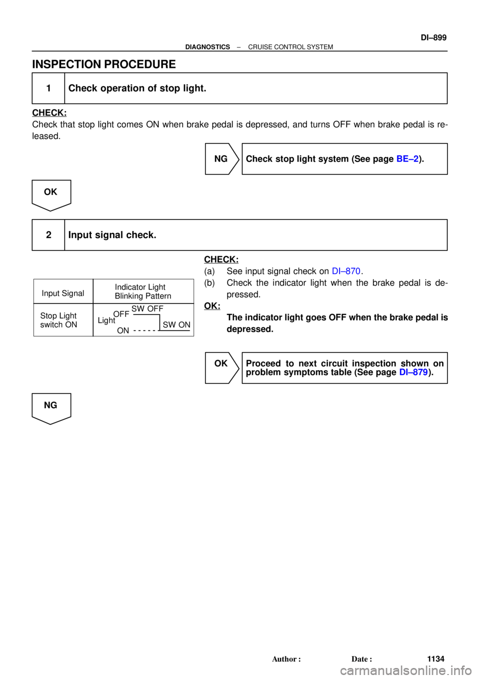
Input SignalIndicator Light
Blinking Pattern
Stop Light
switch ON
LightOFF
ONSW OFF
SW ON
± DIAGNOSTICSCRUISE CONTROL SYSTEM
DI±899
1134 Author�: Date�:
INSPECTION PROCEDURE
1 Check operation of stop light.
CHECK:
Check that stop light comes ON when brake pedal is depressed, and turns OFF when brake pedal is re-
leased.
NG Check stop light system (See page BE±2).
OK
2 Input signal check.
CHECK:
(a) See input signal check on DI±870.
(b) Check the indicator light when the brake pedal is de-
pressed.
OK:
The indicator light goes OFF when the brake pedal is
depressed.
OK Proceed to next circuit inspection shown on
problem symptoms table (See page DI±879).
NG
Page 3320 of 4770
AB0119
I00142
I00173
ON
STP±
(±) (+)
DI±900
± DIAGNOSTICSCRUISE CONTROL SYSTEM
1135 Author�: Date�:
3 Check voltage between terminal STP± of cruise control ECU connector and
body ground.
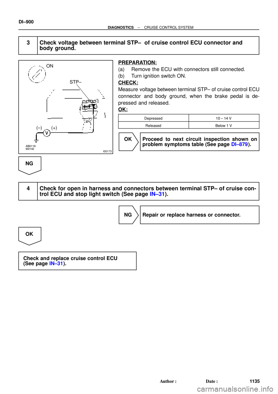
PREPARATION:
(a) Remove the ECU with connectors still connected.
(b) Turn ignition switch ON.
CHECK:
Measure voltage between terminal STP± of cruise control ECU
connector and body ground, when the brake pedal is de-
pressed and released.
OK:
Depressed10 ± 14 V
ReleasedBelow 1 V
OK Proceed to next circuit inspection shown on
problem symptoms table (See page DI±879).
NG
4 Check for open in harness and connectors between terminal STP± of cruise con-
trol ECU and stop light switch (See page IN±31).
NG Repair or replace harness or connector.
OK
Check and replace cruise control ECU
(See page IN±31).
Page 3643 of 4770

Z08523
1
2
341 2
43
I21683
12
34
1
2 4
3
55
± BODY ELECTRICALHEADLIGHT AND TAILLIGHT SYSTEM
BE±25
2235 Author�: Date�:
2001 CAMRY (RM819U)Tester connection
ConditionSpecified condition
1 ± GroundConstantBattery positive voltage
2 ± GroundConstantBattery positive voltage
3 ± GroundConstantBattery positive voltage
4 ± GroundLight control switch position OFF or HEADNo voltage
4 ± GroundLight control switch position TAILContinuity
5 ± GroundConstantBattery positive voltage
7 ± GroundLight control switch position OFF or TAILNo continuity
7 ± GroundLight control switch position HEADContinuity
8 ± GroundHeadlight dimmer switch position
Low beamNo continuity
8 ± GroundHeadlight dimmer switch position
High beam of FlashContinuity
9 ± GroundEngine StopNo voltage
9 ± GroundEngine RunningBattery positive voltage
10 ± GroundIgnition switch position LOCK or ACCNo voltage
10 ± GroundIgnition switch position ON or STARTBattery positive voltage
14 ± GroundConstantContinuity
17 ± GroundBrake fluid level warning position OFFNo continuity
17 ± GroundBrake fluid level warning position ONContinuity
18 ± GroundParking brake switch position OFF
(Parking brake lever released)No continuity
18 ± GroundParking brake switch position ON
(Parking brake lever pulled up)Continuity
If circuit is as specified, try replacing the relay with a new one.
If circuit is not as specified, inspect the circuits connected to oth-
er parts.
6. w/ Daytime running light system:
INSPECT DAYTIME RUNNING LIGHT NO.2 RELAY
CONTINUITY
ConditionTester connectionSpecified condition
Constant1 ± 4, 2 ± 4Continuity
Apply B+ between
terminals 2 and 4.3 ± 4Continuity
If continuity is not as specified, replace the relay.
7. w/ Daytime running light system:
INSPECT DAYTIME RUNNING LIGHT NO.3 RELAY-
CONTINUITY
ConditionTester connectionSpecified condition
Constant1 ± 2, 3 ± 4Continuity
Apply B+ between
terminals 1 and 2.3 ± 5Continuity
If continuity is not as specified, replace the relay.
Page 3644 of 4770

Z08559
1
2
341 2
43
I08422
I08423
BE±26
± BODY ELECTRICALHEADLIGHT AND TAILLIGHT SYSTEM
2236 Author�: Date�:
2001 CAMRY (RM819U)
8. w/ Daytime running light system:
INSPECT DAYTIME RUNNING LIGHT NO.4 RELAY
CONTINUITY
ConditionTester connectionSpecified condition
Constant3 ± 4Continuity
Apply B+ between
terminals 3 and 4.1 ± 2Continuity
If continuity is not as specified, replace the relay.
9. INSPECT LIGHT AUTO TURN OFF SYSTEM
(See Integration relay circuit on page BE±14)
10. w/ Automatic Light Control System:
INSPECT AUTOMATIC LIGHT CONTROL
(a) Turn the ignition switch ON.
(b) Turn the light control switch to OFF.
(c) Parking brake lever released.
(d) Gradually cover the top of the sensor.
(e) Verify that the lights should turn ON the accessory lights
and the headlights.
11. w/ Automatic Light Control System:
INSPECT AUTOMATIC LIGHT CONTROL
(a) Gradually expose the sensor.
(b) Verify that the lights should turn OFF the headlights and
the accessory lights.
12. w/ Automatic Light Control System:
INSPECT LIGHT±OFF CONDITION
(a) Turn the ignition switch ON.
(b) Gradually cover the top of the sensor.
Lights auto ON:
13. w/ Automatic Light Control System:
INSPECT LIGHTS±ON CONDITION
(a) Open the driver's door while the ignition switch is OFF.
(b) Turn the light control switch to OFF leaving the door open
and cover the top of the sensor, and verify that the lights
go on when the ignition switch is turned ON.
Page 3756 of 4770
MA0055
MA00M±01
MA±6
± MAINTENANCEBRAKE
49 Author�: Date�:
BRAKE
INSPECTION
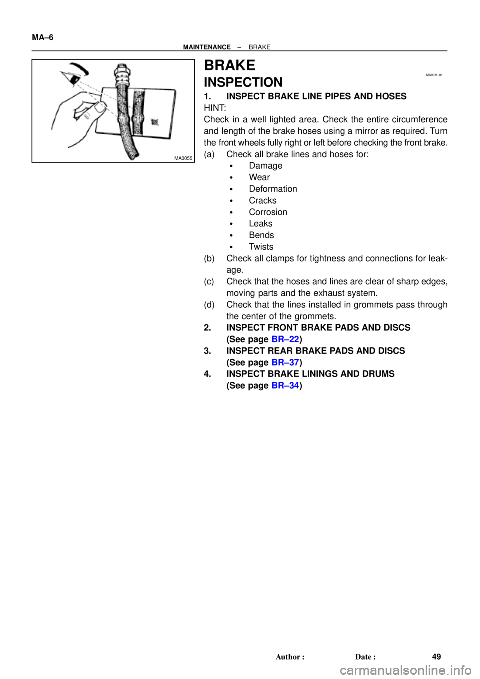
1. INSPECT BRAKE LINE PIPES AND HOSES
HINT:
Check in a well lighted area. Check the entire circumference
and length of the brake hoses using a mirror as required. Turn
the front wheels fully right or left before checking the front brake.
(a) Check all brake lines and hoses for:
�Damage
�Wear
�Deformation
�Cracks
�Corrosion
�Leaks
�Bends
�Twists
(b) Check all clamps for tightness and connections for leak-
age.
(c) Check that the hoses and lines are clear of sharp edges,
moving parts and the exhaust system.
(d) Check that the lines installed in grommets pass through
the center of the grommets.
2. INSPECT FRONT BRAKE PADS AND DISCS
(See page BR±22)
3. INSPECT REAR BRAKE PADS AND DISCS
(See page BR±37)
4. INSPECT BRAKE LININGS AND DRUMS
(See page BR±34)
Page 4037 of 4770
S05523
New Gasket
FI1654
SST
30 cm Fulcrum Length
FI0420
Injector
GrommetO±Ring
Delivery PipeCORRECT
WRONG
± SFI (5S±FE)SFI SYSTEM
SF±3
1436 Author�: Date�:
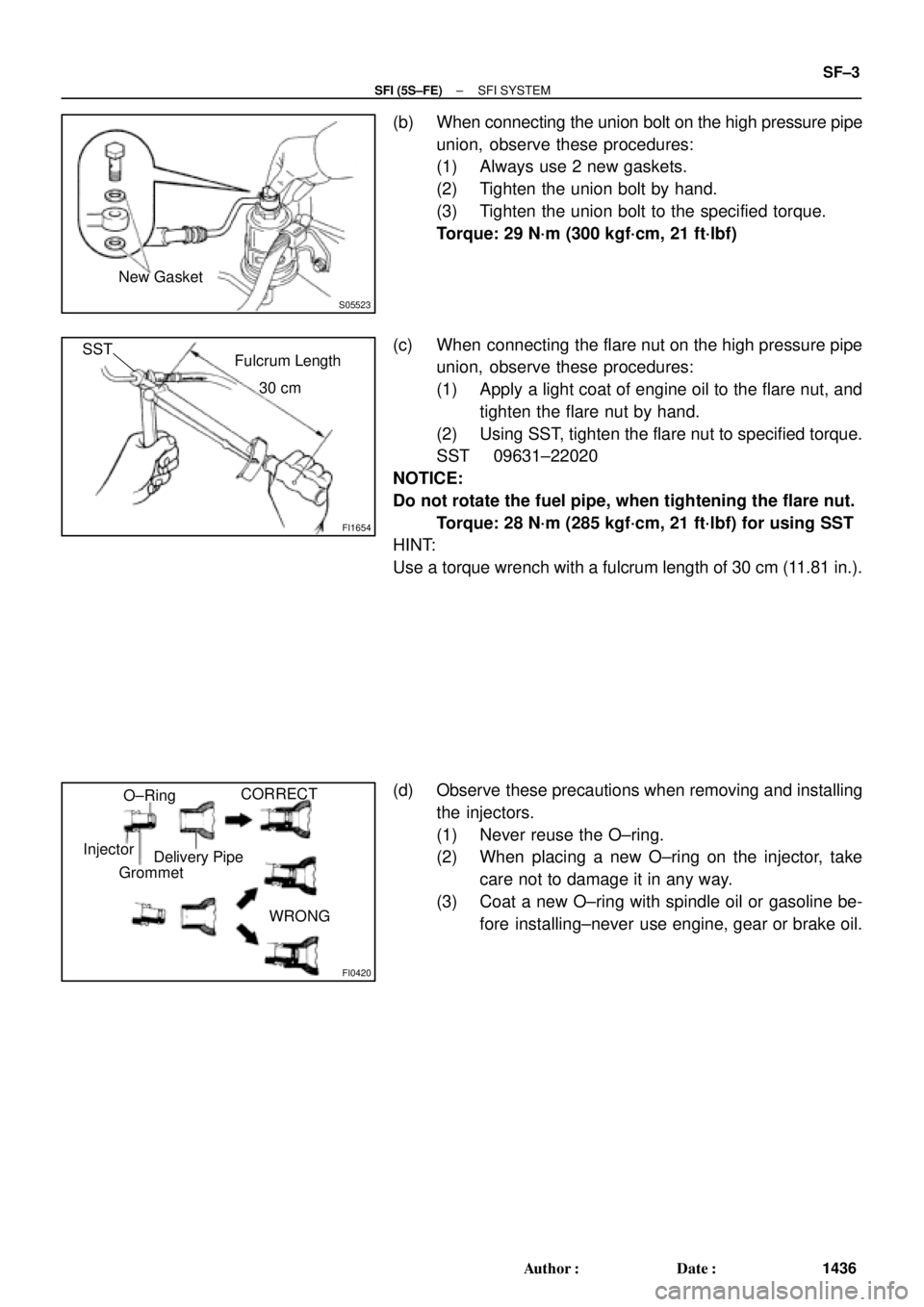
(b) When connecting the union bolt on the high pressure pipe
union, observe these procedures:
(1) Always use 2 new gaskets.
(2) Tighten the union bolt by hand.
(3) Tighten the union bolt to the specified torque.
Torque: 29 N´m (300 kgf´cm, 21 ft´lbf)
(c) When connecting the flare nut on the high pressure pipe
union, observe these procedures:
(1) Apply a light coat of engine oil to the flare nut, and
tighten the flare nut by hand.
(2) Using SST, tighten the flare nut to specified torque.
SST 09631±22020
NOTICE:
Do not rotate the fuel pipe, when tightening the flare nut.
Torque: 28 N´m (285 kgf´cm, 21 ft´lbf) for using SST
HINT:
Use a torque wrench with a fulcrum length of 30 cm (11.81 in.).
(d) Observe these precautions when removing and installing
the injectors.
(1) Never reuse the O±ring.
(2) When placing a new O±ring on the injector, take
care not to damage it in any way.
(3) Coat a new O±ring with spindle oil or gasoline be-
fore installing±never use engine, gear or brake oil.
Page 4103 of 4770
S05054
New Gasket
FI1654
Fulcrum Length
30 cm
SST
FI6372 FI6372
New O±Ring
Grommet
InjectorCORRECT
WRONG
± SFI (1MZ±FE)SFI SYSTEM
SF±3
1502 Author�: Date�:
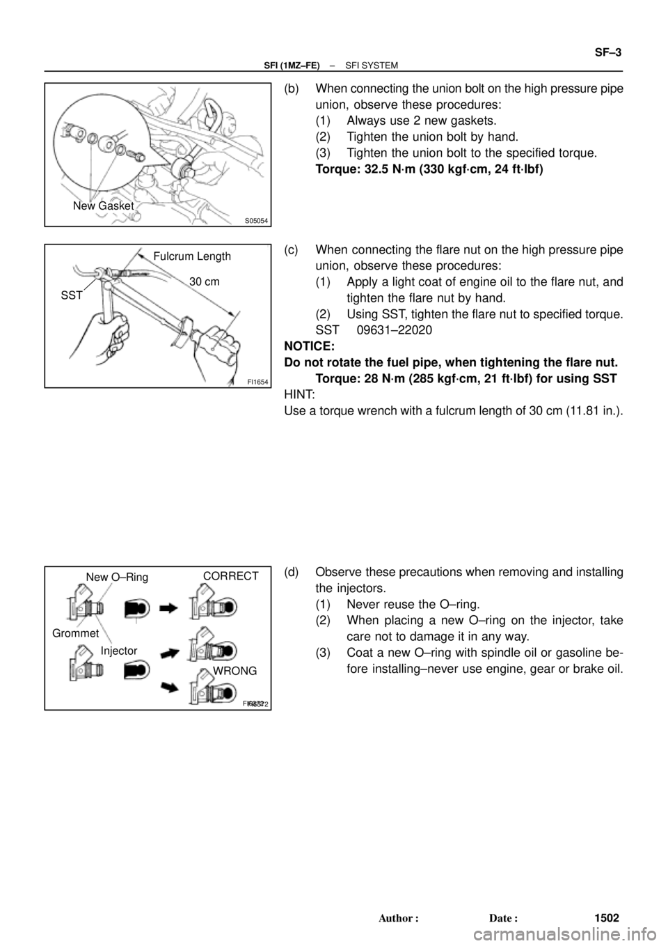
(b) When connecting the union bolt on the high pressure pipe
union, observe these procedures:
(1) Always use 2 new gaskets.
(2) Tighten the union bolt by hand.
(3) Tighten the union bolt to the specified torque.
Torque: 32.5 N´m (330 kgf´cm, 24 ft´lbf)
(c) When connecting the flare nut on the high pressure pipe
union, observe these procedures:
(1) Apply a light coat of engine oil to the flare nut, and
tighten the flare nut by hand.
(2) Using SST, tighten the flare nut to specified torque.
SST 09631±22020
NOTICE:
Do not rotate the fuel pipe, when tightening the flare nut.
Torque: 28 N´m (285 kgf´cm, 21 ft´lbf) for using SST
HINT:
Use a torque wrench with a fulcrum length of 30 cm (11.81 in.).
(d) Observe these precautions when removing and installing
the injectors.
(1) Never reuse the O±ring.
(2) When placing a new O±ring on the injector, take
care not to damage it in any way.
(3) Coat a new O±ring with spindle oil or gasoline be-
fore installing±never use engine, gear or brake oil.
Page 4548 of 4770
READINESS MONITOR DRIVE PATTERNS ± EG003-02 RevisedMarch 29, 2002
Page 17 of 23
Drive Pattern Preconditions
The monitor will not run unless:
�MIL is OFF.
�Fuel level is between 1/2 to 3/4 full (for faster completion)
.
�Altitude is 7800 feet (2400 m) or less.*
�ECT (Coolant Temp) is between 40�F and 95�F (4.4�C ± 35�C).
�IAT (Intake Air) is between 40�F and 95�F (4.4�C ± 35�C).*
�Cold Soak Procedure has been completed.
* For 2002 MY and later vehicles: The readiness test can be completed in cold ambient conditions
(less than 40�F / 4.4�C) and/or at high altitudes (more than 7800 feet / 2400 m) if the complete drive
pattern (including Cold Soak) is repeated a second time after cycling the ignition OFF.
NOTE:
Before starting the engine, the difference between ECT (Coolant Temp) and IAT (Intake
Air) must be less than 13�F (7�C). (Refer to Examples 1 and 2 on previous page.)
Drive Pattern Procedure
�Connect the OBDII Scantool to DLC3 to check monitor status and preconditions.
�Release the pressure in the fuel tank by removing and then reinstalling the fuel tank
cap.
2a. Start the engine and allow it to idle until ECT (Coolant Temp) is 167�F (75�C) or
greater. (See illustration on previous page.)
2b. Race the engine at 3,000 rpm for approximately 10 seconds. (See illustration on
previous page.)
2c. Allow the engine to idle with the A/C ON (to create a slight load) for 15 ± 50
minutes. (See illustration on previous page.)
NOTE:
If the vehicle is not equipped with A/C put a slight load on the engine by doing the
following:
�Securely set the parking brake.
�Block the drive wheels with wheel chocks.
�Allow the vehicle to idle in drive for 15 ± 50 minutes.
NOTE:
The readiness status may not switch to ªcompleteº after the first drive pattern trip if a
Pending Code has been set (first trip for a two±trip DTC).
�Pending Codes are available from the DTC Info Menu in Enhanced OBDII.
�Pending Codes indicate a POTENTIAL problem was detected. A second trip is
needed to confirm the DTC prior to diagnosis.
�Once a second trip is completed, a current DTC will be stored. Readiness
Monitor
Drive
Patterns:
EVAP
Monitors
(Continued)