Page 1535 of 4770
AC0LL±02
Z19146
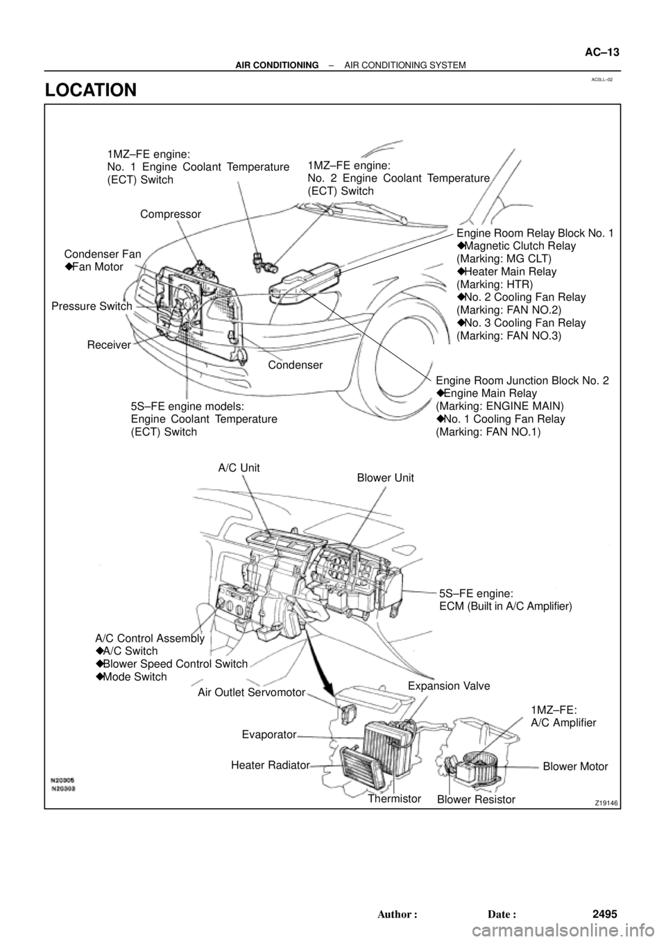
1MZ±FE engine:
No. 1 Engine Coolant Temperature
(ECT) Switch
Compressor
Engine Room Junction Block No. 2
� Engine Main Relay
(Marking: ENGINE MAIN)
� No. 1 Cooling Fan Relay
(Marking: FAN NO.1)Engine Room Relay Block No. 1
� Magnetic Clutch Relay
(Marking: MG CLT)
� Heater Main Relay
(Marking: HTR)
� No. 2 Cooling Fan Relay
(Marking: FAN NO.2)
� No. 3 Cooling Fan Relay
(Marking: FAN NO.3)
5S±FE engine models:
Engine Coolant Temperature
(ECT) Switch Receiver Pressure SwitchCondenser Fan
� Fan Motor1MZ±FE engine:
No. 2 Engine Coolant Temperature
(ECT) Switch
Condenser
Blower Unit A/C Unit
A/C Control Assembly
� A/C Switch
� Blower Speed Control Switch
� Mode Switch
Air Outlet Servomotor
Heater Radiator
Thermistor
Blower ResistorBlower Motor 1MZ±FE:
A/C Amplifier Expansion Valve5S±FE engine:
ECM (Built in A/C Amplifier)
Evaporator
± AIR CONDITIONINGAIR CONDITIONING SYSTEM
AC±13
2495 Author�: Date�:
LOCATION
Page 1537 of 4770

± AIR CONDITIONINGTROUBLESHOOTING
AC±15
2497 Author�: Date�:
Cool air comes out only at high engine rpm
1. Refrigerant volume
2. Drive belt
3. Magnetic clutch
4. Compressor
5. Condenser
6. Condenser fan
7. Receiver
8. Expansion valve
9. Evaporator
10.Thermistor
11. Refrigerant line
12.Pressure switch
13.*
1 ECM
*2 A/C amplifier
AC±3
AC±16
AC±16
AC±39
AC±52
AC±74
AC±49
AC±59
AC±30
AC±24
AC±21
AC±67
DI±218
AC±88
No engine idle±up when A/C switch ON
1. *1 ECM
*2 A/C amplifier
2. Wire harness
DI±218
AC±88
±
Blinking of A/C indicator
1. *1 ECM
*2 A/C amplifier
2. Thermistor
3. Compressor
DI±218
AC±88
AC±24
AC±39
A/C indicator does not lights up when turn mode switch to DEF.
position
1. A/C Fuse
2. Mode switch
3. A/C switch
4. *
1 ECM
*2 A/C amplifier
5. Wire harness
±
AC±84
AC±84
DI±218
AC±88
±
No warm air comes out
1. Engine coolant volume
2. A/C control assembly
3. Heater radiator±
AC±80
AC±57
No condenser fan operation
1. CDS FAN Fuse
2. Engine main relay
3. Cooling fan relay No. 1
4. Cooling fan relay No. 2
5. Cooling fan relay No. 3
6. Condenser fan motor
7. Pressure switch
8. *
1 Engine coolant temp. switch
*2 No. 1 Engine coolant temp. switch
9. *2No. 2 Engine coolant temp. switch
10.Wire harness
±
±
AC±72
AC±72
AC±72
AC±74
AC±67
AC±92
AC±92
AC±92
±
*1: 5S±FE Engine Models
*
2: 1MZ±FE Engine Models
Page 1548 of 4770
I07051
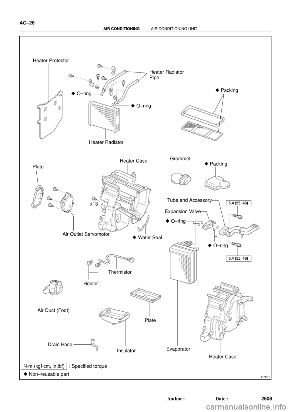
Heater Protector
Heater Radiator
Pipe
� Packing
� O±ring
� O±ring
Heater Radiator
Plate
Heater CaseGrommet
� Packing
x13
Air Outlet Servomotor� Water Seal
Air Duct (Foot)
Holder
Thermistor
5.4 (55, 48)
5.4 (55, 48)
� O±ring
� O±ring
Tube and Accessory
Expansion Valve
Drain Hose
Insulator
Plate
Evaporator
Heater Case
N´m (kgf´cm, in:lbf) : Specified torque
� Non±reusable part
AC±26
± AIR CONDITIONINGAIR CONDITIONING UNIT
2508 Author�: Date�:
Page 1549 of 4770

AC21W±01
N20288
N20237
Water Hose
MarkingUpper
LH
Hose ClipRH Heater Radiator Pipe
45 ± 10°
Lower
I09160
± AIR CONDITIONINGAIR CONDITIONING UNIT
AC±27
2509 Author�: Date�:
REMOVAL
1. DISCHARGE REFRIGERANT FROM REFRIGERATION
SYSTEM
HINT:
At the time of installation, please refer to the following item.
Evacuate air from refrigeration system.
Charge system with refrigerant and inspect for leakage of refrig-
erant.
Specified amount: 800 ± 50 g (28.22 ± 1.76 oz.)
2. DRAIN ENGINE COOLANT FROM RADIATOR
HINT:
It is not necessary to drain out all the coolant.
3. DISCONNECT WATER HOSE FROM HEATER RADIA-
TOR PIPES
(a) Using pliers, grip the claws of the hose clip and slide the
hose clip along the hose.
(b) Disconnect the water hose.
HINT:
At the time of installation, please refer to the following items.
�Push the water hose onto the heater radiator pipe as far
as ridge on the pipe and install the hose clip.
�Install the hose clip in a position, as shown in the illustra-
tion.
4. REMOVE BLOWER UNIT (See page AC±35)
5. REMOVE INSTRUMENT PANEL AND REINFORCE-
MENT (See page BO±75)
6. DISCONNECT LIQUID AND SUCTION TUBES
(a) Using SST, remove the 2 piping clamps.
SST 09870±00015 (Suction tube)
09870±00025 (Liquid tube)
Page 1551 of 4770
 Relea")
AC21X±01
N20287
N20283
N20243
x13Water Seal
Plate
EvaporatorInsurator
N20293
± AIR CONDITIONINGAIR CONDITIONING UNIT
AC±29
2511 Author�: Date�:
DISASSEMBLY
1. REMOVE AIR OUTLET SERVOMOTOR
(a) Release the claw and pull out the plate.
(b) Remove the 3 screws and servomotor.
2. REMOVE HEATER RADIATOR
(a) Remove the 3 screws and 3 plates.
(b) Remove the 2 clips and heater radiator pipes.
(c) Pull out the heater radiator.
3. REMOVE THESE FOOT AIR DUCT LH
4. REMOVE EXPANSION VALVE
(a) Remove piping clamp.
(b) Remove the packings.
(c) Using a hexagon wrench (5.0 mm, 0.20 in.), remove the
2 bolts and separate the expansion valve and evaporator.
5. REMOVE EVAPORATOR
(a) Remove the grommet from the evaporator.
(b) Using a knife, cut off each packings.
HINT:
Do not reuse the packing.
(c) Remove the 13 screws and separate the heater cases,
then remove the evaporator and water seal.
(d) Release the 4 claws and remove the plate from the evap-
orator.
6. PEEL OFF THE WATER SEAL FROM HEATER UNIT
7. REMOVE THERMISTOR
Pull out the thermistor with the holders.
Page 1554 of 4770
N20283
N20245
Pin
Pin AC±32
± AIR CONDITIONINGAIR CONDITIONING UNIT
2514 Author�: Date�:
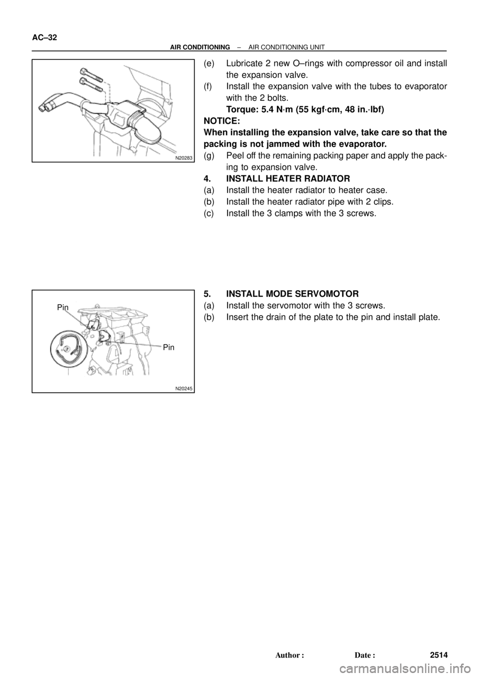
(e) Lubricate 2 new O±rings with compressor oil and install
the expansion valve.
(f) Install the expansion valve with the tubes to evaporator
with the 2 bolts.
Torque: 5.4 N´m (55 kgf´cm, 48 in.´lbf)
NOTICE:
When installing the expansion valve, take care so that the
packing is not jammed with the evaporator.
(g) Peel off the remaining packing paper and apply the pack-
ing to expansion valve.
4. INSTALL HEATER RADIATOR
(a) Install the heater radiator to heater case.
(b) Install the heater radiator pipe with 2 clips.
(c) Install the 3 clamps with the 3 screws.
5. INSTALL MODE SERVOMOTOR
(a) Install the servomotor with the 3 screws.
(b) Insert the drain of the plate to the pin and install plate.
Page 1572 of 4770

AC0MB±02
N20279
AC±50
± AIR CONDITIONINGRECEIVER
2532 Author�: Date�:
REMOVAL
1. DISCHARGE REFRIGERANT FROM REFRIGERATION
SYSTEM
HINT:
At the time of installation, please refer to the following item.
Evacuate air from refrigeration system.
Charge system with refrigerant and inspect for leakage of refrig-
erant.
Specified amount: 800 ± 50 g (28.22 ± 1.76 oz.)
2. REMOVE RADIATOR UPPER SUPPORT SEAL
3. DISCONNECT 2 LIQUID TUBES FROM RECEIVER
Remove the 2 bolts and both tubes.
Torque: 5.4 N´m (55 kgf´cm, 48 in.´lbf)
NOTICE:
Cap the open fittings immediately to keep moisture or dirt
out of the system.
HINT:
At the time of installation, please refer to the following item.
Lubricate 2 new O±rings with compressor oil and install the
tubes.
4. REMOVE RECEIVER
(a) Remove the holder bolt and pull out receiver downward.
HINT:
At the time of installation, please refer to the following item.
If receiver was replaced, add compressor oil to compressor.
Add 20 cc (0.71 fl.oz.)
Compressor oil: ND±OIL 8 or equivalent
(b) Remove the 2 bolts and holder.
Page 1575 of 4770

AC0ME±02
I03836
± AIR CONDITIONINGCONDENSER
AC±53
2535 Author�: Date�:
REMOVAL
1. DISCHARGE REFRIGERANT FROM REFRIGERATION
SYSTEM
HINT:
At the time of installation, please refer to the following item.
Evacuate air from refrigeration system.
Charge system with refrigerant and inspect for leakage of refrig-
erant.
Specified amount: 800 ± 50 g (28.22 ± 1.76 oz.)
2. REMOVE UPPER RADIATOR SUPPORTS
3. REMOVE RECEIVER AND HOLDER
(See page AC±50)
4. DISCONNECT DISCHARGE HOSE
Loosen the nut and disconnect the discharge hose.
Torque: 10 N´m (100 kgf´cm, 7 ft´lbf)
NOTICE:
Cap the open fittings immediately to keep moisture or dirt
out of the system.
HINT:
At the time of installation, please refer to the following item.
Lubricate a new O±ring with compressor oil and install the tube.
5. REMOVE LIQUID TUBE
Loosen the nut and remove the liquid tube.
Torque: 14 N´m (140 kgf´cm, 10 ft´lbf)
NOTICE:
Cap the open fittings immediately to keep moisture or dirt
out of the system.
HINT:
At the time of installation, please refer to the following item.
Lubricate a new O±ring with compressor oil and install the tube.