Page 1576 of 4770
N20451
AC±54
± AIR CONDITIONINGCONDENSER
2536 Author�: Date�:
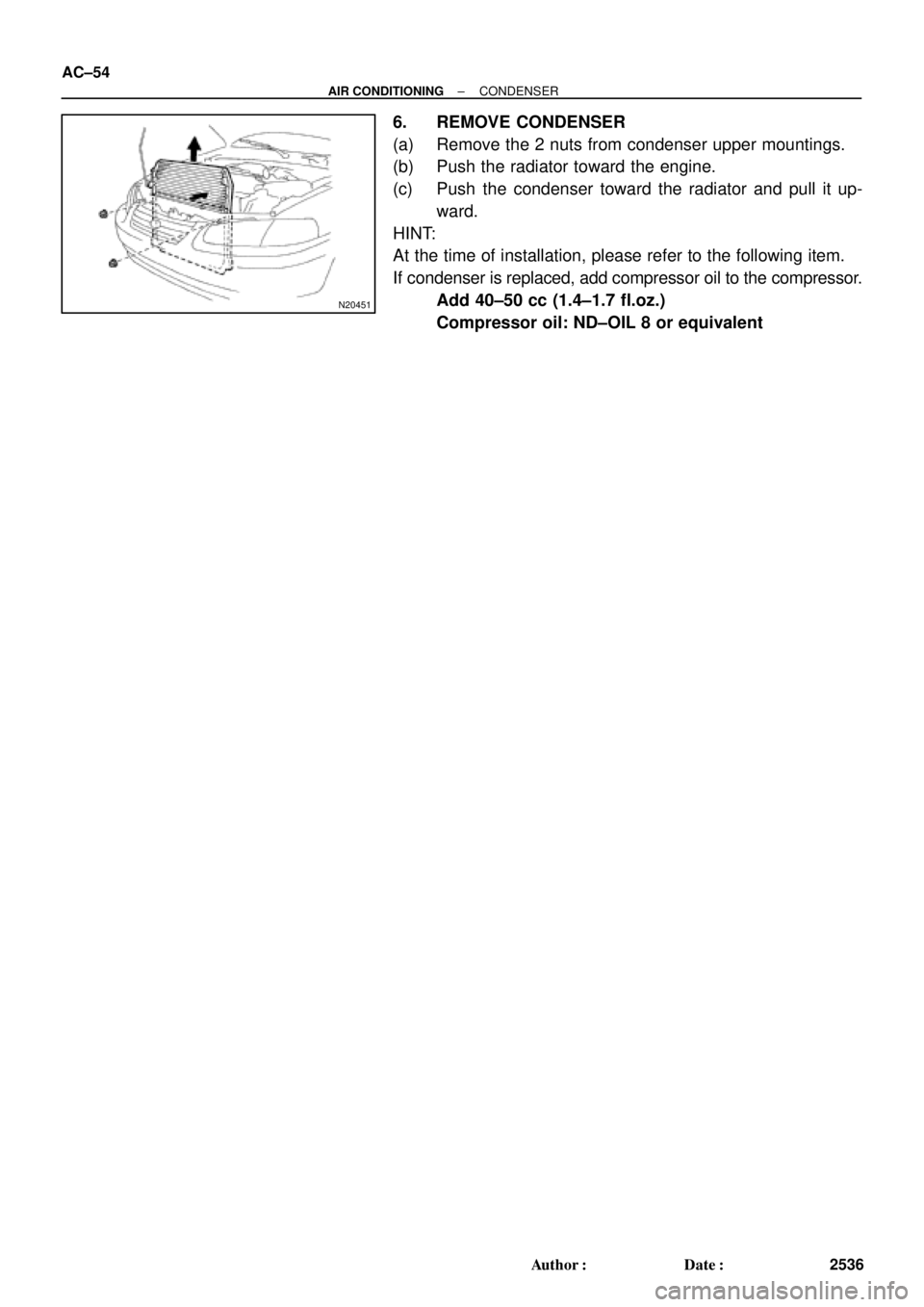
6. REMOVE CONDENSER
(a) Remove the 2 nuts from condenser upper mountings.
(b) Push the radiator toward the engine.
(c) Push the condenser toward the radiator and pull it up-
ward.
HINT:
At the time of installation, please refer to the following item.
If condenser is replaced, add compressor oil to the compressor.
Add 40±50 cc (1.4±1.7 fl.oz.)
Compressor oil: ND±OIL 8 or equivalent
Page 1578 of 4770
AC21Z±01
N20692
I09156
I09155
I09154
AC±56
± AIR CONDITIONINGHEATER RADIATOR
2538 Author�: Date�:
HEATER RADIATOR
REMOVAL
1. DRAIN ENGINE COOLANT FROM RADIATOR
HINT:
It is not necessary to drain out all the coolant.
2. DISCONNECT WATER HOSES FROM A/C UNIT
(See page AC±27)
3. REMOVE NO. 1 LOWER INSTRUMENT PANEL
4. REMOVE LH INSTRUMENT LOWER PANEL
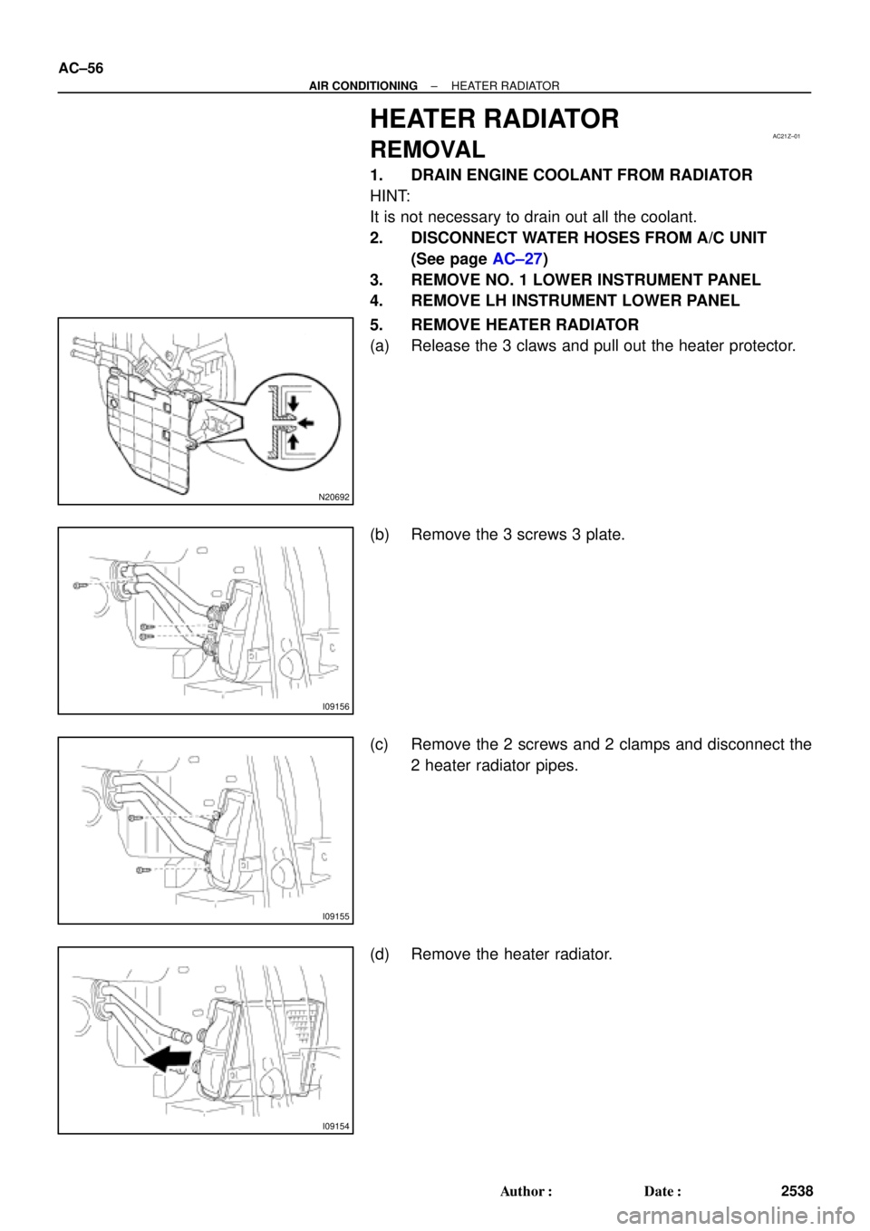
5. REMOVE HEATER RADIATOR
(a) Release the 3 claws and pull out the heater protector.
(b) Remove the 3 screws 3 plate.
(c) Remove the 2 screws and 2 clamps and disconnect the
2 heater radiator pipes.
(d) Remove the heater radiator.
Page 1579 of 4770
AC0MK±01
± AIR CONDITIONINGHEATER RADIATOR
AC±57
2539 Author�: Date�:
INSPECTION
INSPECT FINS FOR BLOCKAGE
If the fins are clogged, clean them with compressed air.
Page 1580 of 4770
AC0ML±01
AC±58
± AIR CONDITIONINGHEATER RADIATOR
2540 Author�: Date�:
INSTALLATION
Installation is in the reverse order of removal (See page AC±56).
Page 1597 of 4770
AC0N7±02
Z19147
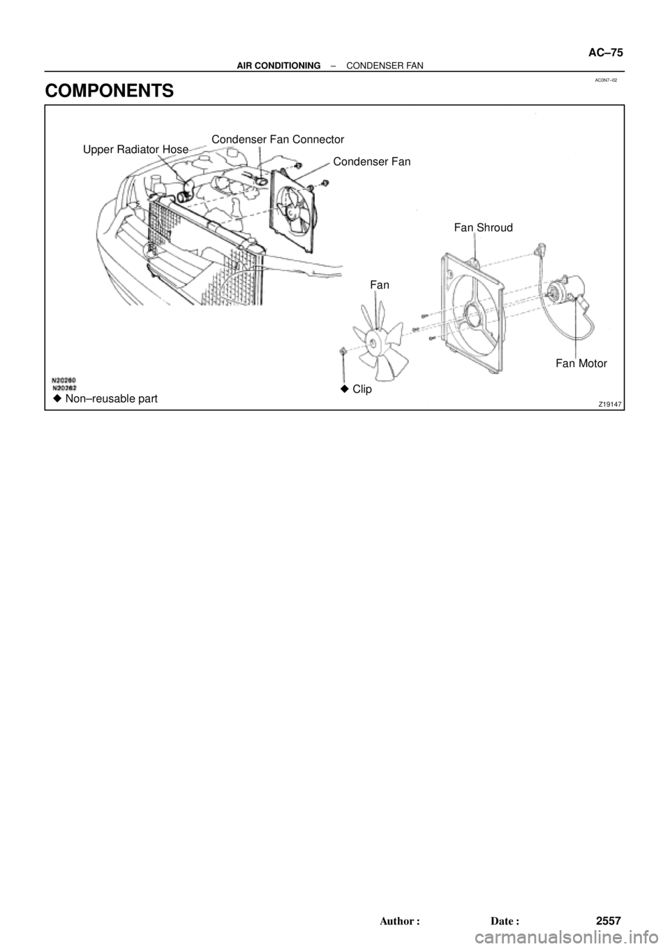
Upper Radiator Hose
Fan Condenser Fan Connector
Fan Motor Condenser Fan
� Non±reusable partFan Shroud
� Clip
± AIR CONDITIONINGCONDENSER FAN
AC±75
2557 Author�: Date�:
COMPONENTS
Page 1598 of 4770
AC0N8±02
AC±76
± AIR CONDITIONINGCONDENSER FAN
2558 Author�: Date�:
REMOVAL
1. 1MZ±FE engine models only:
DRAIN ENGINE COOLANT FROM RADIATOR
HINT:
It is not necessary to drain out all the coolant.
2. 1MZ±FE engine models only:
DISCONNECT UPPER RADIATOR HOSE
3. REMOVE CONDENSER FAN
(a) Disconnect the connector.
(b) Remove the 4 bolts and fan.
Page 1614 of 4770
 SWITCH
2574 Author�: Date�:
ENGINE COOLANT")
AC227±01
P15233
5S±FE:
ECT Switch
P19584
1MZ±FE:No. 1 ECT Switch
No. 2 ECT Switch
P01924
P01924
AC±92
± AIR CONDITIONINGENGINE COOLANT TEMPERATURE (ECT) SWITCH
2574 Author�: Date�:
ENGINE COOLANT
TEMPERATURE (ECT) SWITCH
INSPECTION
1. DRAIN ENGINE COOLANT FROM RADIATOR
HINT:
It is not necessary to drain out all the coolant.
2. REMOVE ECT SWITCHES
(a) Disconnect the connector.
(b) Remove the ECT switch.
3. 5S±FE engine:
INSPECT ECT SWITCH CONTINUITY
(a) Using an ohmmeter, check that no continuity exists be-
tween the terminals when the coolant temperature is
above 93°C (199°F).
If continuity exists, replace the switch.
(b) Using an ohmmeter, check that continuity exists between
the terminals when the coolant temperature is below
83°C (181°F).
If no continuity exists, replace the switch.
4. 1MZ±FE engine:
INSPECT No. 1 SWITCH CONTINUITY
(a) Using an ohmmeter, check that no continuity exists be-
tween the terminals when the coolant temperature is
above 98°C (208°F).
If continuity exists, replace the switch.
(b) Using an ohmmeter, check that continuity exists between
the terminals when the coolant temperature is below
88°C (190°F).
If no continuity exists, replace the switch.
Page 1963 of 4770
BO0KV±01
H01708
Turn Signal Light Assembly
Upper Reinforcement
Sub±AssemblyTurn Signal Light Assembly
Fender Liner Front Bumper
Reinforcement
Energy Absorber
Mounting Plate
Front Bumper
Energy Absorber
Engine Under Cover Bumper Cover Emblem,
Radiator GrillFender Liner
N´m (kgf´cm, ft´lbf) : Specified torque
5.5 (55, 49 in.´lbf)34 (350, 25)
Clip
34 (350, 25)
No.2
Reinforcement
Clip BO±4
± BODYFRONT BUMPER
2352 Author�: Date�:
FRONT BUMPER
COMPONENTS