Page 3363 of 4770
EC03E±05
B01082B04812B06707
Type A
Type BGasket
Gasket
B06544
Vacuum
Gauge
S05331
EC±6
± EMISSION CONTROL (5S±FE)EVAPORATIVE EMISSION (EVAP) CONTROL SYSTEM
1404 Author�: Date�:
INSPECTION
1. INSPECT LINES AND CONNECTORS
Visually check for loose connections, sharp bends or damage.
2. INSPECT FUEL TANK FILLER PIPE
Visually check for deformation, cracks or fuel leakage.
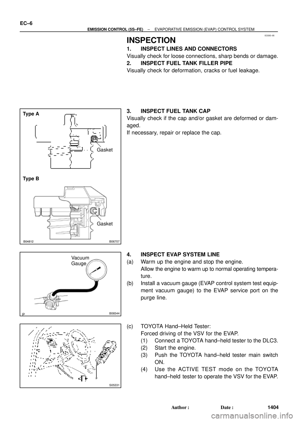
3. INSPECT FUEL TANK CAP
Visually check if the cap and/or gasket are deformed or dam-
aged.
If necessary, repair or replace the cap.
4. INSPECT EVAP SYSTEM LINE
(a) Warm up the engine and stop the engine.
Allow the engine to warm up to normal operating tempera-
ture.
(b) Install a vacuum gauge (EVAP control system test equip-
ment vacuum gauge) to the EVAP service port on the
purge line.
(c) TOYOTA Hand±Held Tester:
Forced driving of the VSV for the EVAP.
(1) Connect a TOYOTA hand±held tester to the DLC3.
(2) Start the engine.
(3) Push the TOYOTA hand±held tester main switch
ON.
(4) Use the ACTIVE TEST mode on the TOYOTA
hand±held tester to operate the VSV for the EVAP.
Page 3380 of 4770
EC0AV±01
B01082B04812B06707
Type A
Type BGasket
Gasket
B06544
Vacuum
Gauge
S05331
TOYOTA
Hand±Held Tester
DLC3
EC±6
± EMISSION CONTROL (1MZ±FE)EVAPORATIVE EMISSION (EVAP) CONTROL SYSTEM
1421 Author�: Date�:
INSPECTION
1. INSPECT LINES AND CONNECTORS
Visually check for loose connections, sharp bends or damage.
2. INSPECT FUEL TANK FILLER PIPE
Visually check for deformation, cracks or fuel leakage.
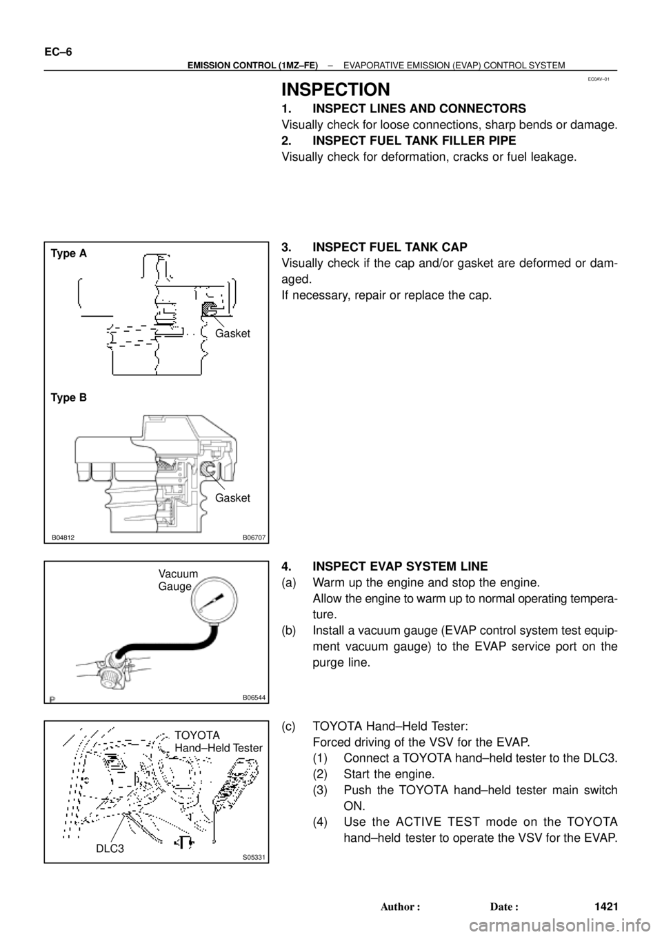
3. INSPECT FUEL TANK CAP
Visually check if the cap and/or gasket are deformed or dam-
aged.
If necessary, repair or replace the cap.
4. INSPECT EVAP SYSTEM LINE
(a) Warm up the engine and stop the engine.
Allow the engine to warm up to normal operating tempera-
ture.
(b) Install a vacuum gauge (EVAP control system test equip-
ment vacuum gauge) to the EVAP service port on the
purge line.
(c) TOYOTA Hand±Held Tester:
Forced driving of the VSV for the EVAP.
(1) Connect a TOYOTA hand±held tester to the DLC3.
(2) Start the engine.
(3) Push the TOYOTA hand±held tester main switch
ON.
(4) Use the ACTIVE TEST mode on the TOYOTA
hand±held tester to operate the VSV for the EVAP.
Page 3539 of 4770
S04790
Chamber Stay
Engine
HangerEGR
Pipe
S04791
8 mm Hexagon
Wrench
A01807
(b)
(c)
A01808
± ENGINE MECHANICAL (1MZ±FE)CYLINDER HEAD
EM±33
1319 Author�: Date�:
(t) Disconnect the engine wire clamp from the emission con-
trol valve set.
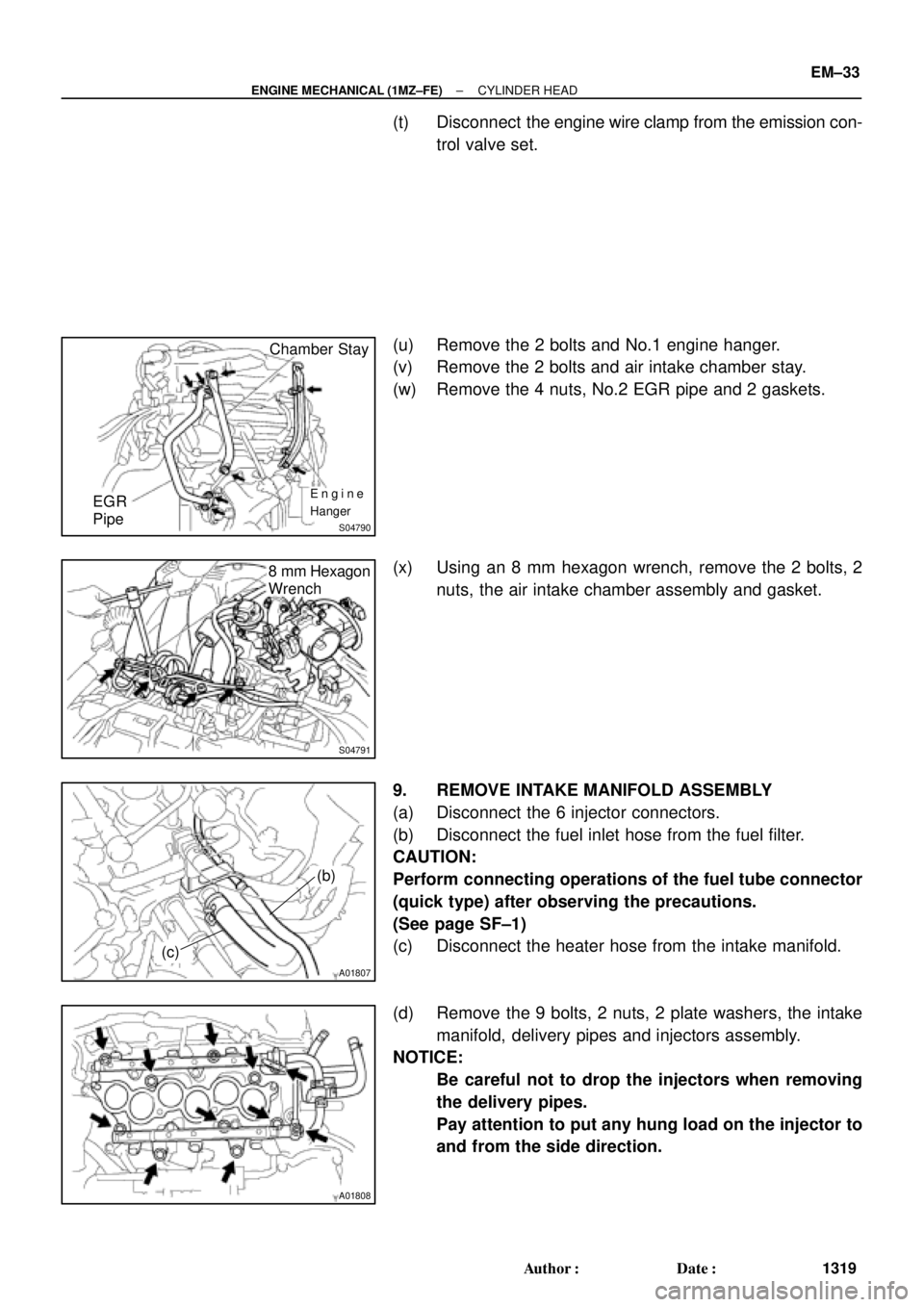
(u) Remove the 2 bolts and No.1 engine hanger.
(v) Remove the 2 bolts and air intake chamber stay.
(w) Remove the 4 nuts, No.2 EGR pipe and 2 gaskets.
(x) Using an 8 mm hexagon wrench, remove the 2 bolts, 2
nuts, the air intake chamber assembly and gasket.
9. REMOVE INTAKE MANIFOLD ASSEMBLY
(a) Disconnect the 6 injector connectors.
(b) Disconnect the fuel inlet hose from the fuel filter.
CAUTION:
Perform connecting operations of the fuel tube connector
(quick type) after observing the precautions.
(See page SF±1)
(c) Disconnect the heater hose from the intake manifold.
(d) Remove the 9 bolts, 2 nuts, 2 plate washers, the intake
manifold, delivery pipes and injectors assembly.
NOTICE:
�Be careful not to drop the injectors when removing
the delivery pipes.
�Pay attention to put any hung load on the injector to
and from the side direction.
Page 3573 of 4770
S04791
8 mm Hexagon
Wrench
S04790
Chamber Stay
Engine
Hanger EGR
Pipe
± ENGINE MECHANICAL (1MZ±FE)CYLINDER HEAD
EM±67
1353 Author�: Date�:
(b) Connect the fuel inlet hose to the fuel filter.
CAUTION:
Perform connecting operations of the fuel tube connector
(quick type) after observing the precaution.
(See page SF±1)
(c) Connect the heater hose to the intake manifold.
29. RETIGHTEN WATER OUTLET MOUNTING BOLTS
AND NUTS
Tighten the 2 bolts and 2 nuts.
Torque: 15 N´m (150 kgf´cm, 11 ft´lbf)
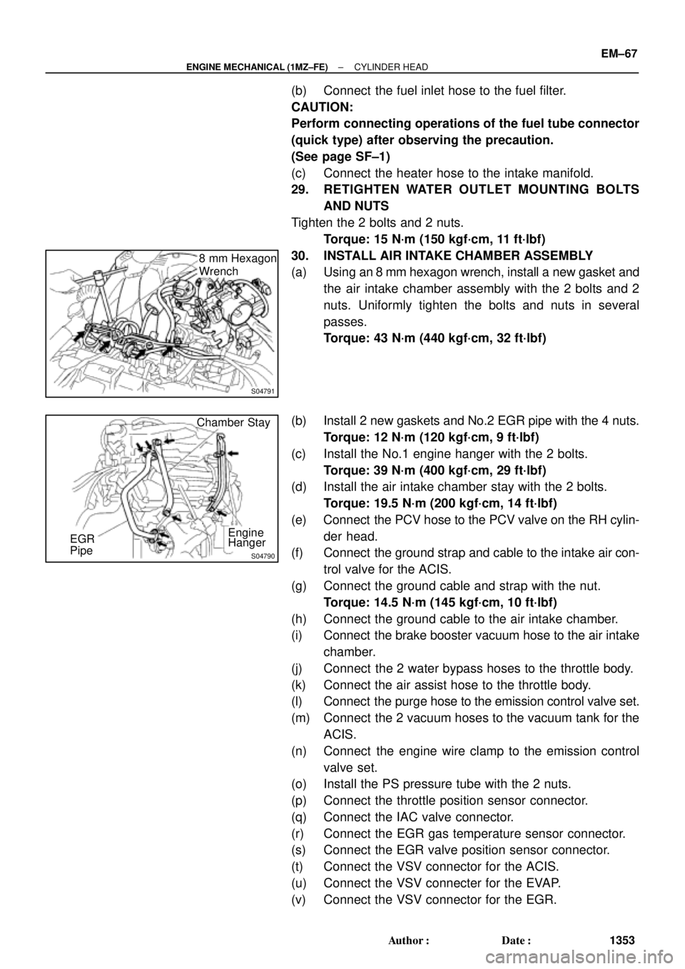
30. INSTALL AIR INTAKE CHAMBER ASSEMBLY
(a) Using an 8 mm hexagon wrench, install a new gasket and
the air intake chamber assembly with the 2 bolts and 2
nuts. Uniformly tighten the bolts and nuts in several
passes.
Torque: 43 N´m (440 kgf´cm, 32 ft´lbf)
(b) Install 2 new gaskets and No.2 EGR pipe with the 4 nuts.
Torque: 12 N´m (120 kgf´cm, 9 ft´lbf)
(c) Install the No.1 engine hanger with the 2 bolts.
Torque: 39 N´m (400 kgf´cm, 29 ft´lbf)
(d) Install the air intake chamber stay with the 2 bolts.
Torque: 19.5 N´m (200 kgf´cm, 14 ft´lbf)
(e) Connect the PCV hose to the PCV valve on the RH cylin-
der head.
(f) Connect the ground strap and cable to the intake air con-
trol valve for the ACIS.
(g) Connect the ground cable and strap with the nut.
Torque: 14.5 N´m (145 kgf´cm, 10 ft´lbf)
(h) Connect the ground cable to the air intake chamber.
(i) Connect the brake booster vacuum hose to the air intake
chamber.
(j) Connect the 2 water bypass hoses to the throttle body.
(k) Connect the air assist hose to the throttle body.
(l) Connect the purge hose to the emission control valve set.
(m) Connect the 2 vacuum hoses to the vacuum tank for the
ACIS.
(n) Connect the engine wire clamp to the emission control
valve set.
(o) Install the PS pressure tube with the 2 nuts.
(p) Connect the throttle position sensor connector.
(q) Connect the IAC valve connector.
(r) Connect the EGR gas temperature sensor connector.
(s) Connect the EGR valve position sensor connector.
(t) Connect the VSV connector for the ACIS.
(u) Connect the VSV connecter for the EVAP.
(v) Connect the VSV connector for the EGR.
Page 3578 of 4770
S04497
B00881
Connector
Bracket
EM±72
± ENGINE MECHANICAL (1MZ±FE)ENGINE UNIT
1358 Author�: Date�:
(k) Disconnect the brake booster vacuum hose from the air
intake chamber.
(l) Disconnect the engine coolant reservoir hose from the
water outlet.
(m) Disconnect the heater hose from the intake manifold.
(n) Disconnect the heater hose from the water inlet housing.
(o) Disconnect the fuel inlet hose from the fuel filter.
CAUTION:
Perform disconnecting operation of the fuel tube connec-
tor (quick type) after observing the precautions.
(See page SF±6)
(p) Disconnect the purge hose from the pipe on the emission
control valve set.
(q) Disconnect the 2 vacuum hoses from the vacuum tank for
the ACIS.
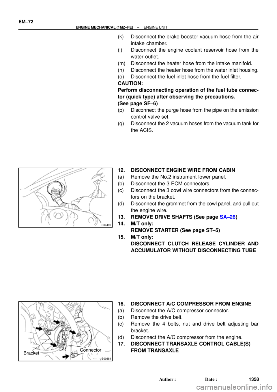
12. DISCONNECT ENGINE WIRE FROM CABIN
(a) Remove the No.2 instrument lower panel.
(b) Disconnect the 3 ECM connectors.
(c) Disconnect the 3 cowl wire connectors from the connec-
tors on the bracket.
(d) Disconnect the grommet from the cowl panel, and pull out
the engine wire.
13. REMOVE DRIVE SHAFTS (See page SA±26)
14. M/T only:
REMOVE STARTER (See page ST±5)
15. M/T only:
DISCONNECT CLUTCH RELEASE CYLINDER AND
ACCUMULATOR WITHOUT DISCONNECTING TUBE
16. DISCONNECT A/C COMPRESSOR FROM ENGINE
(a) Disconnect the A/C compressor connector.
(b) Remove the drive belt.
(c) Remove the 4 bolts, nut and drive belt adjusting bar
bracket.
(d) Disconnect the A/C compressor from the engine.
17. DISCONNECT TRANSAXLE CONTROL CABLE(S)
FROM TRANSAXLE
Page 3585 of 4770
S05048
± ENGINE MECHANICAL (1MZ±FE)ENGINE UNIT
EM±79
1365 Author�: Date�:
(f) Connect the 2 ground strap connectors to the LH fender
apron.
(g) Connect the DLC1 to the RH fender apron.
(h) Connect the ground cable to the battery body bracket.
(i) Connect the engine wire protector clamp to the battery
body bracket.
(j) Connect the engine wire clamp to the bracket on the RH
fender apron.
(k) Connect the engine wire clamp to the bracket on the fuel
filter.
(l) Connect the brake booster vacuum hose to the air intake
chamber.
(m) Connect the engine coolant reservoir hose to the water
outlet.
(n) Connect the heater hose to the intake manifold.
(o) Connect the heater hose to the water inlet housing.
(p) Connect the fuel inlet hose to the fuel filter.
CAUTION:
Perform connecting operations of the fuel tube connector
(quick type) after observing the precautions.
(See page SF±6)
(q) Connect the purge hose to the pipe on the emission con-
trol valve set.
(r) Connect the 2 vacuum hoses to the vacuum tank for the
ACIS.
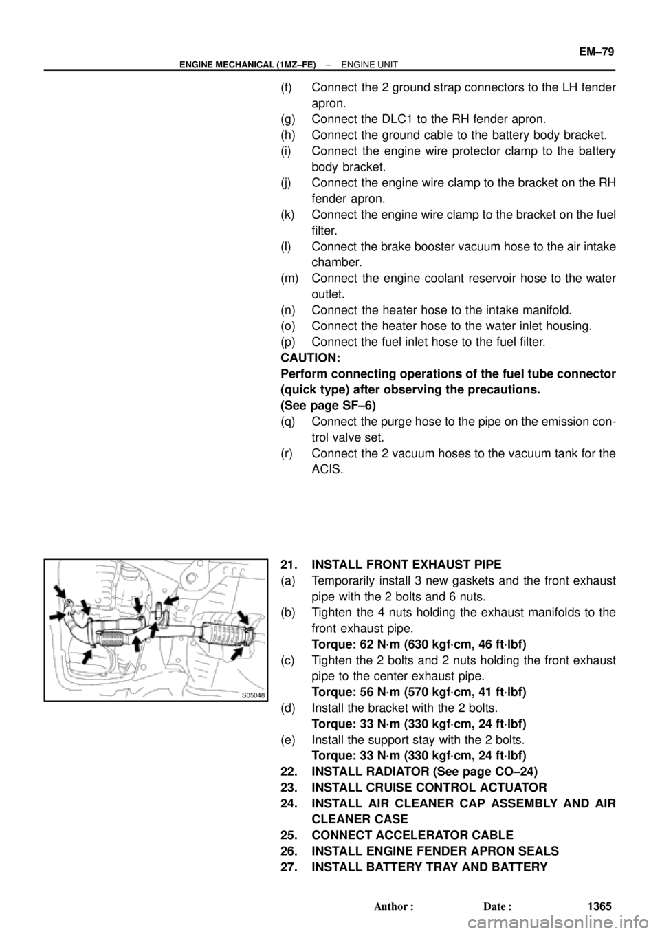
21. INSTALL FRONT EXHAUST PIPE
(a) Temporarily install 3 new gaskets and the front exhaust
pipe with the 2 bolts and 6 nuts.
(b) Tighten the 4 nuts holding the exhaust manifolds to the
front exhaust pipe.
Torque: 62 N´m (630 kgf´cm, 46 ft´lbf)
(c) Tighten the 2 bolts and 2 nuts holding the front exhaust
pipe to the center exhaust pipe.
Torque: 56 N´m (570 kgf´cm, 41 ft´lbf)
(d) Install the bracket with the 2 bolts.
Torque: 33 N´m (330 kgf´cm, 24 ft´lbf)
(e) Install the support stay with the 2 bolts.
Torque: 33 N´m (330 kgf´cm, 24 ft´lbf)
22. INSTALL RADIATOR (See page CO±24)
23. INSTALL CRUISE CONTROL ACTUATOR
24. INSTALL AIR CLEANER CAP ASSEMBLY AND AIR
CLEANER CASE
25. CONNECT ACCELERATOR CABLE
26. INSTALL ENGINE FENDER APRON SEALS
27. INSTALL BATTERY TRAY AND BATTERY
Page 3710 of 4770

± INTRODUCTIONTERMS
IN±39
39 Author�: Date�:
OHVOverhead Valve
OPTOption
O/SOversize
P & BVProportioning And Bypass Valve
PCSPower Control System
PCVPositive Crankcase Ventilation
PKBParking Brake
PPSProgressive Power Steering
PSPower Steering
PTOPower Take±Off
R & PRack And Pinion
R/BRelay Block
RBSRecirculating Ball Type Steering
R/FReinforcement
RFSRigid Front Suspension
RRSRigid Rear Suspension
RHRight±Hand
RHDRight±Hand Drive
RLYRelay
ROMRead Only Memory
RrRear
RRRear±Engine Rear±Wheel Drive
RWDRear±Wheel Drive
SDNSedan
SENSensor
SICSStarting Injection Control System
SOCState Of Charge
SOHCSingle Overhead Camshaft
SPECSpecification
SPISingle Point Injection
SRSSupplemental Restraint System
SSMSpecial Service Materials
SSTSpecial Service Tools
STDStandard
STJCold±Start Fuel Injection
SWSwitch
SYSSystem
T/ATransaxle
TACHTachometer
TBIThrottle Body Electronic Fuel Injection
TCTurbocharger
TCCSTOYOTA Computer±Controlled System
TCVTiming Control Valve
TDCTop Dead Center
TEMP.Temperature
TEMSTOYOTA Electronic Modulated Suspension
Page 3982 of 4770
SS0AH±03
SS±20
± SERVICE SPECIFICATIONSSFI (5S±FE)
183 Author�: Date�:
TORQUE SPECIFICATION
Part tightenedN´mkgf´cmft´lbf
Fuel line
Union bolt type
Flare nut type for use with SST
29
28
300
285
21
21
Fuel pump assembly x Fuel tank44035 in.´lbf
Fuel filter x Fuel pump bracket22017 in.´lbf
Fuel pressure regulator x Fuel pump bracket22017 in.´lbf
Delivery pipe x Cylinder head131309
Fuel tank band x Body3940029
Throttle body x Intake manifold1919514
Knock sensor 1 x Cylinder block4445032
A/F sensor x Exhaust manifold4445032
Oxygen sensor (bank 1 sensor 1) x Exhaust manifold4445032
Oxygen sensor (bank 1 sensor 2) x Front exhaust pipe4445032