Page 238 of 447

7F-16 REAR DIFFERENTIAL
8) Place zero-adjusted mounting dummy (1) and dial gauge set
on pinion dummy (2) and take measurement between zero
position and extended dial gauge measuring tip.
9) Obtain adjusting shim thickness by using measured value by
dial gauge in the following equation.
10) Select adjusting shim(s) (1) closest to calculated value from
among following available sizes and put it in place and then
press-fit rear bearing.
Special tool
(A) : 09913-80112
Available shim thickness
“a” : 0.30, 1.00, 1.03, 1.06, 1.09, 1.12, 1.15, 1.18, 1.21, 1.24,
1.27, and 1.30 mm (0.012, 0.039, 0.041, 0.042, 0.043, 0.044,
0.045, 0.046, 0.048, 0.049, 0.050 and 0.051 in.)
11) With new pinion spacer (3) inserted as shown, install front
bearing to differential carrier. NOTE:
Repeat turning back and forth of dummy and measure
distance as far as top surface of pinion dummy accu-
rately.
When dial gauge measuring tip extends from 0 (zero)
position, pointer turns counterclockwise.
Measured value may exceed 1 mm. Therefore, it is also
necessary to know reading of short pointer.
Necessary shim thickness = Dial gauge measured value C
1. Drive bevel pinion mounting dummy
2. Drive bevel pinion dummy
C
1
2
NOTE:
Make sure to use new spacer for reinstallation.
Apply oil to bearings.
1. Drive bevel pinion
2. Rear bearing
Page 239 of 447

REAR DIFFERENTIAL 7F-17
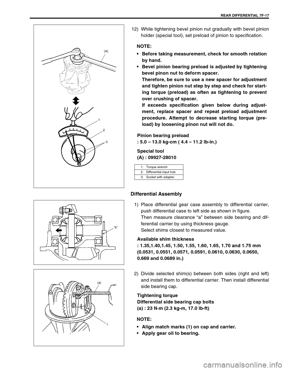
12) While tightening bevel pinion nut gradually with bevel pinion
holder (special tool), set preload of pinion to specification.
Pinion bearing preload
: 5.0 – 13.0 kg-cm ( 4.4 – 11.2 lb-in.)
Special tool
(A) : 09927-28010
Differential Assembly
1) Place differential gear case assembly to differential carrier,
push differential case to left side as shown in figure.
Then measure clearance “a” between side bearing and dif-
ferential carrier by using thickness gauge.
Select shims closest to measured value.
Available shim thickness
: 1.35,1.40,1.45, 1.50, 1.55, 1.60, 1.65, 1.70 and 1.75 mm
(0.0531, 0.0551, 0.0571, 0.0591, 0.0610, 0.0630, 0.0650,
0.669 and 0.0689 in.)
2) Divide selected shim(s) between both sides (right and left)
and install them to differential carrier. Then install differential
side bearing cap.
Tightening torque
Differential side bearing cap bolts
(a) : 23 N·m (2.3 kg-m, 17.0 lb-ft) NOTE:
Before taking measurement, check for smooth rotation
by hand.
Bevel pinion bearing preload is adjusted by tightening
bevel pinon nut to deform spacer.
Therefore, be sure to use a new spacer for adjustment
and tighten pinion nut step by step and check for start-
ing torque (preload) as often as tightening to prevent
over crushing of spacer.
If exceeds specification given below during adjust-
ment, replace spacer and repeat preload adjustment
procedure. Attempt to decrease starting torque (pre-
load) by loosening pinon nut will not do.
1. Torque wrench
2. Differential input hub
3. Socket with adapter
NOTE:
Align match marks (1) on cap and carrier.
Apply gear oil to bearing.
Page 240 of 447

7F-18 REAR DIFFERENTIAL
3) Measure backlash by using dial gauge.
Drive bevel gear backlash
: 0.10 – 0.20 mm (0.0039 – 0.0078 in.)
Special tool
(A) : 09900-20606
(B) : 09900-20701
4) Check gear tooth contact as follows.
a) After cleaning tooth surface of drive bevel gears, paint them
with gear marking compound evenly by using brush or
sponge etc.
b) Turn gear to bring its painted part in mesh with bevel pinion
and turn it back and forth by hand to repeat their contact.
c) Bring painted part up and check contact pattern, referring to
the following chart. If contact pattern is not normal, readjust
or replace as necessary according to instruction in chart.
5) After completing of gear tooth contact check caulk bevel pin-
ion nut with caulking tool and hammer. NOTE:
Be sure to apply measuring tip of dial gauge at right
angles to convex side (drive side) of tooth.
If backlash is out of specification, change division of
shims so that backlash is within specification.
CAUTION:
When applying red lead paste to teeth, be sure to paint
tooth surfaces uniformly. The paste must not be too dry
or too fluid.
NOTE:
Be careful not to turn bevel gear more than one full revo-
lution, for it will hinder accurate check.
Page 241 of 447
REAR DIFFERENTIAL 7F-19
TOOTH CONTACT PATTERN DIAGNOSIS AND REMEDY
NORMAL
HIGH CONTACT
Pinion is positioned too fat from the
center of drive bevel gear.
1) Increase thickness of pinion height
adjusting shim and position pinion
closer to gear center.
2) Adjust drive bevel gear backlash to
specification.
LOW CONTACT
Pinion is positioned too close to the
center of drive bevel gear.
1) Decrease thickness of pinion height
adjusting shim and position pinion
farther from gear center.
2) Adjust drive bevel gear backlash to
specification.
These contact patterns indicate that the “offset” of dif-
ferential is too much or too little. The remedy is to
replace the carrier with a new one.
These contact patterns, located on toe or heel on both
drive and coast sides, mean that 1) both pinion and
gear are defective, 2) carrier is not true and square, or
3) gear is not properly seated on differential case. The
remedy is to replace the defective member.
Page 242 of 447

7F-20 REAR DIFFERENTIAL
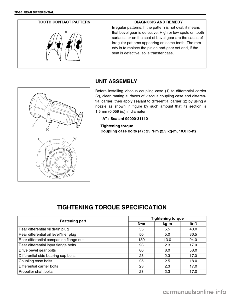
UNIT ASSEMBLY
Before installing viscous coupling case (1) to differential carrier
(2), clean mating surfaces of viscous coupling case and differen-
tial carrier, then apply sealant to differential carrier (2) by using a
nozzle as shown in figure by such amount that its section is
1.5mm (0.059 in.) in diameter.
“A” : Sealant 99000-31110
Tightening torque
Coupling case bolts (a) : 25 N·m (2.5 kg-m, 18.0 lb-ft)
TIGHTENING TORQUE SPECIFICATION
Irregular patterns: If the pattern is not oval, it means
that bevel gear is defective. High or low spots on tooth
surfaces or on the seat of bevel gear are the cause of
irregular patterns appearing on some teeth. The rem-
edy is to replace the pinion and-gear set and, if the
seat is defective, so is transfer case. TOOTH CONTACT PATTERN DIAGNOSIS AND REMEDY
Fastening partTightening torque
Nm kg-m lb-ft
Rear differential oil drain plug 55 5.5 40.0
Rear differential oil level/filler plug 50 5.0 36.5
Rear differential companion flange nut 130 13.0 94.0
Rear differential input flange bolts 23 2.3 17.0
Drive bevel gear bolts 80 8.0 58.0
Differential side bearing cap bolts 23 2.3 17.0
Coupling case bolts 25 2.5 18.0
Differential carrier bolts 23 2.3 17.0
Propeller shaft bolts 23 2.3 17.0
Page 243 of 447
REAR DIFFERENTIAL 7F-21
REQUIRED SERVICE MATERIAL
SPECIAL TOOL
MaterialRecommended SUZUKI product
(Part Number)Use
Thread lock cement THREAD LOCK CEMENT 1322
(99000-32110)Bevel gear bolts
Lithium grease SUZUKI SUPER GREASE A
(99000-25010)Oil seal lips
Sealant SUZUKI BOND NO. 1215
(99000-31110)Thread part of differential carrier bolt
Mating surface of differential housing
Mating surface of rear axle housing
Mating surface of viscous coupling case
09951-16060 09951-76010 09927-28010 09925-88210
Lower arm bush remover Bearing installer Bevel pinion holder Bearing puller attachment
09913-60910 09913-80112 09900-20701 09900-20606
Bearing puller Bearing installer Magnetic stand Dial gauge
09922-76140 09922-76150 09922-76330 09922-76430
Bevel pinion shaft Bevel pinion nut Rear collar Front collar
Page 244 of 447
7F-22 REAR DIFFERENTIAL
09922-76350 09922-76120 09922-76250 09924-74510
Gauge block Dummy shaft Bevel gear dummy Bearing installer handle
09925-68210 09925-98210 09924-84510-002 09930-40113
Bearing installer Bearing installer Bearing installer Flange holder
09913-65135 09913-50121
Bearing puller Oil seal remover
Page 249 of 447

BODY ELECTRICAL SYSTEM 8-5
SPEEDOMETER AND VSS
FUEL METER AND FUEL LEVEL SENSOR (GAUGE UNIT)
ENGINE COOLANT TEMPERATURE (ECT) METER AND ECT SENSOR
OIL PRESSURE WARNING LIGHT
Condition Possible Cause Correction
Speedometer shows
no operation or incor-
rect operation“IG/METER” and/or “RADIO/DOME” fuse(s)
blownReplace fuse(s) to check for short.
VSS faulty Check VSS.
Printed plate in combination meter faulty Check printed plate.
Wiring or grounding faulty Repair circuit.
Signal rotor on differential case faulty Check signal rotor.
Speedometer faulty Replace speedometer.
Condition Possible Cause Correction
Fuel meter shows no
operation or incorrect
operation“IG/METER” fuse blown Replace fuse to check for short.
Fuel gauge unit faulty Check fuel gauge unit.
Printed plate in combination meter faulty Check printed plate.
Fuel meter faulty Check fuel meter.
Wiring or grounding faulty Repair circuit.
Condition Possible Cause Correction
Engine coolant temp.
meter shows no oper-
ation or incorrect
operation“IG/METER” fuse blown Replace fuse to check for short.
ECT meter faulty Check ECT meter.
Printed plate in combination meter faulty Check printed plate.
ECT sensor faulty Check ECT sensor.
Wiring or grounding faulty Repair circuit.
Condition Possible Cause Correction
Oil pressure warning
light does not light up
when turn the ignition
switch to ON position
at engine offBulb in combination meter blown Replace bulb.
“IG/METER” fuse blown Replace fuse to check for short.
Printed plate in combination meter faulty Check printed plate.
Oil pressure switch faulty Check oil pressure switch.
Wiring or grounding faulty Repair circuit.
Oil pressure warning
light stay onOil pressure switch faulty Check oil pressure switch.