Page 15 of 447
![SUZUKI SWIFT 2000 1.G Transmission Service Workshop Manual MANUAL TRANSMISSION 7A-15
[A] : GEAR SHIFTER 12. Reverse gear shift arm 25. Reverse gear shift lever bolt
: Apply thread lock 99000-32110 to all around
thread part of bolt.
[B] : DIFFERENTIAL 13. 5th SUZUKI SWIFT 2000 1.G Transmission Service Workshop Manual MANUAL TRANSMISSION 7A-15
[A] : GEAR SHIFTER 12. Reverse gear shift arm 25. Reverse gear shift lever bolt
: Apply thread lock 99000-32110 to all around
thread part of bolt.
[B] : DIFFERENTIAL 13. 5th](/manual-img/20/7605/w960_7605-14.png)
MANUAL TRANSMISSION 7A-15
[A] : GEAR SHIFTER 12. Reverse gear shift arm 25. Reverse gear shift lever bolt
: Apply thread lock 99000-32110 to all around
thread part of bolt.
[B] : DIFFERENTIAL 13. 5th gear shift fork 26. 5th gear shift fork plug
: Apply thread lock 99000-32110 to all around
thread part of plug.
1. Gear shift & select shaft 14. Side gear washer 27. Guide case
2. 5th & reverse gear shift cam 15. Differential side pinion gear 28. Select lever shaft bush
: Apply grease 99000-25010 to whole area of
bush.
3. Gear shift interlock plate 16. Differential side gear 29. Select lever boss
: Apply grease 99000-25010 to internal and exter-
nal diameter
4. Gear shift & select lever 17. Side gear washer 30. Final gear bolt
: Apply thread lock 99000-32110 to all around
thread part of bolt
5. Shift cable lever 18. Differential side oil seal
: Apply grease 99000- 25010 to oil
seal lip.31. Differential pinion shaft
6. Select cable lever 19. Differential side bearing 32. Differential pinion shaft pin
7. Low speed gear shift shaft 20. Speed sensor ring Tightening torque
8. High speed gear shift shaft 21. Differential case Do not reuse.
9. 5th & reverse gear shift shaft 22. Final gear Apply transmission oil.
10. Reverse gear shift lever 23. 5th to reverse interlock guide bolt
: Apply sealant 99000-31110 to bolt
thread.
11. 5th & reverse gear shift guide
shaft24. Gear shift interlock bolt
: Apply sealant 99000-31110 to bolt
thread.
Page 17 of 447

MANUAL TRANSMISSION 7A-17
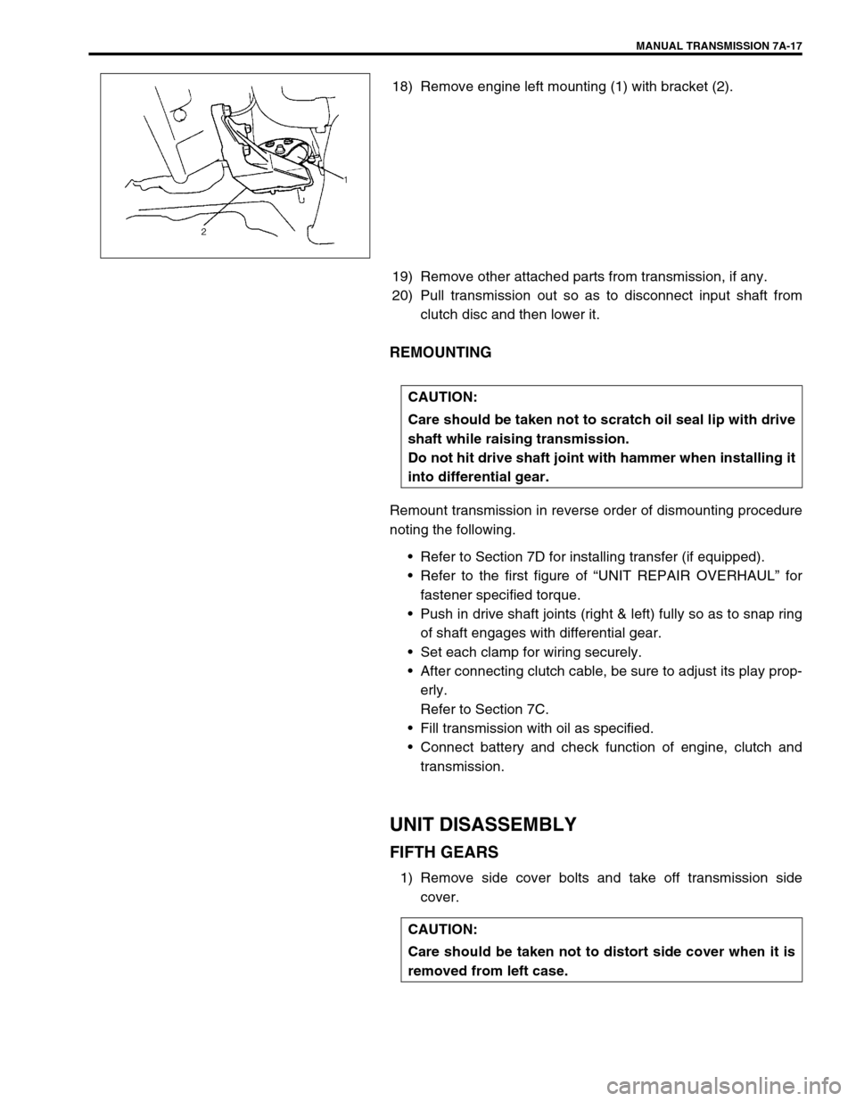
18) Remove engine left mounting (1) with bracket (2).
19) Remove other attached parts from transmission, if any.
20) Pull transmission out so as to disconnect input shaft from
clutch disc and then lower it.
REMOUNTING
Remount transmission in reverse order of dismounting procedure
noting the following.
Refer to Section 7D for installing transfer (if equipped).
Refer to the first figure of “UNIT REPAIR OVERHAUL” for
fastener specified torque.
Push in drive shaft joints (right & left) fully so as to snap ring
of shaft engages with differential gear.
Set each clamp for wiring securely.
After connecting clutch cable, be sure to adjust its play prop-
erly.
Refer to Section 7C.
Fill transmission with oil as specified.
Connect battery and check function of engine, clutch and
transmission.
UNIT DISASSEMBLY
FIFTH GEARS
1) Remove side cover bolts and take off transmission side
cover.
CAUTION:
Care should be taken not to scratch oil seal lip with drive
shaft while raising transmission.
Do not hit drive shaft joint with hammer when installing it
into differential gear.
CAUTION:
Care should be taken not to distort side cover when it is
removed from left case.
Page 20 of 447
7A-20 MANUAL TRANSMISSION
11) Tapping input shaft end with plastic hammer, push it out as
assembly from case a little, then take out input shaft assem-
bly (1), counter shaft assembly (2), high speed gear shift
shaft (3) and low speed gear shift shaft (4) all at once.
12) Remove counter shaft left bearing cup from left case.
13) Remove differential side left oil seal also from left case.
RIGHT CASE
1) Remove differential gear assembly (1) from right case (2).
2) Remove bolt and then pull out VSS (3).
3) If input shaft right bearing has been left in right case, pull it
out by using special tools.
Remove input shaft oil seal (1) by using special tools.
Special tool
(A) : 09930-30104
(B) : 09923-74510
4) Also pull out countershaft right bearing cup (2) by using spe-
cial tools.
Special tool
09941-64511
09923-30104
Page 21 of 447

MANUAL TRANSMISSION 7A-21
SUB ASSEMBLY SERVICE
RIGHT CASE
1) Install input shaft oil seal (1) facing its spring side upward.
Use special tool and hammer for installation and apply
grease to oil seal lip.
“B” : Grease 99000-25010
Special tool
(A) : 09951-76010
2) Install countershaft right bearing cup (2) by using special
tools and hammer.
Special tool
(B) : 09924-74510
(C) : 09925-68210
LEFT CASE
1) If input oil gutter has been removed, install it with bolt to
which thread lock cement have been applied.
“A” : Thread lock cement 99000-32110
Tightening torque
Oil gutter bolt (a) : 10 N·m (1.0 kg-m, 7.5 lb-ft)
2) Install differential side left oil seal (1) facing its spring side
inward until it becomes flush with case surface by using spe-
cial tool with hammer, and then apply grease to its lip.
“B” : Grease 99000-25010
Special tool
(A) : 09913-75510
3) Install counter shaft left bearing cup into case bore by tap-
ping it with plastic hammer lightly. NOTE:
Before installation, wash each part and apply specified
gear oil to sliding faces of bearing and gear.
Page 30 of 447

7A-30 MANUAL TRANSMISSION
2) Insert each gear shift shaft into case and check that it moves
smoothly. If it doesn’t, correct by using oilstone, reamer or
the like.
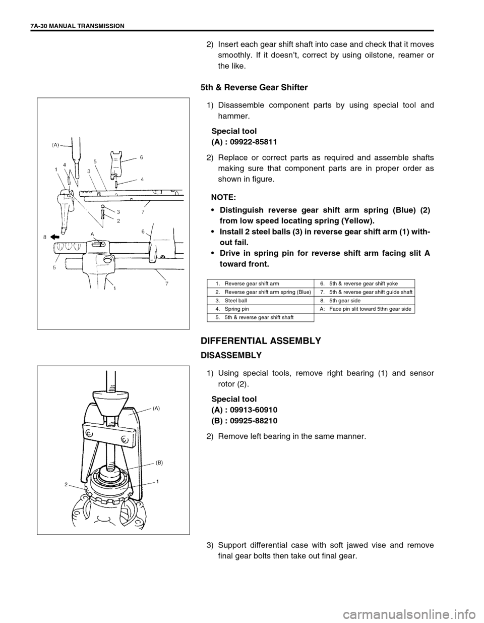
5th & Reverse Gear Shifter
1) Disassemble component parts by using special tool and
hammer.
Special tool
(A) : 09922-85811
2) Replace or correct parts as required and assemble shafts
making sure that component parts are in proper order as
shown in figure.
DIFFERENTIAL ASSEMBLY
DISASSEMBLY
1) Using special tools, remove right bearing (1) and sensor
rotor (2).
Special tool
(A) : 09913-60910
(B) : 09925-88210
2) Remove left bearing in the same manner.
3) Support differential case with soft jawed vise and remove
final gear bolts then take out final gear. NOTE:
Distinguish reverse gear shift arm spring (Blue) (2)
from low speed locating spring (Yellow).
Install 2 steel balls (3) in reverse gear shift arm (1) with-
out fail.
Drive in spring pin for reverse shift arm facing slit A
toward front.
1. Reverse gear shift arm 6. 5th & reverse gear shift yoke
2. Reverse gear shift arm spring (Blue) 7. 5th & reverse gear shift guide shaft
3. Steel ball 8. 5th gear side
4. Spring pin A: Face pin slit toward 5thn gear side
5. 5th & reverse gear shift shaft
Page 31 of 447

MANUAL TRANSMISSION 7A-31
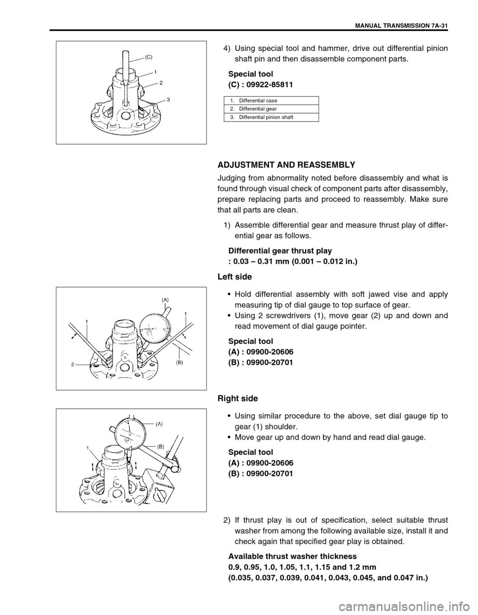
4) Using special tool and hammer, drive out differential pinion
shaft pin and then disassemble component parts.
Special tool
(C) : 09922-85811
ADJUSTMENT AND REASSEMBLY
Judging from abnormality noted before disassembly and what is
found through visual check of component parts after disassembly,
prepare replacing parts and proceed to reassembly. Make sure
that all parts are clean.
1) Assemble differential gear and measure thrust play of differ-
ential gear as follows.
Differential gear thrust play
: 0.03 – 0.31 mm (0.001 – 0.012 in.)
Left side
Hold differential assembly with soft jawed vise and apply
measuring tip of dial gauge to top surface of gear.
Using 2 screwdrivers (1), move gear (2) up and down and
read movement of dial gauge pointer.
Special tool
(A) : 09900-20606
(B) : 09900-20701
Right side
Using similar procedure to the above, set dial gauge tip to
gear (1) shoulder.
Move gear up and down by hand and read dial gauge.
Special tool
(A) : 09900-20606
(B) : 09900-20701
2) If thrust play is out of specification, select suitable thrust
washer from among the following available size, install it and
check again that specified gear play is obtained.
Available thrust washer thickness
0.9, 0.95, 1.0, 1.05, 1.1, 1.15 and 1.2 mm
(0.035, 0.037, 0.039, 0.041, 0.043, 0.045, and 0.047 in.)
1. Differential case
2. Differential gear
3. Differential pinion shaft
Page 32 of 447

7A-32 MANUAL TRANSMISSION
3) Drive in new differential pinion shaft pin (2) till the depth from
differential case (3) surface is about 1 mm (0.04 in.).
4) Press-fit new sensor rotor (1) with groove (4) side downward
as shown by using special tools and copper hammer.
Special tool
(A) : 09913-75510
(B) : 09940-54910
5) Press-fit left bearing by using special tools and copper ham-
mer.
6) Support differential assembly (1) as illustrated so as to left
bearing (2) is floating, and then press-fit right bearing (3) like
left bearing in Step 5).
Special tool
(C) : 09951-76010
(D) : 09951-16060
7) Hold differential assembly with soft jawed vise (3), install final
gear (2) as shown in figure and then tighten bolts (1) with
thread lock cement applied to specified torque.
“A” : Thread lock cement 99000-32110
Tightening torque
Final gear bolts (a) : 90 N·m (9.0 kg-m, 65.0 lb-ft)
NOTE:
Make sure to install final gear in correct installing direc-
tion.
CAUTION:
Use of any other bolts than specified ones is prohibited.
4. Groove
Page 33 of 447

MANUAL TRANSMISSION 7A-33
UNIT ASSEMBLY
DIFFERENTIAL TO LEFT CASE
ASSEMBLY
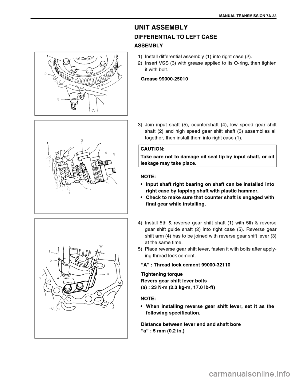
1) Install differential assembly (1) into right case (2).
2) Insert VSS (3) with grease applied to its O-ring, then tighten
it with bolt.
Grease 99000-25010
3) Join input shaft (5), countershaft (4), low speed gear shift
shaft (2) and high speed gear shift shaft (3) assemblies all
together, then install them into right case (1).
4) Install 5th & reverse gear shift shaft (1) with 5th & reverse
gear shift guide shaft (2) into right case (5). Reverse gear
shift arm (4) has to be joined with reverse gear shift lever (3)
at the same time.
5) Place reverse gear shift lever, fasten it with bolts after apply-
ing thread lock cement.
“A” : Thread lock cement 99000-32110
Tightening torque
Revers gear shift lever bolts
(a) : 23 N·m (2.3 kg-m, 17.0 lb-ft)
Distance between lever end and shaft bore
“a” : 5 mm (0.2 in.)
CAUTION:
Take care not to damage oil seal lip by input shaft, or oil
leakage may take place.
NOTE:
Input shaft right bearing on shaft can be installed into
right case by tapping shaft with plastic hammer.
Check to make sure that counter shaft is engaged with
final gear while installing.
NOTE:
When installing reverse gear shift lever, set it as the
following specification.