Page 44 of 447

7B-2 AUTOMATIC TRANSMISSION (4 A/T)
DTC P0702/P1702 (DTC No.52)
TRANSMISSION CONTROL SYSTEM
ELECTRICAL OR INTERNAL
MALFUNCTION OF TCM ....................... 7B-52
INSPECTION OF TCM AND ITS
CIRCUITS ............................................... 7B-53
ON-VEHICLE SERVICE ................................. 7B-55
MAINTENANCE SERVICE ......................... 7B-55
FLUID LEVEL AT NORMAL OPERATING
TEMPERATURE ..................................... 7B-55
FLUID LEVEL AT ROOM
TEMPERATURE ..................................... 7B-56
FLUID CHANGE ..................................... 7B-56
SELECTOR LEVER .................................... 7B-57
TRANSMISSION RANGE SENSOR
(SHIFT SWITCH) ........................................ 7B-58
SELECTOR CABLE .................................... 7B-60
OUTPUT SHAFT SPEED SENSOR
(A/T VSS) .................................................... 7B-62
INPUT SHAFT SPEED SENSOR ............... 7B-63
VEHICLE SPEED SENSOR (VSS)............. 7B-63
THROTTLE POSITION SENSOR............... 7B-63
ENGINE COOLANT TEMP. (ECT)
SENSOR ..................................................... 7B-64
DROPPING RESISTOR ............................. 7B-64
O/D OFF SWITCH ...................................... 7B-65
SHIFT SOLENOID VALVES AND
TRANSMISSION TEMPERATURE
SENSOR ..................................................... 7B-65
SHIFT SOLENOID VALVES ................... 7B-66
TRANSMISSION TEMPERATURE
SENSOR ................................................. 7B-66
DIFFERENTIAL SIDE OIL SEAL ................ 7B-68TRANSMISSION CONTROL MODULE
(TCM).......................................................... 7B-69
LEARNING CONTROL INITIALIZATION 7B-70
BRAKE INTERLOCK SYSTEM
(IF EQUIPPED)........................................... 7B-70
KEY INTERLOCK CABLE
(IF EQUIPPED)........................................... 7B-72
TRANSMISSION UNIT REPAIR
OVERHAUL ................................................... 7B-75
DISMOUNTING .......................................... 7B-76
REMOUNTING ........................................... 7B-77
UNIT DISASSEMBLY ................................. 7B-78
DISASSEMBLY/ASSEMBLY OF
SUBASSEMBLY ......................................... 7B-88
OIL PUMP ............................................... 7B-88
FRONT CLUTCH (C2 CLUTCH) ............ 7B-91
REAR CLUTCH (C1 CLUTCH) ............... 7B-95
DIRECT CLUTCH (C0 CLUTCH) ......... 7B-100
PLANETARY SET................................. 7B-104
VALVE BODY ....................................... 7B-106
DIFFERENTIAL ASSEMBLY ................ 7B-112
REAR COVER (O/D BRAKE PISTON
ASSEMBLY) ......................................... 7B-115
PLANETARY SUN GEAR NO.1
ASSEMBLY .......................................... 7B-115
TORQUE CONVERTER HOUSING ..... 7B-116
TRANSMISSION CASE ........................ 7B-117
UNIT ASSEMBLY ..................................... 7B-118
TIGHTENING TORQUE SPECIFICATION .. 7B-136
SPECIAL TOOL ........................................... 7B-137
REQUIRED SERVICE MATERIAL .............. 7B-139
Page 45 of 447

AUTOMATIC TRANSMISSION (4 A/T) 7B-3
GENERAL DESCRIPTION
This automatic transmission is a full automatic type with 3-speed plus overdrive (O/D).
The torque converter is a 3-element, 1-step and 2-phase type equipped with lock-up mechanism. The gear shift
device consists of 2 sets of planetary gear units, sets of 3 disc type clutches, 3sets of disc type brakes and one-
way clutch. The gear shift is done by selecting one of 6 positions (“P”, “R”, “N”, “D”, “2” and “L”) by means of the
select lever installed on the floor. On the shift knob, there is an overdrive (O/D) cut switch which allows shift-up
to the overdrive mode and shift-down from the overdrive mode.
1. Final gear 6. Overdrive brake (B0) 11. Oil strainer 16. Front clutch (C2)
2. Differential gear assembly 7. Direct clutch (C0) 12. Counter drive gear (Reduction gear) 17. Reverse brake (B2)
3. Parking gear 8. Rear planetary gear 13. Oil pump 18. Rear clutch (C1)
4. Counter driven gear (Reduction gear) 9. Front planetary gear 14. Input shaft 19. Differential drive pinion shaft
5. 1st and 2nd brake (B1) 10. Valve body assembly 15. Torque converter
Page 46 of 447

7B-4 AUTOMATIC TRANSMISSION (4 A/T)
Item Specifications
Torque
converterType
Stall torque ratio3-element, 1-step, 2-phase type
1.65 –1.85
Oil pumpType
Drive systemInternal gear type oil pump
Engine driven
Gear
change
deviceType Forward 4-step, reverse 1-step planetary gear type
Shift position“P” range Gear in neutral, output shaft fixed, engine start
“R” range Reverse
“N” range Gear in neutral, engine start
“D” range
(O/D ON)Forward 1st ↔
2nd ↔
3rd ↔
4th (O/D)
automatic gear change
“D” range
(O/D OFF)Forward 1st ↔
2nd ↔
3rd ←
4th
automatic gear change
“2” range Forward 1st ↔
2nd ←
3rd automatic gear change
“L” range Forward 1st ←
2nd reduction, and fixed at 1st gear
Gear
ratio1st 2.962
2nd 1.515 Number of teeth Front sun gear : 34
Rear sun gear : 21
Front pinion gear : 16
Rear pinion gear : 19
Front internal gear : 66
Rear internal gear : 59 3rd 1.000
4th
(overdrive gear)0.737
Reverse
(reverse gear2.809
Control elementsWet type multi-disc clutch ... 3 sets
One-way clutch ... 1 set
Wet type multi-disc brake ... 3 sets
Reduction gear ratio 1.209
Final gear ratio
(Differential)3.578 (for 2WD vehicle), 3.894 (for 4WD vehicle)
Lubrication Lubrication system Force feed system by oil pump
Cooling Cooling system Water-cooled
Fluid used
Equivalent of DEXRON
-III or DEXRON-IIE
Page 110 of 447
7B-68 AUTOMATIC TRANSMISSION (4 A/T)
DIFFERENTIAL SIDE OIL SEAL
REPLACEMENT
1) Lift up vehicle and drain transmission oil.
2) Remove drive shaft joints from differential gear of transmis-
sion.
Refer to Section 4 for procedure to disconnect drive shaft
joints.
For differential side oil seal removal, it is not necessary to
remove drive shafts from steering knuckle.
For 4WD vehicle, remove transfer referring to Section 7D.
3) Remove differential side oil seal (1) by using flat end rod or
like.
4) Install new differential side oil seal by using special tool.
Special tool
(A) : 09940-53111
(B) : 09913-75510
5) Install drive shaft referring to Section 4.
6) Refill A/T fluid referring to “FLUID CHANGE” in this section. NOTE:
For oil seal installation, press-fit oil seal so that transmis-
sion case end face is flush with oil seal end face.
2. Steering gear box
3. A/T oil pan
4. Torque converter hous-
ing
5. Transmission case
Page 123 of 447
AUTOMATIC TRANSMISSION (4 A/T) 7B-81
17) Remove thrust needle roller bearing (1) and thrust bearing
race (2) from the top of counter driven gear assembly (3).
18) Remove differential gear assembly (1).
19) Remove oil pump assembly and gasket (1).
20) Remove front clutch assembly (1).
21) Remove thrust bearing race (1) and thrust needle roller bear-
ing (2).
Page 154 of 447
7B-112 AUTOMATIC TRANSMISSION (4 A/T)
DIFFERENTIAL ASSEMBLY
Servicing procedure for differential assembly is similar to that for manual transmission. Refer to Section 7A of
this manual for adjustment procedure.
DISASSEMBLY
1) Remove R bearing and then speed sensor rotor using spe-
cial tool and puller.
Special tool
(A) : 09925-88210
2) Hold differential assembly with soft jawed vise, remove final
gear (1).
1. Differential pinion 7. Differential right side bearing (R bearing) 13. Pinion shaft pin
2. Differential gear
8. Speedometer sensor rotor Apply automatic transmission fluid.
3. Washer (for pinion)
9. Differential case Tightening torque
4. Pinion shaft
10. Final gear Do not reuse.
5. Washer (for gear) 11. Bolt
6. Differential side oil seal
: Apply grease 99000-25030 to oil seal lip.
12. Differential left side bearing (L bearing)
1. Differential gear assembly
Page 155 of 447

AUTOMATIC TRANSMISSION (4 A/T) 7B-113
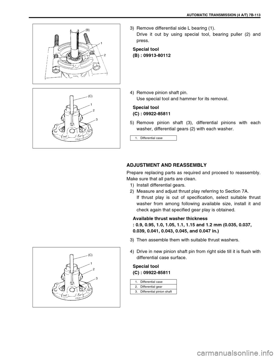
3) Remove differential side L bearing (1).
Drive it out by using special tool, bearing puller (2) and
press.
Special tool
(B) : 09913-80112
4) Remove pinion shaft pin.
Use special tool and hammer for its removal.
Special tool
(C) : 09922-85811
5) Remove pinion shaft (3), differential pinions with each
washer, differential gears (2) with each washer.
ADJUSTMENT AND REASSEMBLY
Prepare replacing parts as required and proceed to reassembly.
Make sure that all parts are clean.
1) Install differential gears.
2) Measure and adjust thrust play referring to Section 7A.
If thrust play is out of specification, select suitable thrust
washer from among following available size, install it and
check again that specified gear play is obtained.
Available thrust washer thickness
: 0.9, 0.95, 1.0, 1.05, 1.1, 1.15 and 1.2 mm (0.035, 0.037,
0.039, 0.041, 0.043, 0.045, and 0.047 in.)
3) Then assemble them with suitable thrust washers.
4) Drive in new pinion shaft pin from right side till it is flush with
differential case surface.
Special tool
(C) : 09922-85811
1. Differential case
1. Differential case
2. Differential gear
3. Differential pinion shaft
Page 156 of 447

7B-114 AUTOMATIC TRANSMISSION (4 A/T)
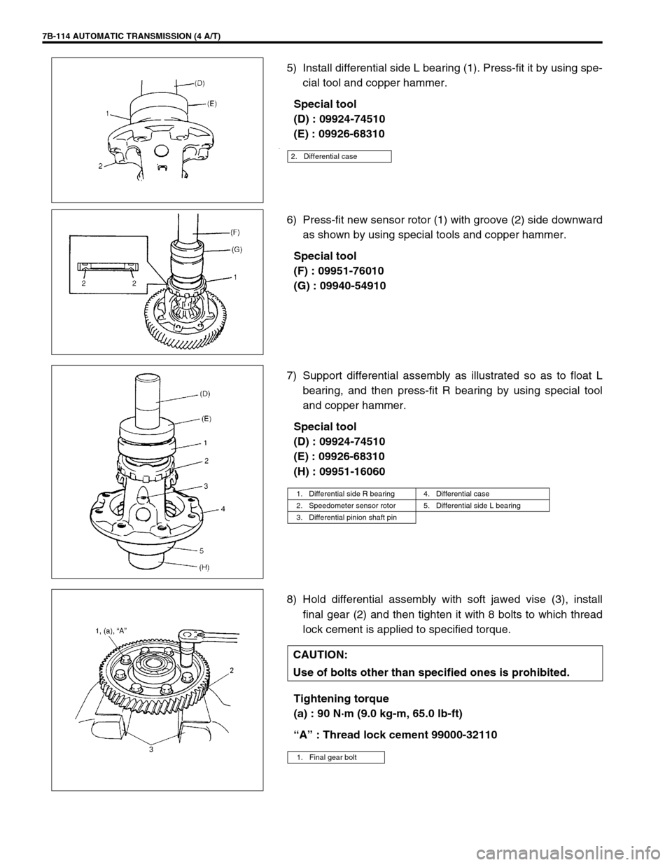
5) Install differential side L bearing (1). Press-fit it by using spe-
cial tool and copper hammer.
Special tool
(D) : 09924-74510
(E) : 09926-68310
.
6) Press-fit new sensor rotor (1) with groove (2) side downward
as shown by using special tools and copper hammer.
Special tool
(F) : 09951-76010
(G) : 09940-54910
7) Support differential assembly as illustrated so as to float L
bearing, and then press-fit R bearing by using special tool
and copper hammer.
Special tool
(D) : 09924-74510
(E) : 09926-68310
(H) : 09951-16060
8) Hold differential assembly with soft jawed vise (3), install
final gear (2) and then tighten it with 8 bolts to which thread
lock cement is applied to specified torque.
Tightening torque
(a) : 90 N·m (9.0 kg-m, 65.0 lb-ft)
“A” : Thread lock cement 99000-32110
2. Differential case
1. Differential side R bearing 4. Differential case
2. Speedometer sensor rotor 5. Differential side L bearing
3. Differential pinion shaft pin
CAUTION:
Use of bolts other than specified ones is prohibited.
1. Final gear bolt