2000 SUZUKI SWIFT battery
[x] Cancel search: batteryPage 268 of 447

8-24 BODY ELECTRICAL SYSTEM
Automatic Stop Operation
1) Connect battery positive terminal to terminal “L” and its neg-
ative terminal to motor bracket (wiper ground) and let the
motor turn.
2) Disconnect terminal “L” from battery positive terminal, and
let the motor stop.
3) Connect terminal “L” and “S” with a jumper wire, and connect
terminal “B” to battery positive terminal. Observe the motor
turns once again then stops at a specified position.
4) Repeat Step 1) to 3) several times and check that the motor
stops at the specified position every time.
If check result is not satisfied, replace.
WASHER TANK AND WASHER PUMP
REMOVAL
1) Disconnect negative cable at battery.
2) Remove front fender lining (RH).
3) Remove washer tank attaching nuts and inlet pipe (4).
4) Disconnect pump lead wire coupler(s) and hoses.
5) Remove washer tank (1).
6) Remove front washer pump (2) and rear washer pump (3) (if
equipped) from washer tank (1).
INSTALLATION
Reverse removal procedure for installation.
INSPECTION
1) Connect battery (+) and (-) terminals to pump (+) and (-) ter-
minals respectively.
2) Check motor operation for both front and rear (if equipped)
washer pump.
LH
S
B
Page 269 of 447

BODY ELECTRICAL SYSTEM 8-25
REAR WIPER AND WASHER SWITCH (IF EQUIPPED)
INSPECTION
Check for continuity between terminals at each switch position as
shown below.
If check result is not as specified, replace.
REAR WIPER MOTOR
INSPECTION
Wiper Motor
Use a 12 V battery to connect its (+) and (-) terminals to terminal
“L” and terminal “E” respectively. Then motor should rotate at 35
to 45 rpm.
Automatic Stop Operation
1) Connect battery positive terminal to terminal “L” and its neg-
ative terminal to terminal “E” and let the motor turn.
2) Disconnect terminal “L” from battery positive terminal and let
the motor stop.
3) Connect terminal “B” to battery positive terminal. Observe
the motor turns once again then stops at a specified position.
4) Repeat Step 1) to 3) several times, and check that the motor
stops at the specified position every time.
IGNITION KEY REMAINDER (IF EQUIPPED)
AND LIGHT REMAINDER WARNING BUZZER
REMOVAL
1) Remove combination meter. Refer to “COMBINATION
METER”.
2) Remove buzzer unit (1) from combination meter.
INSTALLATION
Reverse removal procedure for installation.
Terminal
Position
(1) WIPER and WASHER ON
(2) WIPER ON
(3) OFFIG LO WA
(4) WASHER and WASHER ON
B
E L
Page 273 of 447

BODY ELECTRICAL SYSTEM 8-29
DOOR LOCK ACTUATOR
ON-VEHICLE INSPECTION
1) Remove door trim (front, rear or back) and disconnect door
lock actuator (3) coupler.
2) Connect battery (+) terminal to terminal “L” and (-) terminal
to terminal “UL”. Check that door lock actuator (3) is on
“LOCK” position.
If check result is not satisfied, replace.
3) Connect battery (+) terminal to terminal “UL” and (-) terminal
to terminal “L”. Check that door lock actuator (3) is on
“UNLOCK” position.
If check result is not satisfied, replace.
KEYLESS ENTRY SYSTEM (IF EQUIPPED)
DOOR LOCK CONTROLLER
INSPECTION
Refer to DOOR LOCK CONTROLLER of POWER DOOR LOCK
SYSTEM (IF EQUIPPED) in this section.
DOOR LOCK ACTUATOR
INSPECTION
Refer to DOOR LOCK ACTUATOR of POWER DOOR LOCK
SYSTEM (IF EQUIPPED) in this section.
[A] : FRONT DOOR
[B] : REAR DOOR
[C] : BACK DOOR
Page 274 of 447

8-30 BODY ELECTRICAL SYSTEM
RECEIVER
INSPECTION
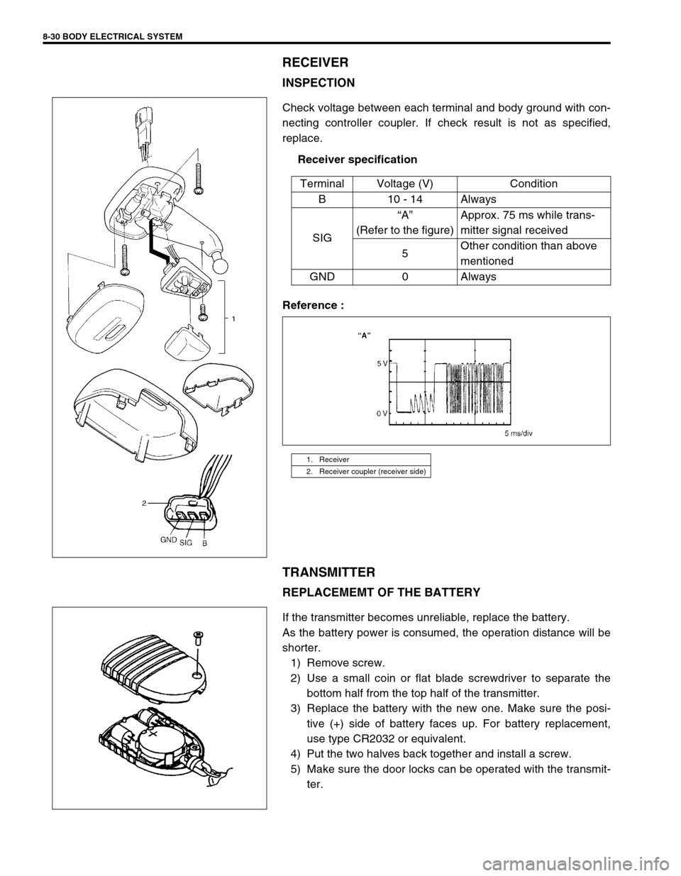
Check voltage between each terminal and body ground with con-
necting controller coupler. If check result is not as specified,
replace.
Receiver specification
Reference :
TRANSMITTER
REPLACEMEMT OF THE BATTERY
If the transmitter becomes unreliable, replace the battery.
As the battery power is consumed, the operation distance will be
shorter.
1) Remove screw.
2) Use a small coin or flat blade screwdriver to separate the
bottom half from the top half of the transmitter.
3) Replace the battery with the new one. Make sure the posi-
tive (+) side of battery faces up. For battery replacement,
use type CR2032 or equivalent.
4) Put the two halves back together and install a screw.
5) Make sure the door locks can be operated with the transmit-
ter. Terminal Voltage (V) Condition
B10 - 14Always
SIG“A”
(Refer to the figure)Approx. 75 ms while trans-
mitter signal received
5Other condition than above
mentioned
GND 0 Always
1. Receiver
2. Receiver coupler (receiver side)
Page 275 of 447

BODY ELECTRICAL SYSTEM 8-31
CODE REGISTRATION PROCEDURE
1) Confirm that IG switch is OFF position.
2) Remove DOOR LOCK fuse and install it again.
3) Press the button on the transmitter one time toward the
receiver within 30 seconds.
4) If two transmitters are registered, repeat step 1) to 3) with
other transmitter.
POWER DOOR MIRROR CONTROL SYSTEM
(IF EQUIPPED)
MIRROR SWITCH
INSPECTION
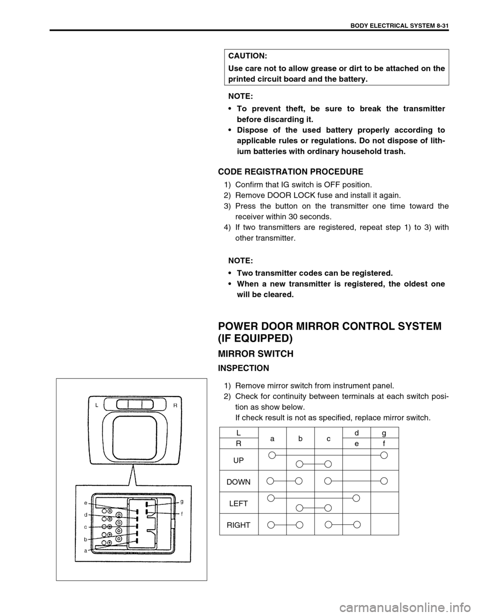
1) Remove mirror switch from instrument panel.
2) Check for continuity between terminals at each switch posi-
tion as show below.
If check result is not as specified, replace mirror switch. CAUTION:
Use care not to allow grease or dirt to be attached on the
printed circuit board and the battery.
NOTE:
To prevent theft, be sure to break the transmitter
before discarding it.
Dispose of the used battery properly according to
applicable rules or regulations. Do not dispose of lith-
ium batteries with ordinary household trash.
NOTE:
Two transmitter codes can be registered.
When a new transmitter is registered, the oldest one
will be cleared.
UP
DOWN
LEFT
RIGHTL
Rabcd
eg
f
Page 276 of 447

8-32 BODY ELECTRICAL SYSTEM
DOOR MIRROR ACTUATOR
INSPECTION
1) Remove garnish from door.
2) Pull out door mirror coupler at bracket.
3) Disconnect door mirror coupler.
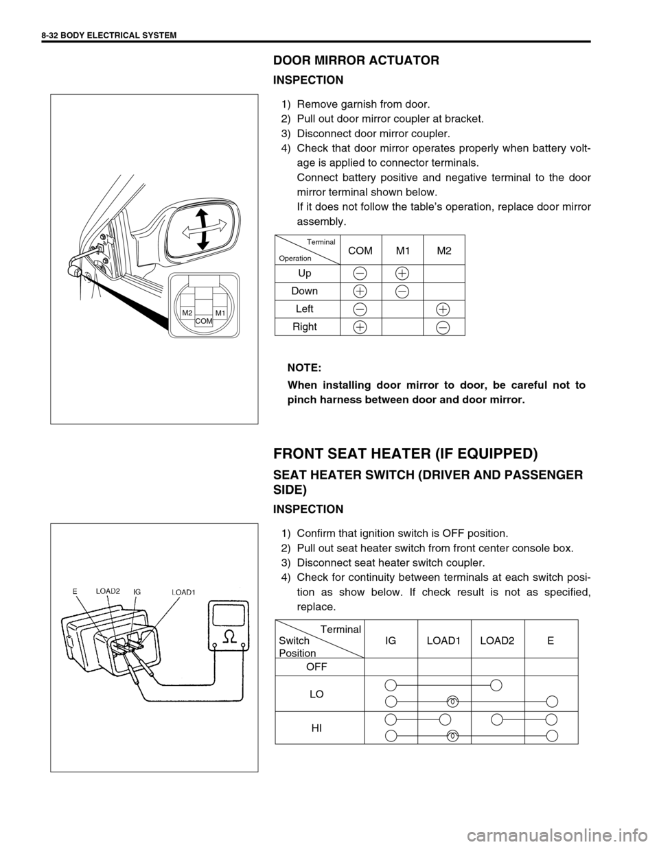
4) Check that door mirror operates properly when battery volt-
age is applied to connector terminals.
Connect battery positive and negative terminal to the door
mirror terminal shown below.
If it does not follow the table’s operation, replace door mirror
assembly.
FRONT SEAT HEATER (IF EQUIPPED)
SEAT HEATER SWITCH (DRIVER AND PASSENGER
SIDE)
INSPECTION
1) Confirm that ignition switch is OFF position.
2) Pull out seat heater switch from front center console box.
3) Disconnect seat heater switch coupler.
4) Check for continuity between terminals at each switch posi-
tion as show below. If check result is not as specified,
replace. NOTE:
When installing door mirror to door, be careful not to
pinch harness between door and door mirror.
M2COMM1
Terminal
Operation
UpCOM M1 M2
Down
Left
Right
Terminal
Switch
Position
OFF
LO
HIIG LOAD1 LOAD2 E
Page 279 of 447

IMMOBILIZER CONTROL SYSTEM 8G-1
6F1
6F2
6G
6H
6K
7A
7A1
7B1
7C1
7D
7E
7F
8A
8B
8C
8D
8G
9
10
10A
10B
SECTION 8G
IMMOBILIZER CONTROL SYSTEM
CONTENTS
GENERAL DESCRIPTION ............................. 8G-2
WIRING CIRCUIT ....................................... 8G-3
ON-BOARD DIAGNOSTIC SYSTEM
(SELF-DIAGNOSIS FUNCTION) ................ 8G-4
DIAGNOSIS .................................................... 8G-5
PRECAUTIONS IN DIAGNOSING
TROUBLES ................................................. 8G-5
PRECAUTIONS IN IDENTIFYING
DIAGNOSTIC TROUBLE CODE............. 8G-5
DIAGNOSTIC FLOW TABLE ...................... 8G-6
DIAGNOSTIC TROUBLE CODE (DTC)
CHECK
(IMMOBILIZER CONTROL MODULE)........ 8G-7
DIAGNOSTIC TROUBLE CODE (DTC)
CHECK (ECM) ............................................ 8G-8
DIAGNOSTIC TROUBLE CODE TABLE .... 8G-9
TABLE A - IMMOBILIZER INDICATOR
LAMP CHECK (IMMOBILIZER INDICATOR
LAMP DOES NOT LIGHT AT IGNITION
SWITCH ON) ............................................ 8G-10
TABLE B - IMMOBILIZER INDICATOR
LAMP CHECK (IMMOBILIZER INDICATOR
LAMP REMAINS ON AFTER ENGINE
STARTS) ................................................... 8G-11
TABLE C - DTC IS NOT OUTPUT FROM
IMMOBILIZER CONTROL MODULE ........ 8G-12
DTC11/32 TRANSPONDER CODE NOT
MATCHED ................................................ 8G-13
DTC31 TRANSPONDER CODE NOT
REGISTERED ........................................... 8G-14
DTC12 FAULT IN IMMOBILIZER
CONTROL MODULE ................................ 8G-14DTC13 NO TRANSPONDER CODE
TRANSMITTED OR COIL ANTENNA
OPENED/SHORTED ................................. 8G-15
DTC21 ECM/IMMOBILIZER CONTROL
MODULE CODE NOT MATCHED
(IMMOBILIZER CONTROL MODULE
SIDE) ......................................................... 8G-16
DTC P1623 ECM/IMMOBILIZER CONTROL
MODULE CODE NOT MATCHED (ECM
SIDE) ......................................................... 8G-16
DTC P1620 ECM/IMMOBILIZER CONTROL
MODULE CODE NOT REGISTERED ....... 8G-16
DTC P1622 FAULT IN ECM ...................... 8G-16
DTC22 IGNITION SWITCH CIRCUIT
OPEN/SHORT ........................................... 8G-17
DTC23 NO ECM/IMMOBILIZER CONTROL
MODULE CODE TRANSMITTED FROM
ECM OR DLC CIRCUIT OPENED/
SHORTED ................................................. 8G-18
DTC P1621 NO ECM/IMMOBILIZER
CONTROL MODULE CODE TRANSMITTED
FROM IMMOBILIZER CONTROL
MODULE OR DLC CIRCUIT OPENED/
SHORTED ................................................. 8G-18
INSPECTION OF ECM, IMMOBILIZER
CONTROL MODULE AND ITS CIRCUIT .. 8G-20
ON-VEHICLE SERVICE ................................ 8G-21
PRECAUTIONS IN HANDLING
IMMOBILIZER CONTROL SYSTEM ......... 8G-21
IMMOBILIZER CONTROL MODULE ......... 8G-22
HOW TO REGISTER IGNITION KEY ........... 8G-23 WARNING:
For vehicles equipped with Supplemental Restraint (Air Bag) System
Service on and around the air bag system components or wiring must be performed only by an
authorized SUZUKI dealer. Refer to “Air Bag System Components and Wiring Location View” under
“General Description” in air bag system section in order to confirm whether you are performing ser-
vice on or near the air bag system components or wiring. Please observe all WARNINGS and “Ser-
vice Precautions” under “On-Vehicle Service” in air bag system section before performing service
on or around the air bag system components or wiring. Failure to follow WARNINGS could result in
unintentional activation of the system or could render the system inoperative. Either of these two
conditions may result in severe injury.
Technical service work must be started at least 90 seconds after the ignition switch is turned to the
“LOCK” position and the negative cable is disconnected from the battery. Otherwise, the system
may be activated by reserve energy in the Sensing and Diagnostic Module (SDM).
Page 283 of 447

IMMOBILIZER CONTROL SYSTEM 8G-5
DIAGNOSIS
PRECAUTIONS IN DIAGNOSING TROUBLES
PRECAUTIONS IN IDENTIFYING DIAGNOSTIC TROUBLE CODE
ECM
Before identifying diagnostic trouble code indicated through Suzuki scan tool, don't disconnect couplers from
ECM, battery cable from battery, ECM ground wire harness from engine.
Such disconnection will clear trouble codes for engine and emission control system and immobilizer control
system stored in memory of ECM.
Take a note of diagnostic trouble code indicated first.
IMMOBILIZER CONTROL MODULE
Take a note of diagnostic trouble code indicated first.
INTERMITTENT TROUBLES
There is case where Suzuki scan tool indicate a diagnostic trouble code representing a trouble which
occurred only temporarily and has gone. In such case, it may occur that good parts are replaced unneces-
sarily. To prevent such accident, be sure to follow instructions given below when checking by using “Diag-
nostic Flow Table”.
–When trouble can be identified, it is not an intermittent one :
Check coil antenna, ignition key, wires and each connection and if they are all in good condition, substi-
tute a known-good ECM and recheck.
–When trouble can not be identified but Suzuki scan tool indicate a trouble code :
Diagnose trouble by using that code No. and if ignition key, coil antenna, wires and each connection are
all in good condition, turn OFF ignition switch and then ON.
Then check what Suzuki scan tool indicate.Only when they indicate trouble code again, substitute a known-
good ECM or Immobilizer Control Module and check again.
If they indicate not trouble code but normal code, it means that an intermittent trouble did occur and has gone. In
this case, check wires and connections carefully again.