Page 66 of 447

7B-24 AUTOMATIC TRANSMISSION (4 A/T)
ELECTRONIC CONTROL SYSTEM DIAGNO-
SIS
TCM has on-board diagnostic system (a system self-diagnosis
function). Investigate where the trouble is by referring to “DIAG-
NOSTIC FLOW TABLE” and “DTC TABLE” in this section.
PRECAUTIONS IN DIAGNOSING TROUBLES
[PRECAUTIONS IN IDENTIFYING DTC]
For vehicle equipped with immobilizer indicator lamp (2)
(which comes on when turning on ignition switch leaving
engine OFF), malfunction indicator lamp (MIL) (1) comes on
when TCM detects malfunction of automatic transmission
system.
For vehicle equipped without immobilizer indicator lamp (2),
malfunction indicator lamp (MIL) (1) does not come on
although TCM detects malfunction of automatic transmission
system.
Don’t disconnect couplers from TCM, battery cable from bat-
tery, TCM ground wire harness from engine or main fuse
before checking DTC stored in TCM memory.
Such disconnection will clear memorized information in TCM
memory.
Using SUZUKI scan tool (Tech-1) (4), diagnostic trouble
code (DTC) stored in TCM memory can be checked and
cleared as well.
Before its use, be sure to read Operator’s (instruction) Man-
ual supplied with it carefully to have good understanding of
its functions and usage.
Not using scan tool, the DTC stored in TCM memory also
can be checked and cleared.
DTC stored in the TCM memory is outputted by flashing of
“O/D OFF” lamp (3) with diagnosis switch terminal of monitor
connector No.2 (5) grounded.
If no DTC is stored in TCM memory, DTC No.12 is outputted
repeatedly.
If one or more DTCs are stored in TCM memory, they are
outputted starting from smallest code number in increasing
order.
After all DTCs are outputted, all DTCs are outputted repeat-
edly.
Be sure to read “PRECAUTIONS FOR ELECTRICAL CIR-
CUIT SERVICE” in Section 0A before inspection and
observe what is written there.
When replacing TCM with used one, all learned contents
which are stored in TCM memory should be erased after the
replacement referring to “LEARNING CONTROL INITIAL-
IZATION” in this section.
Page 72 of 447
7B-30 AUTOMATIC TRANSMISSION (4 A/T)
TCM POWER AND GROUND CIRCUIT CHECK
1. Battery 4. Circuit fuse (IG) 7. TCM
2. Main fuse 5. Ground
3. Ignition switch 6. A/T relay
DTC DETECTING CONDITION
Automatic transmission doesn’t shift to 1st gear at vehicle start in “D” range.
Step Action Yes No
1 Check voltage between terminal “C44-2” of
TCM coupler and body ground with ignition
switch ON.
Is it 10 – 14 V?Go to Step 2. YEL/BLK wire open or
faulty
A/T relay.
2 Check voltage between terminal “C44-15” of
TCM coupler and body ground with ignition
switch ON.
Is it about 0 V?Poor “C44-2” or “C44-15”
connection.
If all above are OK,
replace known-good TCM
and recheck.“BLK” wire open.
Page 95 of 447

AUTOMATIC TRANSMISSION (4 A/T) 7B-53
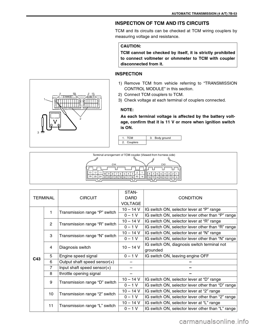
INSPECTION OF TCM AND ITS CIRCUITS
TCM and its circuits can be checked at TCM wiring couplers by
measuring voltage and resistance.
INSPECTION
1) Remove TCM from vehicle referring to “TRANSMISSION
CONTROL MODULE” in this section.
2) Connect TCM couplers to TCM.
3) Check voltage at each terminal of couplers connected.CAUTION:
TCM cannot be checked by itself, it is strictly prohibited
to connect voltmeter or ohmmeter to TCM with coupler
disconnected from it.
NOTE:
As each terminal voltage is affected by the battery volt-
age, confirm that it is 11 V or more when ignition switch
is ON.
1. TCM 3. Body ground
2. Couplers
TERMINAL CIRCUITSTAN-
DARD
VOLTAGECONDITION
C431 Transmission range “P” switch10 – 14 V IG switch ON, selector lever at “P” range
0 – 1 V IG switch ON, selector lever other than “P” range
2 Transmission range “R” switch10 – 14 V IG switch ON, selector lever at “R” range
0 – 1 V IG switch ON, selector lever other than “R” range
3 Transmission range “N” switch10 – 14 V IG switch ON, selector lever at “N” range
0 – 1 V IG switch ON, selector lever other than “N” range
4 Diagnosis switch 10 – 14 VIG switch ON, diagnosis switch terminal not
grounded
5 Engine speed signal 0 – 1 V IG switch ON, leaving engine OFF
6 Output shaft speed sensor(+)––
7 Input shaft speed sensor(+)––
8 throttle opening signal––
9 Transmission range “D” switch10 – 14 V IG switch ON, selector lever at “D” range
0 – 1 V IG switch ON, selector lever other than “D” range
10 Transmission range “2” switch10 – 14 V IG switch ON, selector lever at “2” range
0 – 1 V IG switch ON, selector lever other than “2” range
11 Transmission range “L” switch10 – 14 V IG switch ON, selector lever at “L” range
0 – 1 V IG switch ON, selector lever other than “L” range
Page 104 of 447
7B-62 AUTOMATIC TRANSMISSION (4 A/T)
OUTPUT SHAFT SPEED SENSOR (A/T VSS)
INSPECTION
1) Disconnect negative cable at battery.
2) Disconnect output shaft speed sensor – input shaft speed
sensor coupler (1).
3) Check resistance between output shaft speed sensor termi-
nals (2).
Output shaft speed sensor resistance
Standard : 160 – 200
Ω
ΩΩ Ω at 20°C (68°F)
REMOVAL
1) Disconnect negative cable at battery.
2) Disconnect output shaft speed sensor – input shaft speed
sensor coupler.
3) Remove output shaft speed sensor (1) by removing its bolt.
INSTALLATION
1) Apply A/T fluid to output shaft speed sensor o-ring.
2) Install output shaft speed sensor (1) to A/T case and tighten
bolt to specified torque.
Tightening torque
Output shaft speed sensor bolt
(a) : 8 N·m (0.8 kg-m, 6.0 lb-ft)
3) Connect output shaft speed sensor – input shaft speed sen-
sor coupler.
4) Connect negative cable to battery.
Page 105 of 447

AUTOMATIC TRANSMISSION (4 A/T) 7B-63
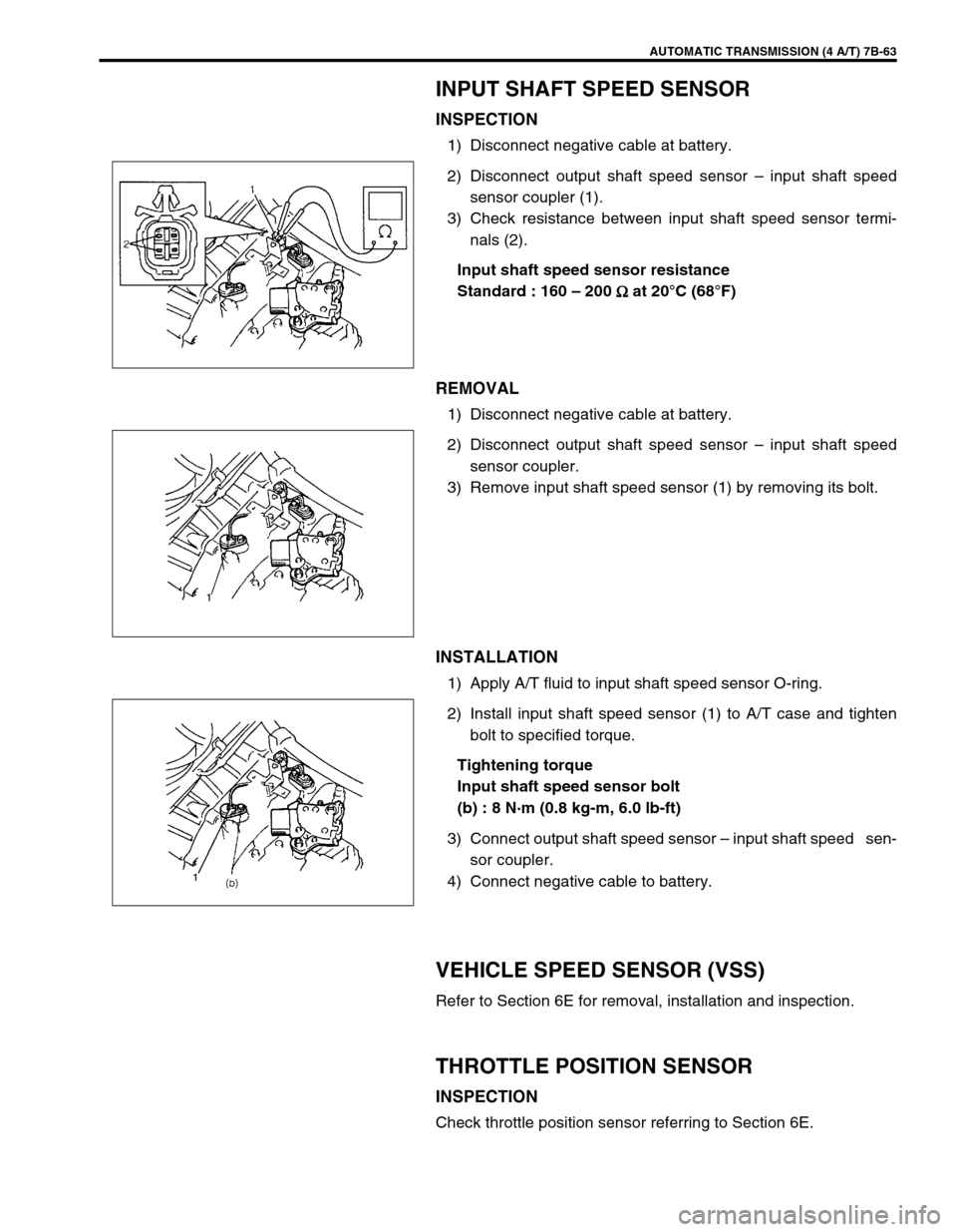
INPUT SHAFT SPEED SENSOR
INSPECTION
1) Disconnect negative cable at battery.
2) Disconnect output shaft speed sensor – input shaft speed
sensor coupler (1).
3) Check resistance between input shaft speed sensor termi-
nals (2).
Input shaft speed sensor resistance
Standard : 160 – 200
Ω
ΩΩ Ω at 20°C (68°F)
REMOVAL
1) Disconnect negative cable at battery.
2) Disconnect output shaft speed sensor – input shaft speed
sensor coupler.
3) Remove input shaft speed sensor (1) by removing its bolt.
INSTALLATION
1) Apply A/T fluid to input shaft speed sensor O-ring.
2) Install input shaft speed sensor (1) to A/T case and tighten
bolt to specified torque.
Tightening torque
Input shaft speed sensor bolt
(b) : 8 N·m (0.8 kg-m, 6.0 lb-ft)
3) Connect output shaft speed sensor – input shaft speed sen-
sor coupler.
4) Connect negative cable to battery.
VEHICLE SPEED SENSOR (VSS)
Refer to Section 6E for removal, installation and inspection.
THROTTLE POSITION SENSOR
INSPECTION
Check throttle position sensor referring to Section 6E.
Page 107 of 447
AUTOMATIC TRANSMISSION (4 A/T) 7B-65
O/D OFF SWITCH
INSPECTION
1) Remove console box.
2) Disconnect O/D off switch coupler (1).
3) Check continuity between O/D off switch terminals.
O/D OFF switch specification
SHIFT SOLENOID VALVES AND TRANSMIS-
SION TEMPERATURE SENSOR
REMOVAL
1) Disconnect negative cable at battery.
2) Drain A/T fluid.
3) Remove A/T oil pan (1).
4) Disconnect transmission temp. sensor coupler (3).
5) Remove A/T oil strainer (2) and transmission temp. sensor
(1). O/D off switch ON OFF
Continuity Continuity No continuity
2. O/D off switch ON
3. O/D off switch OFF
Page 108 of 447
7B-66 AUTOMATIC TRANSMISSION (4 A/T)
6) Disconnect shift solenoid couplers.
7) Remove shift solenoid valves.
SHIFT SOLENOID VALVES
INSPECTION
Resistance Check
Shift solenoid A (No.1), B (No.2) and lock-up solenoid
Resistance between terminal and solenoid body
Standard : 10.5 – 15.5
Ω
ΩΩ Ω
Shift solenoid C (No.3), D (No.4) or E (No.5)
Resistance between terminal and solenoid body
Standard : 2.5 – 3.5
Ω
ΩΩ Ω
Operation check
When solenoids is connected to the battery as shown in figure,
check that the solenoid actuates with a click sound.
TRANSMISSION TEMPERATURE SENSOR
INSPECTION
Warm up transmission temp. sensor. Thus make sure its resis-
tance decrease with the increase of temperature.
Transmission temperature sensor resistance
1. Solenoid valve
1. Solenoid valve
Temperature Resistance
20°C (68°F) 2.5 k
Ω
ΩΩ Ω
40°C (104°F) 1.2 k
Ω
ΩΩ Ω
60°C (140°F) 0.6 k
Ω
ΩΩ Ω
1. Transmission temperature sensor coupler
Page 111 of 447
AUTOMATIC TRANSMISSION (4 A/T) 7B-69
TRANSMISSION CONTROL MODULE (TCM)
REMOVAL
1) Disconnect negative cable at battery.
2) If the vehicle is equipped with air bag system, disable air bag
system. Refer to “DISABLING AIR BAG SYSTEM” in Sec-
tion 10B.
3) Disconnect couplers from TCM (1) and ECM (2).
4) Loosen bolt and nuts and remove TCM (1) together with
ECM (2) from vehicle.
INSTALLATION
Reverse removal procedure noting the following.
Connect ECM and TCM couplers securely.
If the vehicle is equipped with air bag system, be sure to
enable air bag system after TCM and ECM are back in
place. Refer to “ENABLING AIR BAG SYSTEM” in Section
10B. CAUTION:
TCM and ECM consist of highly precise parts, so when
handling it (or them), be careful not to expose to exces-
sive shock.
NOTE:
When replacing TCM with used one, all learned contents
which are stored in TCM memory should be erased refer-
ring to “LEARNING CONTROL INITIALIZATION” in this
section.