Page 90 of 447

7B-48 AUTOMATIC TRANSMISSION (4 A/T)
Figure for Step 75 1) Turn ignition switch OFF and connect sen-
sor wire harness coupler.
2) Disconnect TCM couplers.
3) Measure the resistance between terminal
“C44-3” and “C44-16” of disconnected har-
ness side coupler.
Is it infinity?“BLU/RED” or “GRY/
RED” wire open or poor
connection of solenoid
wire harness coupler.Go to Step 7.
6 1) Turn ignition switch OFF and connect sen-
sor wire harness coupler.
2) Disconnect TCM couplers.
3) Measure the resistance between terminal
“C44-3” and “C44-16” of disconnected har-
ness side coupler.
Is it about 0 Ω
or infinity?“BLU/REDl” or “GRY/
RED” wire open, shorted
each other or poor con-
nection of solenoid wire
harness coupler.Go to Step 7.
7 1) Turn ignition switch OFF and connect TCM
couplers.
2) Disconnect solenoid wire harness coupler.
3) Turn ignition switch ON then measure volt-
age between “BLU/RED” wire terminal of
disconnected harness side coupler and
engine ground. (See figure.)
Is it 4 – 6 V?Intermittent trouble or
faulty TCM.
Check for intermittent
referring to “INTERMIT-
TENT AND POOR CON-
NECTION” in Section 0A.
If no trouble found, substi-
tute a known-good TCM
and recheck.“BLU/RED” wire shorted
to power circuit or poor
connection of terminal
“C44-3”.
If wire and connection are
OK, substitute a known-
good TCM. Step Action Yes No
1. BLU/RED wire terminal
Page 93 of 447

AUTOMATIC TRANSMISSION (4 A/T) 7B-51
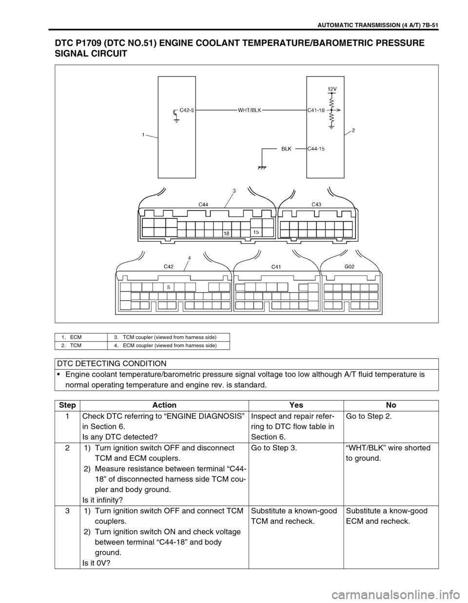
DTC P1709 (DTC NO.51) ENGINE COOLANT TEMPERATURE/BAROMETRIC PRESSURE
SIGNAL CIRCUIT
1. ECM 3. TCM coupler (viewed from harness side)
2. TCM 4. ECM coupler (viewed from harness side)
DTC DETECTING CONDITION
Engine coolant temperature/barometric pressure signal voltage too low although A/T fluid temperature is
normal operating temperature and engine rev. is standard.
Step Action Yes No
1 Check DTC referring to “ENGINE DIAGNOSIS”
in Section 6.
Is any DTC detected?Inspect and repair refer-
ring to DTC flow table in
Section 6.Go to Step 2.
2 1) Turn ignition switch OFF and disconnect
TCM and ECM couplers.
2) Measure resistance between terminal “C44-
18” of disconnected harness side TCM cou-
pler and body ground.
Is it infinity?Go to Step 3.“WHT/BLK” wire shorted
to ground.
3 1) Turn ignition switch OFF and connect TCM
couplers.
2) Turn ignition switch ON and check voltage
between terminal “C44-18” and body
ground.
Is it 0V?Substitute a known-good
TCM and recheck.Substitute a know-good
ECM and recheck.
Page 95 of 447

AUTOMATIC TRANSMISSION (4 A/T) 7B-53
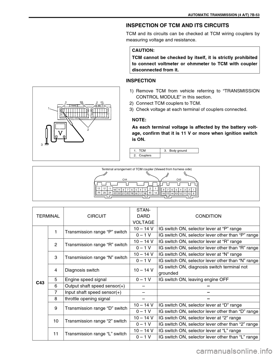
INSPECTION OF TCM AND ITS CIRCUITS
TCM and its circuits can be checked at TCM wiring couplers by
measuring voltage and resistance.
INSPECTION
1) Remove TCM from vehicle referring to “TRANSMISSION
CONTROL MODULE” in this section.
2) Connect TCM couplers to TCM.
3) Check voltage at each terminal of couplers connected.CAUTION:
TCM cannot be checked by itself, it is strictly prohibited
to connect voltmeter or ohmmeter to TCM with coupler
disconnected from it.
NOTE:
As each terminal voltage is affected by the battery volt-
age, confirm that it is 11 V or more when ignition switch
is ON.
1. TCM 3. Body ground
2. Couplers
TERMINAL CIRCUITSTAN-
DARD
VOLTAGECONDITION
C431 Transmission range “P” switch10 – 14 V IG switch ON, selector lever at “P” range
0 – 1 V IG switch ON, selector lever other than “P” range
2 Transmission range “R” switch10 – 14 V IG switch ON, selector lever at “R” range
0 – 1 V IG switch ON, selector lever other than “R” range
3 Transmission range “N” switch10 – 14 V IG switch ON, selector lever at “N” range
0 – 1 V IG switch ON, selector lever other than “N” range
4 Diagnosis switch 10 – 14 VIG switch ON, diagnosis switch terminal not
grounded
5 Engine speed signal 0 – 1 V IG switch ON, leaving engine OFF
6 Output shaft speed sensor(+)––
7 Input shaft speed sensor(+)––
8 throttle opening signal––
9 Transmission range “D” switch10 – 14 V IG switch ON, selector lever at “D” range
0 – 1 V IG switch ON, selector lever other than “D” range
10 Transmission range “2” switch10 – 14 V IG switch ON, selector lever at “2” range
0 – 1 V IG switch ON, selector lever other than “2” range
11 Transmission range “L” switch10 – 14 V IG switch ON, selector lever at “L” range
0 – 1 V IG switch ON, selector lever other than “L” range
Page 96 of 447

7B-54 AUTOMATIC TRANSMISSION (4 A/T)
C4312Serial data link (SUZUKI scan
tool)10 – 14 V IG switch ON
13Output shaft speed sensor
shield––
14 Output shaft speed sensor(–)––
15 Input shaft speed sensor(–)––
C442 IG power source 10 – 14 V IG switch ON
3Transmission temperature
sensor0 – 4.5 V IG switch ON
4 Brake switch 10 – 14 V IG switch ON, brake pedal depressed
5 A/C compressor0 – 2 V A/C OFF
10 – 14 V A/C ON
8 Idle up signal10 – 14 V Selector lever at “P” or “N” range
0 – 1 V Selector lever other than “P” or “N” range
10 Shift solenoid-A (No.1) 0 – 1 V IG switch ON, select lever at “P” range
11Shift solenoid-C (Dropping
resistor)0 – 1 V IG switch ON, select lever at “P” range
12Shift solenoid-D (Dropping
resistor)10 – 14 V IG switch ON, select lever at “P” range
13Shift solenoid-E (Dropping
resistor)0 – 1 V IG switch ON, select lever at “P” range
15 Ground––
16Transmission temperature
sensor ground––
17 O/D off switch0 – 1 V IG switch ON, O/D off switch ON
10 – 14 V IG switch ON, O/D off switch OFF
18Engine coolant temperature/
Barometric pressure signal––
20 A/T failure serial data 0 – 1 V IG switch ON
21 O/D OFF lamp10 – 14 V IG switch ON, O/D off switch OFF
0 – 1 V IG switch ON, O/D off switch ON
22 Lock-up solenoid 0 – 1 V IG switch ON, selector lever at “P” range
23 Shift solenoid-B (No.2) 0 – 1 V IG switch ON, selector lever at “P” range
24 Shift solenoid-C (No.3) 0 – 1 V IG switch ON, selector lever at “P” range
25 Shift solenoid-D (No.4) 2.2 – 4.9 V IG switch ON, selector lever at “P” range
26 Shift solenoid-E (No.5) 0 – 1 V IG switch ON, selector lever at “P” range TERMINAL CIRCUITSTAN-
DARD
VOLTAGECONDITION
Page 97 of 447

AUTOMATIC TRANSMISSION (4 A/T) 7B-55
ON-VEHICLE SERVICE
MAINTENANCE SERVICE
FLUID LEVEL AT NORMAL OPERATING TEMPERA-
TURE
INSPECTION
1) Stop vehicle and place it level.
2) Apply parking brake and place chocks against wheels.
3) With selector at P position, start engine.
4) Warm up engine till fluid temperature reaches normal oper-
ating temperature (70 – 80°C/158 – 176°F). As a guide to
check fluid temperature, warm up engine to normal operat-
ing temperature.
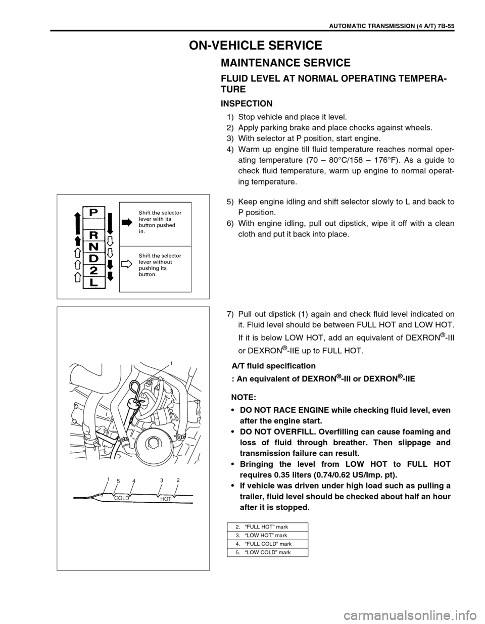
5) Keep engine idling and shift selector slowly to L and back to
P position.
6) With engine idling, pull out dipstick, wipe it off with a clean
cloth and put it back into place.
7) Pull out dipstick (1) again and check fluid level indicated on
it. Fluid level should be between FULL HOT and LOW HOT.
If it is below LOW HOT, add an equivalent of DEXRON
®-III
or DEXRON
®-IIE up to FULL HOT.
A/T fluid specification
: An equivalent of DEXRON
®-III or DEXRON®-IIE
NOTE:
DO NOT RACE ENGINE while checking fluid level, even
after the engine start.
DO NOT OVERFILL. Overfilling can cause foaming and
loss of fluid through breather. Then slippage and
transmission failure can result.
Bringing the level from LOW HOT to FULL HOT
requires 0.35 liters (0.74/0.62 US/Imp. pt).
If vehicle was driven under high load such as pulling a
trailer, fluid level should be checked about half an hour
after it is stopped.
2.“FULL HOT” mark
3.“LOW HOT” mark
4.“FULL COLD” mark
5.“LOW COLD” mark
1
Page 98 of 447
7B-56 AUTOMATIC TRANSMISSION (4 A/T)
FLUID LEVEL AT ROOM TEMPERATURE
INSPECTION
The fluid level check at room temperature performed after repair
or fluid change before test driving is just preparation for level
check of normal operation temperature. The checking procedure
itself is the same as that described previously. If the fluid level is
between FULL COLD and LOW COLD, proceed to test drive. And
when the fluid temperature has reached the normal operating
temperature, check fluid again and adjust it as necessary.
FLUID CHANGE
1) Lift up vehicle.
2) When engine has cooled down, remove drain plug (1) from
oil pan and drain A/T fluid.
3) Install drain plug.
Tightening torque
A/T fluid drain plug (a) : 23 N·m (2.3 kg-m, 16.5 lb-ft)
1. Dipstick
2.“FULL HOT” mark
3.“LOW HOT” mark
4.“FULL COLD” mark
5.“LOW COLD” mark
Page 101 of 447
AUTOMATIC TRANSMISSION (4 A/T) 7B-59
INSTALLATION
1) Using flat tip screwdriver, turn transmission range sensor to
have the match marks (1) line up (transmission range sensor
“N” range).
2) Turn selector lever (1) to “N” range (to have the automatic
transmission to “N” range).
3) Install transmission range sensor (1) to transmission case.
Tightening torque
Transmission range sensor bolt
(a) : 18 N·m (1.8 kg-m, 13.0 lb-ft)
4) Move selector lever in cabin to each range and check the
continuity of each terminal of transmission range sensor
referring to “INSPECTION”.
5) Connect transmission range sensor coupler.
6) Check that the engine can only be started in “N” and “P”
range, but can not in “D”, “2”, “L” or “R” range. Also, check
that backup lamp come ON at “R” range.
Page 106 of 447
7B-64 AUTOMATIC TRANSMISSION (4 A/T)
ENGINE COOLANT TEMP. (ECT) SENSOR
INSPECTION
Check engine coolant temp. sensor referring to Section 6E.
DROPPING RESISTOR
REMOVAL/INSTALLATION
Refer to the figure for removal/installation.
Tightening torque
Dropping resistor bolts
(a) : 20 N·m (2.0 kg-m, 14.5 lb-ft)
INSPECTION
Measure resistance between each resistor terminals.
Dropping resistor resistance
CIRCUIT RESISTANCE
Shift solenoid -C (No.3) 6.5 – 8.5
Ω
ΩΩ Ω
Shift solenoid -D (No.4) 6.5 – 8.5
Ω
ΩΩ Ω
Shift solenoid -E (No.5) 6.5 – 8.5
Ω
ΩΩ Ω
1. Resistor terminal for shift solenoid -C Circuit
2. Resistor terminal for shift solenoid -D Circuit
3. Resistor terminal for shift solenoid -E Circuit