Page 112 of 447

7B-70 AUTOMATIC TRANSMISSION (4 A/T)
LEARNING CONTROL INITIALIZATION
When one or more operations such as shown below are per-
formed, all learned contents which are stored in TCM memory
should be erased after the operations.
Replacing transmission with new or used one.
Repairing transmission partially by replacing any brake com-
ponent parts with new and/or used brake disc(s), plate(s)
and/or flange.
Repairing transmission partially by replacing any clutch com-
ponent parts with new and/or used clutch disc(s), plate(s)
and/or flange.
Replacing TCM with used one.
1) Turn ignition switch ON, leaving engine OFF.
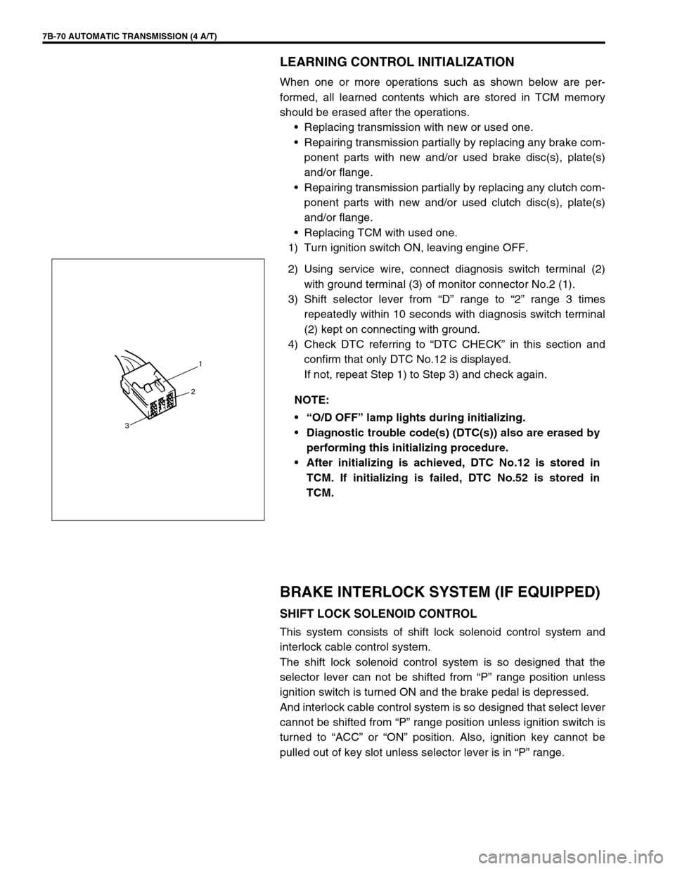
2) Using service wire, connect diagnosis switch terminal (2)
with ground terminal (3) of monitor connector No.2 (1).
3) Shift selector lever from “D” range to “2” range 3 times
repeatedly within 10 seconds with diagnosis switch terminal
(2) kept on connecting with ground.
4) Check DTC referring to “DTC CHECK” in this section and
confirm that only DTC No.12 is displayed.
If not, repeat Step 1) to Step 3) and check again.
BRAKE INTERLOCK SYSTEM (IF EQUIPPED)
SHIFT LOCK SOLENOID CONTROL
This system consists of shift lock solenoid control system and
interlock cable control system.
The shift lock solenoid control system is so designed that the
selector lever can not be shifted from “P” range position unless
ignition switch is turned ON and the brake pedal is depressed.
And interlock cable control system is so designed that select lever
cannot be shifted from “P” range position unless ignition switch is
turned to “ACC” or “ON” position. Also, ignition key cannot be
pulled out of key slot unless selector lever is in “P” range. NOTE:
“O/D OFF” lamp lights during initializing.
Diagnostic trouble code(s) (DTC(s)) also are erased by
performing this initializing procedure.
After initializing is achieved, DTC No.12 is stored in
TCM. If initializing is failed, DTC No.52 is stored in
TCM.
1
2
3
Page 118 of 447
7B-76 AUTOMATIC TRANSMISSION (4 A/T)
DISMOUNTING
1) Take down transmission with engine. For its procedure, refer
to Section 6A1.
2) For 4WD vehicle, remove transfer referring to Section 7D
For 2WD vehicle, remove engine rear mounting No.1
bracket and engine rear mounting No.2 bracket with stiff-
ener.
3) Remove torque converter housing lower plate (1).
4) Remove drive plate bolts.
To lock drive plate (1), engage a flat head rod or the like (2)
with drive plate gear.
5) Remove starting motor.
6) Remove bolts and nut fastening engine and transmission,
then detach transmission from engine.
NOTE:
When detaching transmission from engine, move it in
parallel with crankshaft and use care so as not to apply
excessive force to drive plate and torque converter.
WARNING:
Be sure to keep transmission with torque converter hori-
zontal or facing up throughout the work. Should it be
tilted with torque converter down, converter may fall off
and cause personal injury.
Page 119 of 447

AUTOMATIC TRANSMISSION (4 A/T) 7B-77
REMOUNTING
1) Make sure that torque converter is installed correctly to
transmission.
Refer to “UNIT ASSEMBLY” in this section.
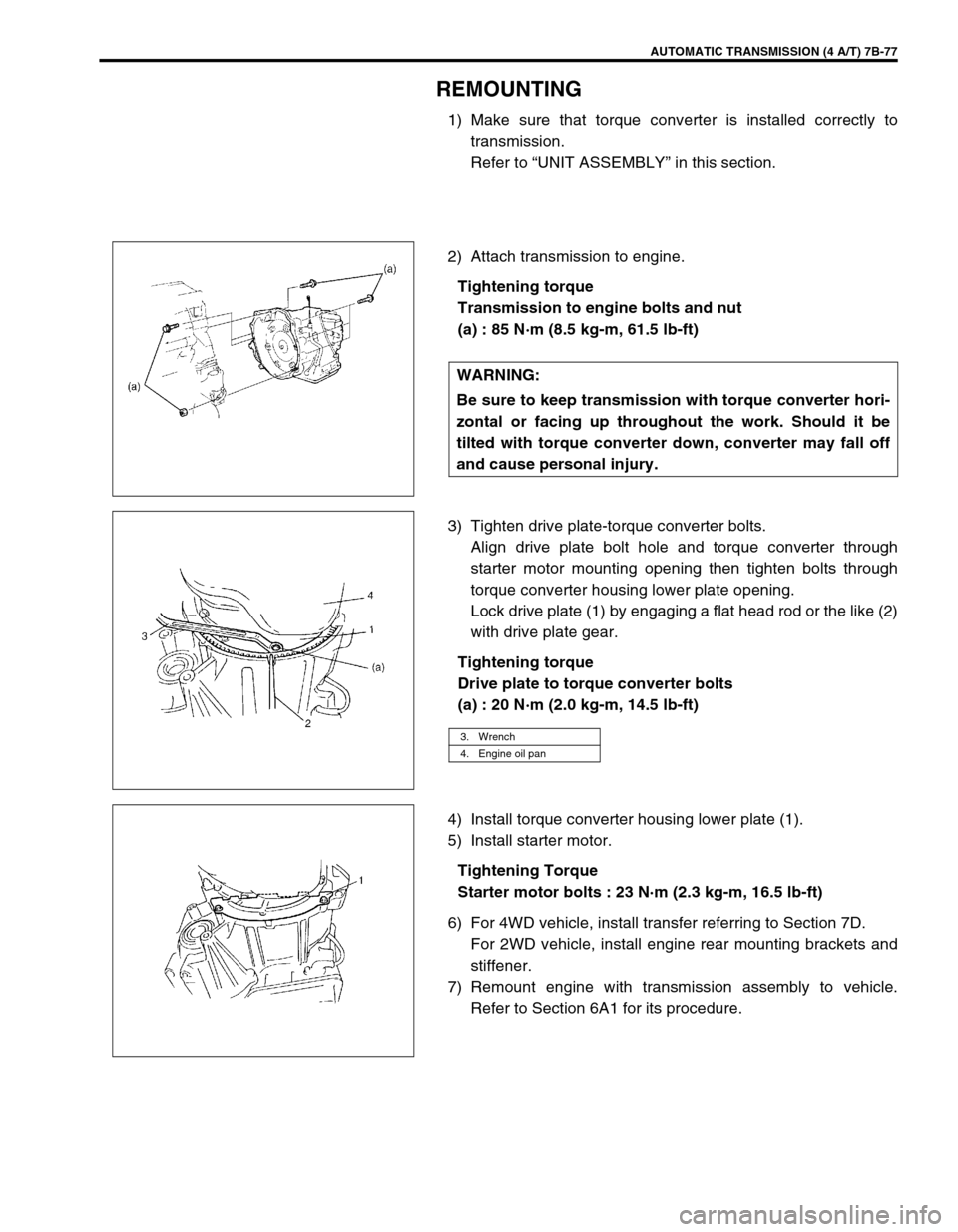
2) Attach transmission to engine.
Tightening torque
Transmission to engine bolts and nut
(a) : 85 N·m (8.5 kg-m, 61.5 lb-ft)
3) Tighten drive plate-torque converter bolts.
Align drive plate bolt hole and torque converter through
starter motor mounting opening then tighten bolts through
torque converter housing lower plate opening.
Lock drive plate (1) by engaging a flat head rod or the like (2)
with drive plate gear.
Tightening torque
Drive plate to torque converter bolts
(a) : 20 N·m (2.0 kg-m, 14.5 lb-ft)
4) Install torque converter housing lower plate (1).
5) Install starter motor.
Tightening Torque
Starter motor bolts : 23 N·m (2.3 kg-m, 16.5 lb-ft)
6) For 4WD vehicle, install transfer referring to Section 7D.
For 2WD vehicle, install engine rear mounting brackets and
stiffener.
7) Remount engine with transmission assembly to vehicle.
Refer to Section 6A1 for its procedure. WARNING:
Be sure to keep transmission with torque converter hori-
zontal or facing up throughout the work. Should it be
tilted with torque converter down, converter may fall off
and cause personal injury.
3. Wrench
4. Engine oil pan
Page 120 of 447
7B-78 AUTOMATIC TRANSMISSION (4 A/T)
UNIT DISASSEMBLY
1) Remove torque converter (1).
2) Remove engine mounting LH bracket.
3) Remove oil cooler (1) and battery ground cable (2) (if still
attached). CAUTION:
Thoroughly clean transmission exterior before over-
hauling it.
Keep working table, tools and hands clean while over-
hauling.
Use special care to handle aluminum parts so as not to
damage them.
Do not expose removed parts to dust. Keep them
always clean.
Page 176 of 447
7B-134 AUTOMATIC TRANSMISSION (4 A/T)
63) Install vehicle speed sensor (for speedometer) (1), shift
cable bracket (2) and connector clamp bracket (3).
Tightening torque
Vehicle speed sensor bolt
(a) : 5.5 N·m (0.55 kg-m, 4.0 lb-ft)
Shift cable bracket bolts
(b) : 13 N·m (1.3 kg-m, 9.5 lb-ft)
Connector clamp bracket bolt : 8 N·m (0.8 kg-m, 6.0 lb-ft)
64) Install A/T fluid filler tube (2) and level gauge (1).
Tightening torque
A/T fluid filler tube bolt (a) : 19.5 N·m (1.95 kg-m, 14.5 lb-ft)
65) Install output shaft speed sensor (1) and input shaft speed
sensor (2).
Apply grease to O-ring of each sensor.
Tightening torque
Output shaft speed sensor bolt
(a) : 8 N·m (0.8 kg-m, 6.0 lb-ft)
Input shaft speed sensor bolt
(b) : 8 N·m (0.8 kg-m, 6.0 Ib-ft)
Grease : 99000-25030
66) Install engine mounting LH bracket.
Tightening torque
Engine mounting LH bracket bolts
(a) : 55 N·m (5.5 kg-m, 40.0 lb-ft)
Page 178 of 447

7B-136 AUTOMATIC TRANSMISSION (4 A/T)
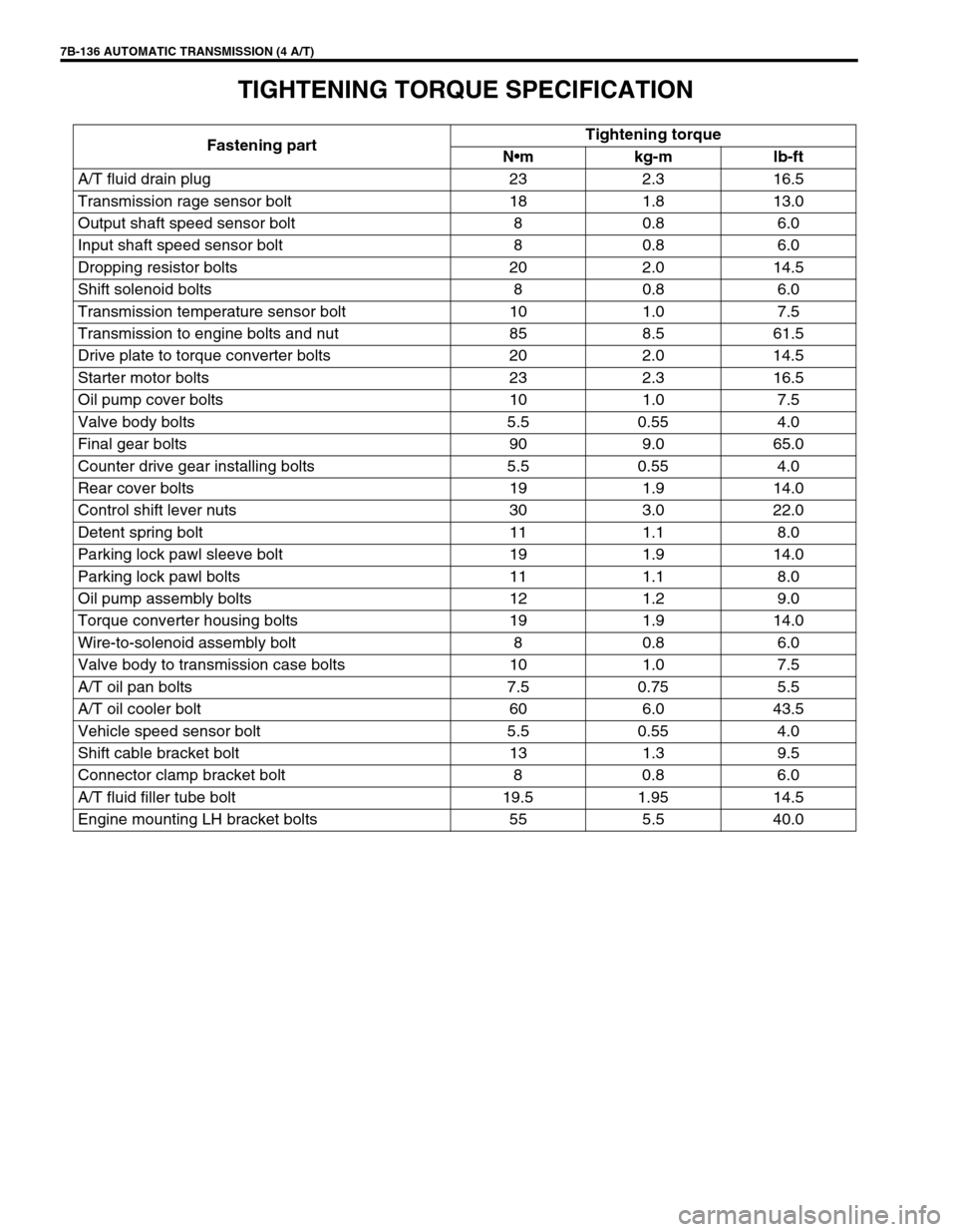
TIGHTENING TORQUE SPECIFICATION
Fastening partTightening torque
Nm kg-m lb-ft
A/T fluid drain plug 23 2.3 16.5
Transmission rage sensor bolt 18 1.8 13.0
Output shaft speed sensor bolt 8 0.8 6.0
Input shaft speed sensor bolt 8 0.8 6.0
Dropping resistor bolts 20 2.0 14.5
Shift solenoid bolts 8 0.8 6.0
Transmission temperature sensor bolt 10 1.0 7.5
Transmission to engine bolts and nut 85 8.5 61.5
Drive plate to torque converter bolts 20 2.0 14.5
Starter motor bolts 23 2.3 16.5
Oil pump cover bolts 10 1.0 7.5
Valve body bolts 5.5 0.55 4.0
Final gear bolts 90 9.0 65.0
Counter drive gear installing bolts 5.5 0.55 4.0
Rear cover bolts 19 1.9 14.0
Control shift lever nuts 30 3.0 22.0
Detent spring bolt 11 1.1 8.0
Parking lock pawl sleeve bolt 19 1.9 14.0
Parking lock pawl bolts 11 1.1 8.0
Oil pump assembly bolts 12 1.2 9.0
Torque converter housing bolts 19 1.9 14.0
Wire-to-solenoid assembly bolt 8 0.8 6.0
Valve body to transmission case bolts 10 1.0 7.5
A/T oil pan bolts 7.5 0.75 5.5
A/T oil cooler bolt 60 6.0 43.5
Vehicle speed sensor bolt 5.5 0.55 4.0
Shift cable bracket bolt 13 1.3 9.5
Connector clamp bracket bolt 8 0.8 6.0
A/T fluid filler tube bolt 19.5 1.95 14.5
Engine mounting LH bracket bolts 55 5.5 40.0
Page 185 of 447

CLUTCH 7C-3
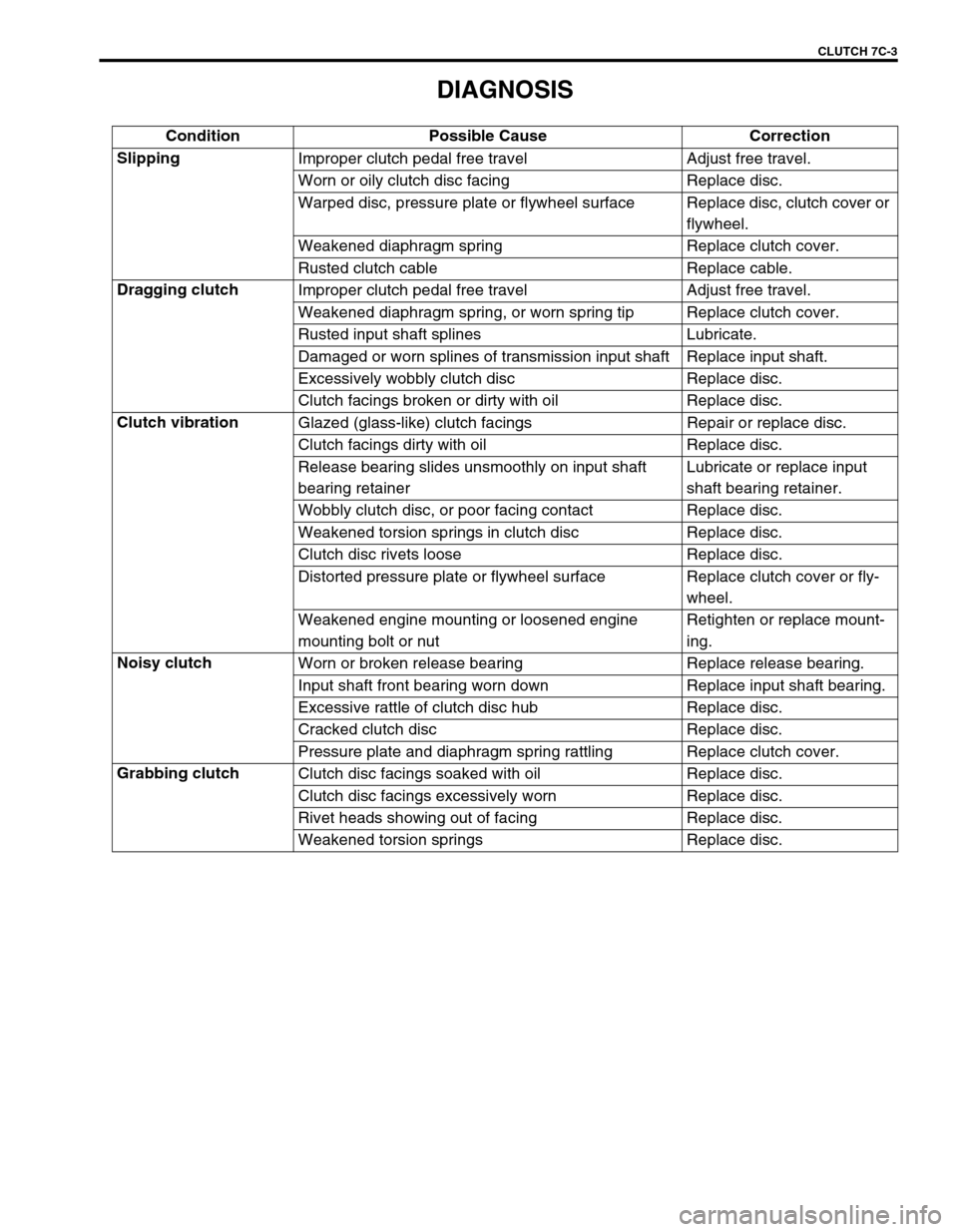
DIAGNOSIS
Condition Possible Cause Correction
Slipping
Improper clutch pedal free travel Adjust free travel.
Worn or oily clutch disc facing Replace disc.
Warped disc, pressure plate or flywheel surface Replace disc, clutch cover or
flywheel.
Weakened diaphragm spring Replace clutch cover.
Rusted clutch cable Replace cable.
Dragging clutch
Improper clutch pedal free travel Adjust free travel.
Weakened diaphragm spring, or worn spring tip Replace clutch cover.
Rusted input shaft splines Lubricate.
Damaged or worn splines of transmission input shaft Replace input shaft.
Excessively wobbly clutch disc Replace disc.
Clutch facings broken or dirty with oil Replace disc.
Clutch vibration
Glazed (glass-like) clutch facings Repair or replace disc.
Clutch facings dirty with oil Replace disc.
Release bearing slides unsmoothly on input shaft
bearing retainerLubricate or replace input
shaft bearing retainer.
Wobbly clutch disc, or poor facing contact Replace disc.
Weakened torsion springs in clutch disc Replace disc.
Clutch disc rivets loose Replace disc.
Distorted pressure plate or flywheel surface Replace clutch cover or fly-
wheel.
Weakened engine mounting or loosened engine
mounting bolt or nutRetighten or replace mount-
ing.
Noisy clutch
Worn or broken release bearing Replace release bearing.
Input shaft front bearing worn down Replace input shaft bearing.
Excessive rattle of clutch disc hub Replace disc.
Cracked clutch disc Replace disc.
Pressure plate and diaphragm spring rattling Replace clutch cover.
Grabbing clutch
Clutch disc facings soaked with oil Replace disc.
Clutch disc facings excessively worn Replace disc.
Rivet heads showing out of facing Replace disc.
Weakened torsion springs Replace disc.
Page 187 of 447
CLUTCH 7C-5
INSPECTION
Inspect clutch cable and replace it for any of the following condi-
tions.
Excessive cable friction
Frayed cable
Bent or kinked cable
Broken boots
Worn end
INSTALLATION
1) Apply grease to cable end hook and also joint pin before
installing cable.
“A” : Grease 99000-25010
2) Hook cable end with pedal by using screwdriver or long nose
pliers from cabin inside, then join inner cable wire joint pin in
release lever.
3) Install clutch cable (2) to bracket (3) by turning cable cap (1)
about 90° as shown.
4) Screw in joint nut and adjust free travel of pedal to specifica-
tion by turning nut.
5) Check clutch for proper function with engine running.
NOTE:
Take care that cable grommet (4) has specific installing
direction as shown in the figure.