2000 SUZUKI SWIFT torque
[x] Cancel search: torquePage 226 of 447
7F-4 REAR DIFFERENTIAL
ON-VEHICLE SERVICE
OIL CHANGE
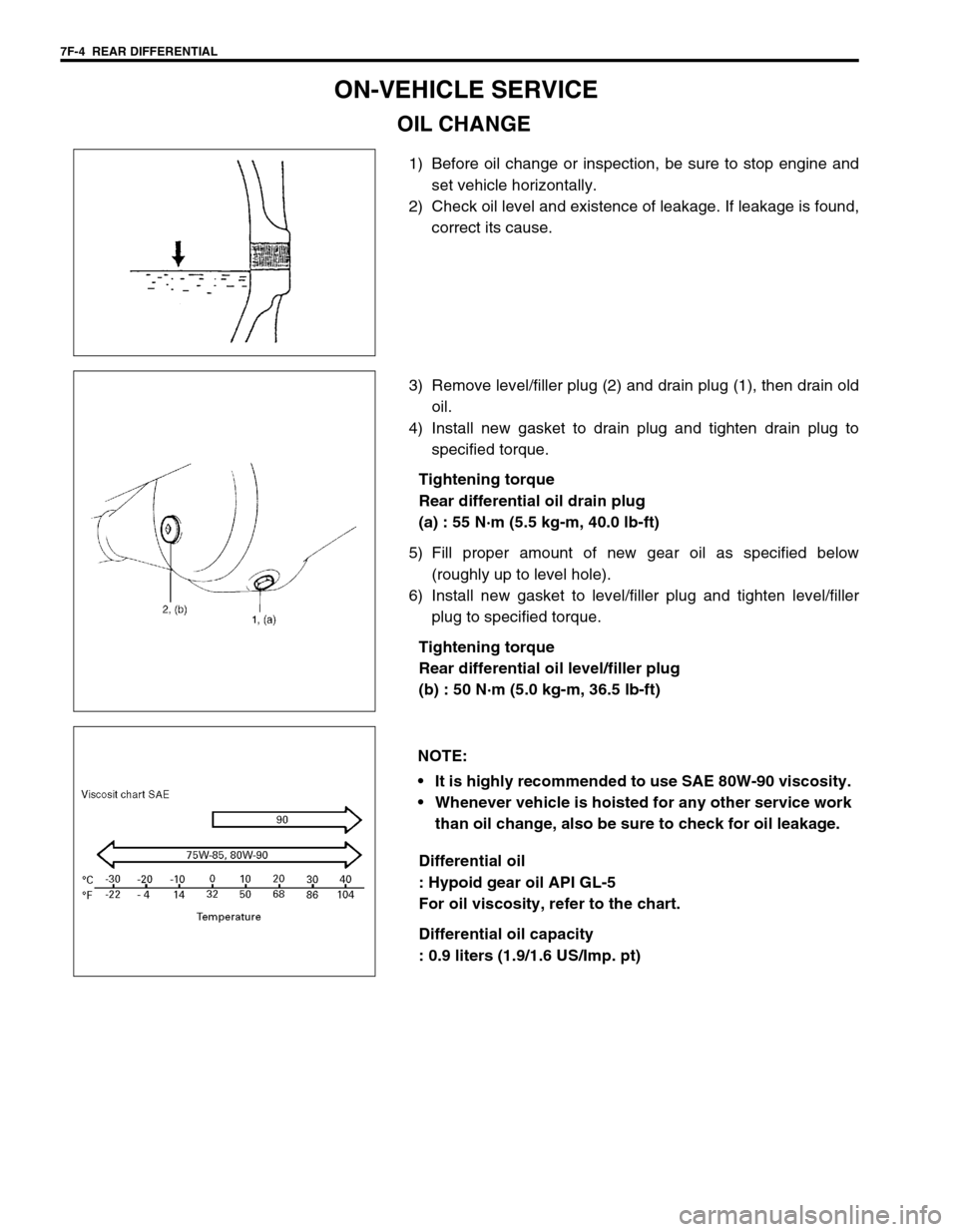
1) Before oil change or inspection, be sure to stop engine and
set vehicle horizontally.
2) Check oil level and existence of leakage. If leakage is found,
correct its cause.
3) Remove level/filler plug (2) and drain plug (1), then drain old
oil.
4) Install new gasket to drain plug and tighten drain plug to
specified torque.
Tightening torque
Rear differential oil drain plug
(a) : 55 N·m (5.5 kg-m, 40.0 lb-ft)
5) Fill proper amount of new gear oil as specified below
(roughly up to level hole).
6) Install new gasket to level/filler plug and tighten level/filler
plug to specified torque.
Tightening torque
Rear differential oil level/filler plug
(b) : 50 N·m (5.0 kg-m, 36.5 lb-ft)
Differential oil
: Hypoid gear oil API GL-5
For oil viscosity, refer to the chart.
Differential oil capacity
: 0.9 liters (1.9/1.6 US/Imp. pt)
NOTE:
It is highly recommended to use SAE 80W-90 viscosity.
Whenever vehicle is hoisted for any other service work
than oil change, also be sure to check for oil leakage.
Page 227 of 447
REAR DIFFERENTIAL 7F-5
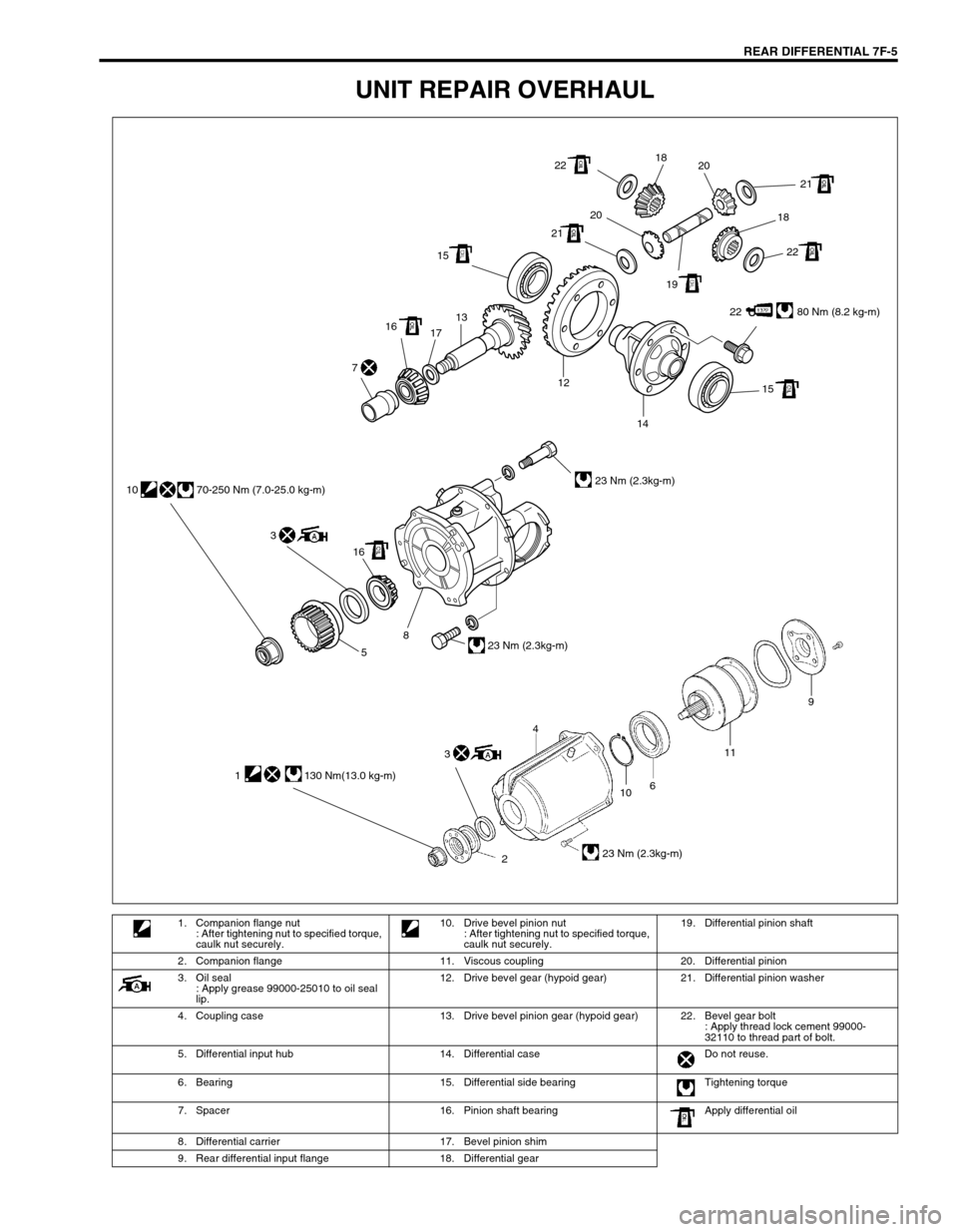
UNIT REPAIR OVERHAUL
22 80 Nm (8.2 kg-m) 1513
17 16
15 12
14 7
22
22 2121
2020
1918 18
16 3 10 70-250 Nm (7.0-25.0 kg-m)
23 Nm (2.3kg-m)
23 Nm (2.3kg-m)
8
5
10
2611
23 Nm (2.3kg-m)
9
4
1 130 Nm(13.0 kg-m)
3
1. Companion flange nut
: After tightening nut to specified torque,
caulk nut securely.10. Drive bevel pinion nut
: After tightening nut to specified torque,
caulk nut securely.19. Differential pinion shaft
2. Companion flange 11. Viscous coupling 20. Differential pinion
3. Oil seal
: Apply grease 99000-25010 to oil seal
lip.12. Drive bevel gear (hypoid gear) 21. Differential pinion washer
4. Coupling case 13. Drive bevel pinion gear (hypoid gear) 22. Bevel gear bolt
: Apply thread lock cement 99000-
32110 to thread part of bolt.
5. Differential input hub 14. Differential case Do not reuse.
6. Bearing 15. Differential side bearing Tightening torque
7. Spacer 16. Pinion shaft bearing Apply differential oil
8. Differential carrier 17. Bevel pinion shim
9. Rear differential input flange 18. Differential gear
Page 229 of 447
REAR DIFFERENTIAL 7F-7
REMOUNTING
Reverse removal procedure for installation, noting the following.
Rear Differential
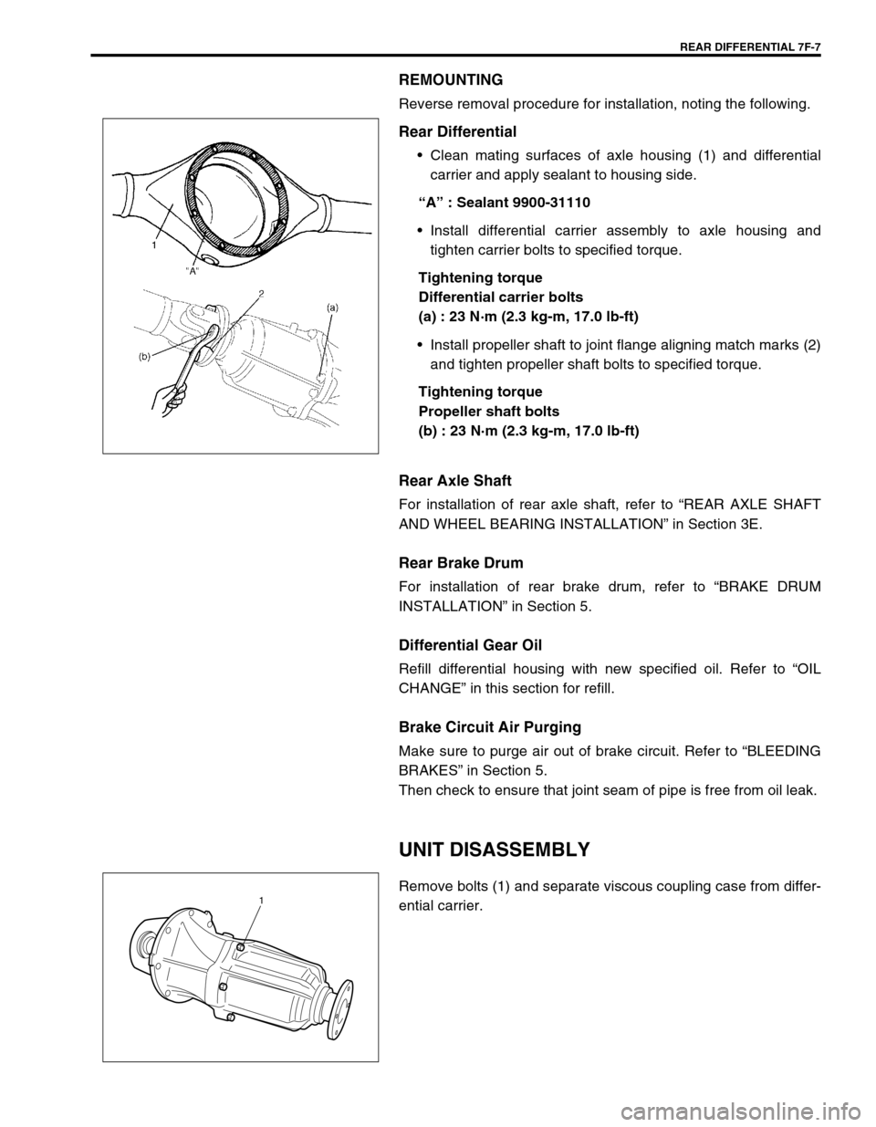
Clean mating surfaces of axle housing (1) and differential
carrier and apply sealant to housing side.
“A” : Sealant 9900-31110
Install differential carrier assembly to axle housing and
tighten carrier bolts to specified torque.
Tightening torque
Differential carrier bolts
(a) : 23 N·m (2.3 kg-m, 17.0 lb-ft)
Install propeller shaft to joint flange aligning match marks (2)
and tighten propeller shaft bolts to specified torque.
Tightening torque
Propeller shaft bolts
(b) : 23 N·m (2.3 kg-m, 17.0 lb-ft)
Rear Axle Shaft
For installation of rear axle shaft, refer to “REAR AXLE SHAFT
AND WHEEL BEARING INSTALLATION” in Section 3E.
Rear Brake Drum
For installation of rear brake drum, refer to “BRAKE DRUM
INSTALLATION” in Section 5.
Differential Gear Oil
Refill differential housing with new specified oil. Refer to “OIL
CHANGE” in this section for refill.
Brake Circuit Air Purging
Make sure to purge air out of brake circuit. Refer to “BLEEDING
BRAKES” in Section 5.
Then check to ensure that joint seam of pipe is free from oil leak.
UNIT DISASSEMBLY
Remove bolts (1) and separate viscous coupling case from differ-
ential carrier.1
Page 231 of 447
REAR DIFFERENTIAL 7F-9
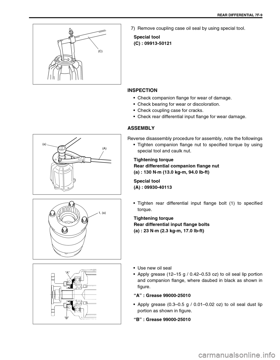
7) Remove coupling case oil seal by using special tool.
Special tool
(C) : 09913-50121
INSPECTION
Check companion flange for wear of damage.
Check bearing for wear or discoloration.
Check coupling case for cracks.
Check rear differential input flange for wear damage.
ASSEMBLY
Reverse disassembly procedure for assembly, note the followings
Tighten companion flange nut to specified torque by using
special tool and caulk nut.
Tightening torque
Rear differential companion flange nut
(a) : 130 N·m (13.0 kg-m, 94.0 lb-ft)
Special tool
(A) : 09930-40113
Tighten rear differential input flange bolt (1) to specified
torque.
Tightening torque
Rear differential input flange bolts
(a) : 23 N·m (2.3 kg-m, 17.0 lb-ft)
Use new oil seal
Apply grease (12–15 g / 0.42–0.53 oz) to oil seal lip portion
and companion flange, where daubed in black as shown in
figure.
“A” : Grease 99000-25010
Apply grease (0.3–0.5 g / 0.01–0.02 oz) to oil seal dust lip
portion as shown in figure.
“B” : Grease 99000-25010
(C)
(a)
(A)
1, (a)
Page 235 of 447

REAR DIFFERENTIAL 7F-13
2) If thrust play is out of specification, select suitable side
washer from among following available size, install it and
check again that specified gear play is obtained.
Available side washer thickness
0.90, 1.00 and 1.10 mm (0.035, 0.039 and 0.043 in.)
3) Put drive bevel gear (1) on differential case (2) and fasten
them with bolts (3) by tightening them to specified torque.
Use thread lock cement for bolts (3).
“A” : Thread lock cement 99000-32110
Tightening torque
Drive bevel gear bolts (a) : 80 N·m (8.0 kg-m, 58.0 lb-ft)
4) Press-fit differential side bearings (3) to differential case (1)
by using special tools.
Special tool
(A) : 09951-76010
(B) : 09951-16060 CAUTION:
Use of any other bolts than that specified is prohibited.
2
1 3, “A”, (a)
2. Drive bevel gear
Page 239 of 447
REAR DIFFERENTIAL 7F-17
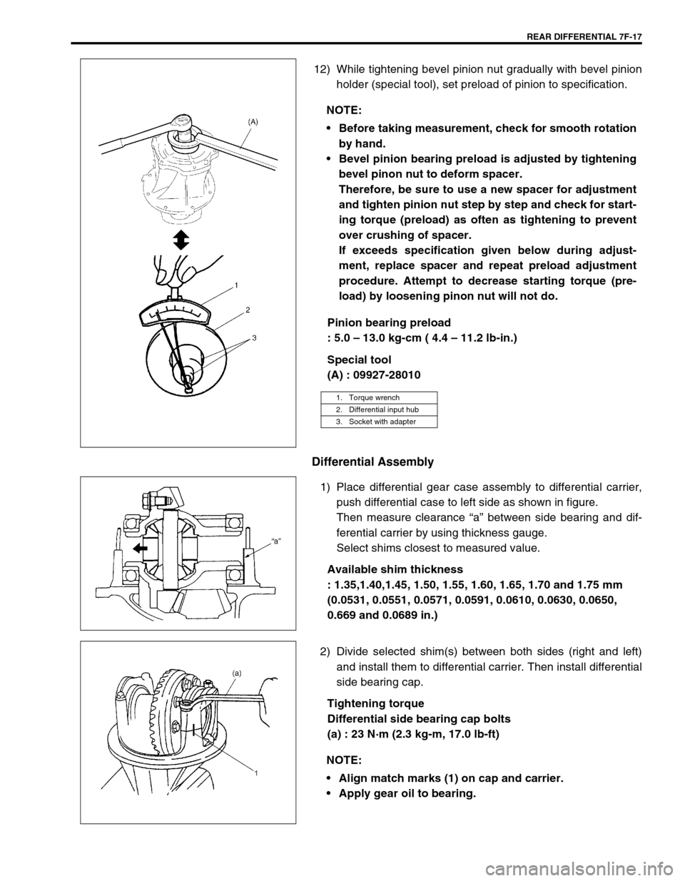
12) While tightening bevel pinion nut gradually with bevel pinion
holder (special tool), set preload of pinion to specification.
Pinion bearing preload
: 5.0 – 13.0 kg-cm ( 4.4 – 11.2 lb-in.)
Special tool
(A) : 09927-28010
Differential Assembly
1) Place differential gear case assembly to differential carrier,
push differential case to left side as shown in figure.
Then measure clearance “a” between side bearing and dif-
ferential carrier by using thickness gauge.
Select shims closest to measured value.
Available shim thickness
: 1.35,1.40,1.45, 1.50, 1.55, 1.60, 1.65, 1.70 and 1.75 mm
(0.0531, 0.0551, 0.0571, 0.0591, 0.0610, 0.0630, 0.0650,
0.669 and 0.0689 in.)
2) Divide selected shim(s) between both sides (right and left)
and install them to differential carrier. Then install differential
side bearing cap.
Tightening torque
Differential side bearing cap bolts
(a) : 23 N·m (2.3 kg-m, 17.0 lb-ft) NOTE:
Before taking measurement, check for smooth rotation
by hand.
Bevel pinion bearing preload is adjusted by tightening
bevel pinon nut to deform spacer.
Therefore, be sure to use a new spacer for adjustment
and tighten pinion nut step by step and check for start-
ing torque (preload) as often as tightening to prevent
over crushing of spacer.
If exceeds specification given below during adjust-
ment, replace spacer and repeat preload adjustment
procedure. Attempt to decrease starting torque (pre-
load) by loosening pinon nut will not do.
1. Torque wrench
2. Differential input hub
3. Socket with adapter
NOTE:
Align match marks (1) on cap and carrier.
Apply gear oil to bearing.
Page 242 of 447
7F-20 REAR DIFFERENTIAL
UNIT ASSEMBLY
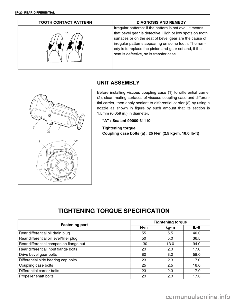
Before installing viscous coupling case (1) to differential carrier
(2), clean mating surfaces of viscous coupling case and differen-
tial carrier, then apply sealant to differential carrier (2) by using a
nozzle as shown in figure by such amount that its section is
1.5mm (0.059 in.) in diameter.
“A” : Sealant 99000-31110
Tightening torque
Coupling case bolts (a) : 25 N·m (2.5 kg-m, 18.0 lb-ft)
TIGHTENING TORQUE SPECIFICATION
Irregular patterns: If the pattern is not oval, it means
that bevel gear is defective. High or low spots on tooth
surfaces or on the seat of bevel gear are the cause of
irregular patterns appearing on some teeth. The rem-
edy is to replace the pinion and-gear set and, if the
seat is defective, so is transfer case. TOOTH CONTACT PATTERN DIAGNOSIS AND REMEDY
Fastening partTightening torque
Nm kg-m lb-ft
Rear differential oil drain plug 55 5.5 40.0
Rear differential oil level/filler plug 50 5.0 36.5
Rear differential companion flange nut 130 13.0 94.0
Rear differential input flange bolts 23 2.3 17.0
Drive bevel gear bolts 80 8.0 58.0
Differential side bearing cap bolts 23 2.3 17.0
Coupling case bolts 25 2.5 18.0
Differential carrier bolts 23 2.3 17.0
Propeller shaft bolts 23 2.3 17.0
Page 305 of 447
BODY SERVICE 9-1
6F1
6F2
6G
6H
6K
7A
7A1
7B1
7C1
7D
7E
7F
8A
8B
8C
8D
8E
9
10
10A
10B
SECTION 9
BODY SERVICE
CONTENTS
GLASS, WINDOWS AND MIRRORS ................. 9-2
FRONT DOOR GLASS ................................... 9-2
FRONT DOOR WINDOW REGULATOR ........ 9-6
DOOR MIRROR .......................................... 9-7
REAR DOOR GLASS (IF EQUIPPED) ....... 9-8
REAR DOOR WINDOW REGULATOR ........ 9-11
WINDOW SHIELD ........................................ 9-12
QUARTER WINDOW .................................... 9-17
BACK DOOR GLASS .................................... 9-18
BODY STRUCTURE......................................... 9-19
FRONT DOOR ASSEMBLY .......................... 9-19
REAR DOOR ASSEMBLY ............................ 9-22
BACK DOOR ASSEMBLY ............................ 9-23
HOOD ........................................................... 9-25
FRONT FENDER .......................................... 9-26
FRONT BUMPER AND REAR BUMPER...... 9-27
ROOF RAIL (IF EQUIPPED) ......................... 9-28
BODY DIMENSIONS .................................... 9-29
ENGINE ROOM ........................................ 9-29
BACK DOOR ............................................. 9-30
SIDE BODY ............................................... 9-31UNDER BODY .......................................... 9-34
PANEL CLEARANCE ................................... 9-36
INSTRUMENTATION AND DRIVER
INFORMATION................................................. 9-38
INSTRUMENT PANEL .................................. 9-38
SEATS .............................................................. 9-40
FRONT SEAT ............................................... 9-40
REAR SEAT.................................................. 9-41
SECURITY AND LOCKS ................................. 9-42
FRONT DOOR LOCK ASSEMBLY............... 9-42
REAR DOOR LOCK ASSEMBLY (IF
EQUIPPED) .................................................. 9-44
BACK DOOR LOCK ASSEMBLY ................. 9-45
KEY CODING ............................................... 9-46
KEY USAGE AND IDENTIFICATION ....... 9-46
IGNITION SWITCH LOCK CYLINDER ..... 9-47
EXTERIOR AND INTERIOR TRIM ................... 9-47
FLOOR CARPET .......................................... 9-47
HEAD LINING ............................................... 9-48
PAINT AND COATINGS .................................. 9-50 WARNING:
For vehicles equipped with Supplemental Restraint (Air Bag) System:
Service on and around the air bag system components or wiring must be performed only by an
authorized SUZUKI dealer. Refer to “Air Bag System Components and Wiring Location View” under
“General Description” in air bag system section in order to confirm whether you are performing ser-
vice on or near the air bag system components or wiring. Please observe all WARNINGS and “Ser-
vice Precautions” under “On-Vehicle Service” in air bag system section before performing service
on or around the air bag system components or wiring. Failure to follow WARNINGS could result in
unintentional activation of the system or could render the system inoperative. Either of these two
conditions may result in severe injury.
Technical service work must be started at least 90 seconds after the ignition switch is turned to the
“LOCK” position and the negative cable is disconnected from the battery. Otherwise, the system
may be activated by reserve energy in the Sensing and Diagnostic Module (SDM).
When body servicing, if shock may be applied to air bag system component parts, remove those
parts beforehand. (Refer to Section 10B.)
NOTE:
Fasteners are important attaching parts in that they could affect the performance of vital components
and systems, and / or could result in major repair expense. They must be replaced with one of the
same part number of with an equivalent part if replacement becomes necessary.
Do not use a replacement part of lesser quality or substitute a design. Torque values must be used as
specified during reassembly to assure proper retention of these parts.