Page 203 of 447
TRANSFER 7D-5
UNIT DISMOUNTING
1) Disconnect negative cable at battery.
2) Hoist vehicle and remove wheels.
3) Drain transmission oil.
4) Remove exhaust No.1 pipe (1).
5) Remove propeller shaft.
6) Remove right side drive shaft (1) refer to Section 4A.
7) Remove Stiffener (3).
8) With transmission assembly held on jack, remove rear
mounting bolts (1).
9) Remove transfer mounting bolts and draw out transfer
assembly from transmission assembly.
2. Exhaust No.2 pipe
12
1
1. Transfer
2. Transmission
1
Page 206 of 447
7D-8 TRANSFER
5) Remove driven gear bearing outer race from left case (1) by
using special tool.
Special tool
(A) : 09941-54911
6) Remove driven gear bearing outer race from right case (1)
by using special tool.
Special tool
(A) : 09941-54911
INTERMEDIATE SHAFT
1) Remove reduction drive oil seal and snap ring, and then
drive out intermediate shaft.
2) Drive out intermediate right bearing (1) from intermediate
shaft by using bearing puller and press.
3) Remove intermediate center oil seals (1) by using press and
special tools.
Special tool
(A) : 09924-84510-005
(B) : 09913-75821
Page 207 of 447
TRANSFER 7D-9
TRANSFER OUTPUT RETAINER
1) Uncaulk flange nut.
2) Remove flange nut while holding flange (2) by using special
tool.
Special tool
(A) : 09930-40113
3) Remove flange (1) by special tool.
Special tool
(A) : 09913-65135
4) Drive out bevel pinion shaft from transfer output retainer by
tapping with plastic hammer.
5) Drive out pinion spacer from bevel pinion shaft.
6) Drive out pinion shaft bearing (2) from bevel pinion shaft (1)
by using press.
7) Remove pinion shaft oil seal (1) by using special tool.
Special tool
(A) : 09913-50121
1. Power wrench
3. Bearing puller
Page 208 of 447

7D-10 TRANSFER
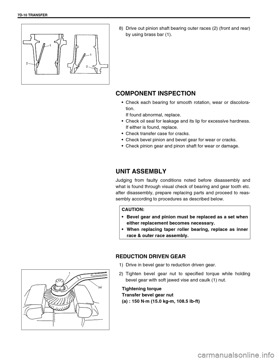
8) Drive out pinion shaft bearing outer races (2) (front and rear)
by using brass bar (1).
COMPONENT INSPECTION
Check each bearing for smooth rotation, wear or discolora-
tion.
If found abnormal, replace.
Check oil seal for leakage and its lip for excessive hardness.
If either is found, replace.
Check transfer case for cracks.
Check bevel pinion and bevel gear for wear or cracks.
Check pinion gear and pinon shaft for wear or damage.
UNIT ASSEMBLY
Judging from faulty conditions noted before disassembly and
what is found through visual check of bearing and gear tooth etc.
after disassembly, prepare replacing parts and proceed to reas-
sembly according to procedures as described below.
REDUCTION DRIVEN GEAR
1) Drive in bevel gear to reduction driven gear.
2) Tighten bevel gear nut to specified torque while holding
bevel gear with soft jawed vise and caulk (1) nut.
Tightening torque
Transfer bevel gear nut
(a) : 150 N·m (15.0 kg-m, 108.5 lb-ft)
CAUTION:
Bevel gear and pinion must be replaced as a set when
either replacement becomes necessary.
When replacing taper roller bearing, replace as inner
race & outer race assembly.
Page 211 of 447

TRANSFER 7D-13
To engage bevel pinion and gear correctly, it is prerequired to
install bevel pinion to transfer output retainer properly by using
adjusting shim (bevel pinion shim) as described on following
pages.
Shown in above page are relative positions of bevel pinion, gear
and transfer output retainer.
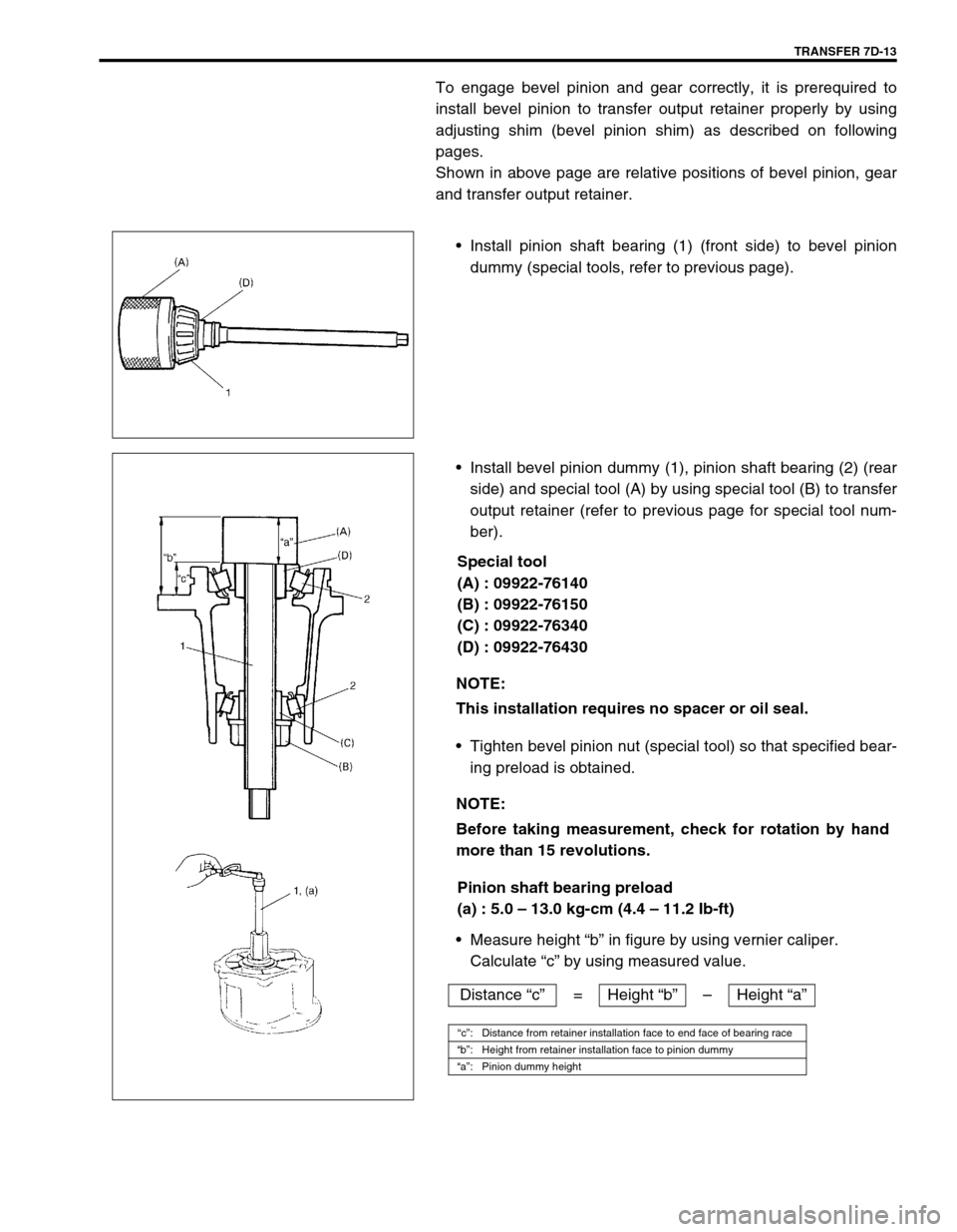
Install pinion shaft bearing (1) (front side) to bevel pinion
dummy (special tools, refer to previous page).
Install bevel pinion dummy (1), pinion shaft bearing (2) (rear
side) and special tool (A) by using special tool (B) to transfer
output retainer (refer to previous page for special tool num-
ber).
Special tool
(A) : 09922-76140
(B) : 09922-76150
(C) : 09922-76340
(D) : 09922-76430
Tighten bevel pinion nut (special tool) so that specified bear-
ing preload is obtained.
Pinion shaft bearing preload
(a) : 5.0 – 13.0 kg-cm (4.4 – 11.2 Ib-ft)
Measure height “b” in figure by using vernier caliper.
Calculate “c” by using measured value.
NOTE:
This installation requires no spacer or oil seal.
NOTE:
Before taking measurement, check for rotation by hand
more than 15 revolutions.
Distance “c”= Height “b”–Height “a”
“c”: Distance from retainer installation face to end face of bearing race
“b”: Height from retainer installation face to pinion dummy
“a”: Pinion dummy height
Page 213 of 447

TRANSFER 7D-15
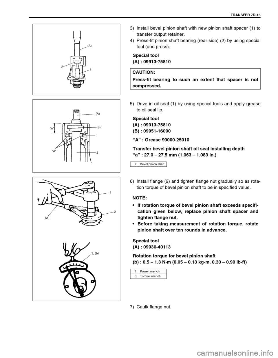
3) Install bevel pinion shaft with new pinion shaft spacer (1) to
transfer output retainer.
4) Press-fit pinion shaft bearing (rear side) (2) by using special
tool (and press).
Special tool
(A) : 09913-75810
5) Drive in oil seal (1) by using special tools and apply grease
to oil seal lip.
Special tool
(A) : 09913-75810
(B) : 09951-16090
“A” : Grease 99000-25010
Transfer bevel pinion shaft oil seal installing depth
“a” : 27.0 – 27.5 mm (1.063 – 1.083 in.)
6) Install flange (2) and tighten flange nut gradually so as rota-
tion torque of bevel pinion shaft to be in specified value.
Special tool
(A) : 09930-40113
Rotation torque for bevel pinion shaft
(b) : 0.5 – 1.3 N·m (0.05 – 0.13 kg-m, 0.30 – 0.90 lb-ft)
7) Caulk flange nut.CAUTION:
Press-fit bearing to such an extent that spacer is not
compressed.
2. Bevel pinion shaft
NOTE:
If rotation torque of bevel pinion shaft exceeds specifi-
cation given below, replace pinion shaft spacer and
tighten flange nut.
Before taking measurement of rotation torque, rotate
pinion shaft over ten rounds in advance.
1. Power wrench
3. Torque wrench
Page 214 of 447

7D-16 TRANSFER
RIGHT CASE
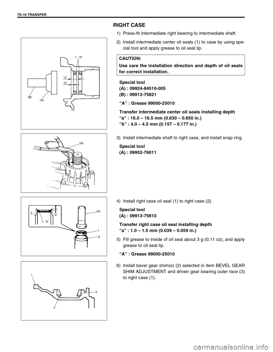
1) Press-fit intermediate right bearing to intermediate shaft.
2) Install intermediate center oil seals (1) to case by using spe-
cial tool and apply grease to oil seal lip.
Special tool
(A) : 09924-84510-005
(B) : 09913-75821
“A” : Grease 99000-25010
Transfer intermediate center oil seals installing depth
“a” : 16.0 – 16.5 mm (0.630 – 0.650 in.)
“b” : 4.0 – 4.5 mm (0.157 – 0.177 in.)
3) Install intermediate shaft to right case, and install snap ring.
Special tool
(A) : 09952-76011
4) Install right case oil seal (1) to right case (2).
Special tool
(A) : 09913-75810
Transfer right case oil seal installing depth
“a” : 1.0 – 1.5 mm (0.039 – 0.059 in.)
5) Fill grease to inside of oil seal about 3 g (0.11 oz), and apply
grease to oil seal lip.
“A” : Grease 99000-25010
6) Install bevel gear shim(s) (2) selected in item BEVEL GEAR
SHIM ADJUSTMENT and driven gear bearing outer race (3)
to right case (1). CAUTION:
Use care the installation direction and depth of oil seals
for correct installation.
Page 215 of 447
TRANSFER 7D-17
LEFT CASE
1) Install the bevel gear shim(s) selected in item BEVEL GEAR
SHIM ADJUSTMENT and driven gear bearing outer race to
left case.
2) Install reduction drive gear oil seal (1) to left case (2) by
using special tool.
Special tool
(A) : 09913-75810
Transfer reduction drive gear oil seal installing depth
“a” : 1.5 – 2.0 mm (0.059 – 0.078 in.)
3) Fill grease to inside of oil seal about 3 g (0.11 oz), and apply
grease to oil seal lip.
“A” : Grease 99000-25010
4) Press-fit drive gear bearings (right (2) and left (3)) to reduc-
tion drive gear (1).
Apply gear oil to ball part of bearing.
5) Install reduction drive gear (2) and reduction driven gear (3)
to left case (1).
TRANSFER ASSEMBLY
1) Clean mating surface of right case and left case (1), and
apply sealant to left case (1) by using a nozzle as shown in
figure by such amount that its section is 1.5mm (0.059 in) in
diameter.
“A” : Sealant 99000-31230