2000 SUZUKI SWIFT warning
[x] Cancel search: warningPage 287 of 698

5-14 BRAKES
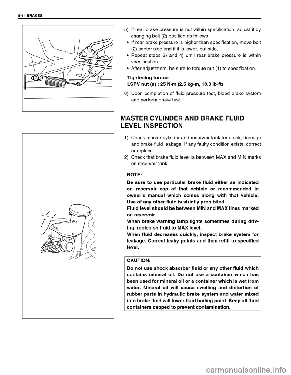
5) If rear brake pressure is not within specification, adjust it by
changing bolt (2) position as follows.
If rear brake pressure is higher than specification, move bolt
(2) center side and if it is lower, out side.
Repeat steps 3) and 4) until rear brake pressure is within
specification.
After adjustment, be sure to torque nut (1) to specification.
Tightening torque
LSPV nut (a) : 25 N·m (2.5 kg-m, 18.0 lb-ft)
6) Upon completion of fluid pressure test, bleed brake system
and perform brake test.
MASTER CYLINDER AND BRAKE FLUID
LEVEL INSPECTION
1) Check master cylinder and reservoir tank for crack, damage
and brake fluid leakage. If any faulty condition exists, correct
or replace.
2) Check that brake fluid level is between MAX and MIN marks
on reservoir tank.
2
1, (a)
NOTE:
Be sure to use particular brake fluid either as indicated
on reservoir cap of that vehicle or recommended in
owner’s manual which comes along with that vehicle.
Use of any other fluid is strictly prohibited.
Fluid level should be between MIN and MAX lines marked
on reservoir.
When brake warning lamp lights sometimes during driv-
ing, replenish fluid to MAX level.
When fluid decreases quickly, inspect brake system for
leakage. Correct leaky points and then refill to specified
level.
CAUTION:
Do not use shock absorber fluid or any other fluid which
contains mineral oil. Do not use a container which has
been used for mineral oil or a container which is wet from
water. Mineral oil will cause swelling and distortion of
rubber parts in hydraulic brake system and water mixed
into brake fluid will lower fluid boiling point. Keep all fluid
containers capped to prevent contamination.
MAX
MIN
Page 293 of 698

5-20 BRAKES
DISASSEMBLY
1) Remove piston with air blown into flexible hose bolt installa-
tion hole.
2) Remove cylinder boot (1).
3) Remove piston seal using a thin blade like a thickness
gauge, etc.
4) Remove bleeder plug and cap from caliper.
INSPECTION
Pin Boot and Cylinder Boot
Check boots for breakage, crack and damage.
If defective, replace.CAUTION:
Clean around caliper with brake fluid before disassem-
bly.
WARNING:
Do not apply too highly compressed air which will cause
piston to jump out of cylinder. Place a cloth (1) to prevent
piston from damage. It should be taken out gradually
with moderately compressed air. Do not place your fin-
gers in front of piston when using compressed air.
CAUTION:
Use care not to cause damage to cylinder boot.
1
CAUTION:
Be careful not to damage inside (bore side) of cylinder.
Page 296 of 698

BRAKES 5-23
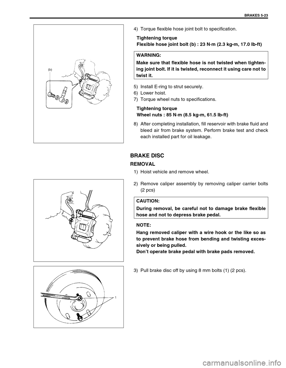
4) Torque flexible hose joint bolt to specification.
Tightening torque
Flexible hose joint bolt (b) : 23 N·m (2.3 kg-m, 17.0 Ib-ft)
5) Install E-ring to strut securely.
6) Lower hoist.
7) Torque wheel nuts to specifications.
Tightening torque
Wheel nuts : 85 N·m (8.5 kg-m, 61.5 Ib-ft)
8) After completing installation, fill reservoir with brake fluid and
bleed air from brake system. Perform brake test and check
each installed part for oil leakage.
BRAKE DISC
REMOVAL
1) Hoist vehicle and remove wheel.
2) Remove caliper assembly by removing caliper carrier bolts
(2 pcs)
3) Pull brake disc off by using 8 mm bolts (1) (2 pcs).WARNING:
Make sure that flexible hose is not twisted when tighten-
ing joint bolt. If it is twisted, reconnect it using care not to
twist it.
CAUTION:
During removal, be careful not to damage brake flexible
hose and not to depress brake pedal.
NOTE:
Hang removed caliper with a wire hook or the like so as
to prevent brake hose from bending and twisting exces-
sively or being pulled.
Don’t operate brake pedal with brake pads removed.
Page 326 of 698

ANTILOCK BRAKE SYSTEM (ABS) 5E-1
6F1
6F2
6G
6H
6K
7A
7A1
7B1
7C1
7D
7E
7F
8A
8B
8C
8D
8E
5E
9
10
10A
10B
SECTION 5E
ANTILOCK BRAKE SYSTEM (ABS)
CONTENTS
GENERAL DESCRIPTION .............................. 5E-2
COMPONENTS/PARTS LOCATION AND
BRAKE HOSE/PIPE ROUTING ................... 5E-2
SYSTEM SCHEMATIC ................................ 5E-4
ABS HYDRAULIC UNIT/CONTROL
MODULE ASSEMBLY ................................. 5E-5
SELF-DIAGNOSIS FUNCTION................ 5E-5
FAIL-SAFE FUNCTION............................ 5E-5
SYSTEM CIRCUIT ....................................... 5E-6
DIAGNOSIS ..................................................... 5E-8
PRECAUTION IN DIAGNOSING
TROUBLES .................................................. 5E-8
ABS DIAGNOSTIC FLOW TABLE ............... 5E-9
ABS WARNING LAMP CHECK ................. 5E-12
EBD WARNING LAMP (BRAKE
WARNING LAMP) CHECK ........................ 5E-12
TABLE – A ABS WARNING LAMP
CIRCUIT CHECK – LAMP DOES NOT
COME “ON” AT IGNITION SWITCH ON.... 5E-13
TABLE – B ABS WARNING LAMP
CIRCUIT CHECK – LAMP COMES
“ON” STEADY ............................................ 5E-14TABLE – C ABS WARNING LAMP
CIRCUIT CHECK – THE LAMP FLASHES
CONTINUOUSLY WHILE IGNITION
SWITCH IS ON .......................................... 5E-15
TABLE – D CODE (DTC) IS NOT
OUTPUTTED EVEN WITH DIAGNOSIS
SWITCH TERMINAL CONNECTED TO
GROUND ................................................... 5E-16
TABLE – E EBD WARNING LAMP
(BRAKE WARNING LAMP) CHECK
– LAMP COMES “ON” STEADY ................ 5E-17
DIAGNOSTIC TROUBLE CODE
(DTC) CHECK (USING ABS WARNING
LAMP) ........................................................ 5E-18
DIAGNOSTIC TROUBLE CODE (DTC)
CHECK (USING SUZUKI SCAN TOOL).... 5E-19
DIAGNOSTIC TROUBLE CODE
(DTC) CLEARANCE .................................. 5E-19
DIAGNOSTIC TROUBLE CODE (DTC)
TABLE........................................................ 5E-20
DTC C1013 (DTC 13) – SYSTEM
SPECIFICATIONS DIFFERENT FROM ABS
CONTROL MODULE SPECIFICATIONS .. 5E-22 WARNING:
For vehicles equipped with Supplemental Restraint (Air Bag) System :
Service on and around the air bag system components or wiring must be performed only by an
authorized SUZUKI dealer. Refer to “Air Bag System Components and Wiring Location View” under
“General Description” in air bag system section in order to confirm whether you are performing ser-
vice on or near the air bag system components or wiring. Please observe all WARNINGS and “Ser-
vice Precautions” under “On-Vehicle Service” in air bag system section before performing service
on or around the air bag system components or wiring. Failure to follow WARNINGS could result in
unintentional activation of the system or could render the system inoperative. Either of these two
conditions may result in severe injury.
Technical service work must be started at least 90 seconds after the ignition switch is turned to the
“LOCK” position and the negative cable is disconnected from the battery. Otherwise, the system
may be activated by reserve energy in the Sensing and Diagnostic Module (SDM).
NOTE:
All brake fasteners are important attaching parts in that they could affect the performance of vital
parts and systems, and/or could result in major repair expense. They must be replaced with one of
same part number or with an equivalent part if replacement becomes necessary. Do not use a replace-
ment part of lesser quality or substitute design. Torque values must be used as specified during reas-
sembly to assure proper retention of all parts. There is to be no welding as it may result in extensive
damage and weakening of the metal.
Page 328 of 698

ANTILOCK BRAKE SYSTEM (ABS) 5E-3
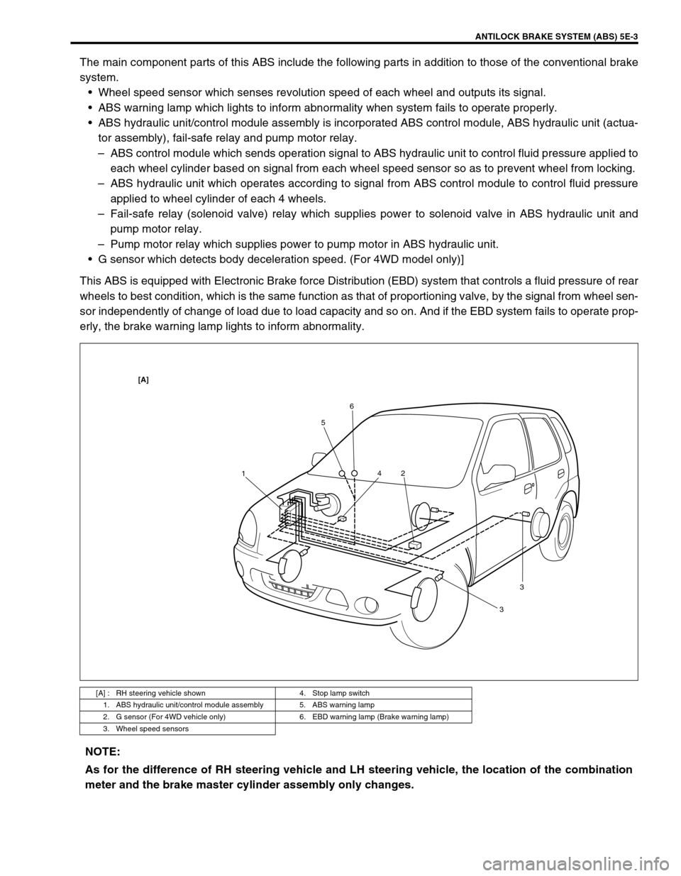
The main component parts of this ABS include the following parts in addition to those of the conventional brake
system.
Wheel speed sensor which senses revolution speed of each wheel and outputs its signal.
ABS warning lamp which lights to inform abnormality when system fails to operate properly.
ABS hydraulic unit/control module assembly is incorporated ABS control module, ABS hydraulic unit (actua-
tor assembly), fail-safe relay and pump motor relay.
–ABS control module which sends operation signal to ABS hydraulic unit to control fluid pressure applied to
each wheel cylinder based on signal from each wheel speed sensor so as to prevent wheel from locking.
–ABS hydraulic unit which operates according to signal from ABS control module to control fluid pressure
applied to wheel cylinder of each 4 wheels.
–Fail-safe relay (solenoid valve) relay which supplies power to solenoid valve in ABS hydraulic unit and
pump motor relay.
–Pump motor relay which supplies power to pump motor in ABS hydraulic unit.
G sensor which detects body deceleration speed. (For 4WD model only)]
This ABS is equipped with Electronic Brake force Distribution (EBD) system that controls a fluid pressure of rear
wheels to best condition, which is the same function as that of proportioning valve, by the signal from wheel sen-
sor independently of change of load due to load capacity and so on. And if the EBD system fails to operate prop-
erly, the brake warning lamp lights to inform abnormality.
[A] : RH steering vehicle shown 4. Stop lamp switch
1. ABS hydraulic unit/control module assembly 5. ABS warning lamp
2. G sensor (For 4WD vehicle only) 6. EBD warning lamp (Brake warning lamp)
3. Wheel speed sensors
156
2 4
33
[A]
NOTE:
As for the difference of RH steering vehicle and LH steering vehicle, the location of the combination
meter and the brake master cylinder assembly only changes.
Page 329 of 698

5E-4 ANTILOCK BRAKE SYSTEM (ABS)
SYSTEM SCHEMATIC
1. ABS hydraulic unit/control module assembly 7.“ABS” warning lamp 13. Wheel speed sensor (Right-front)
2. ABS control module 8.“EBD” warning lamp (Brake warning lamp) 14. Wheel speed sensor (Left-front)
3. ABS hydraulic unit 9. Lamp driver module 15. Wheel speed sensor (Right-rear)
4. Fail safe relay 10. ECM 16. Wheel speed sensor (Left-rear)
5. Pump motor relay 11. Data link connector 17. G sensor (For 4WD vehicle only)
6. Stop lamp switch 12. Monitor coupler
INPUT OUTPUT
ABS control
module Wheel speed sensor (LF)
Wheel speed sensor (LR)
Wheel speed sensor (RF)
Wheel speed sensor (RR)
Stop lamp switch
Diag. switch terminal
Battery Voltage
G sensor (for 4WD vehicle only)
Pump motor
relay
Fail-safe
relay
Hydraulic unit
Pump motor
LF inlet solenoid
LF outlet solenoid
LR inlet solenoid
LR outlet solenoid
RF inlet solenoid
RF outlet solenoid
RR inlet solenoid
RR outlet solenoid
“ABS” warning lamp
ECM
EBD warning lamp
(Brake warning lamp)
Data link connector
ABS hydraulic unit/control
module assembly
Page 330 of 698

ANTILOCK BRAKE SYSTEM (ABS) 5E-5
ABS HYDRAULIC UNIT/CONTROL MODULE
ASSEMBLY
ABS control module is a component of ABS hydraulic unit/control
module assembly and has the following functions.
SELF-DIAGNOSIS FUNCTION
ABS control module diagnoses conditions of the system compo-
nent parts (whether or not there is any abnormality) all the time
and indicates the results (warning of abnormality occurrence and
DTC) through the ABS warning lamp as described below.
1) When ignition switch is turned ON, ABS warning lamp lights
for 2 seconds to check its bulb and circuit.
2) When no abnormality has been detected (the system is in
good condition), ABS warning lamp turns OFF after 2 sec-
onds.
3) When an abnormality in the system is detected, ABS warn-
ing lamp lights and the area where that abnormality lies is
stored in the memory of EEPROM in ABS control module.
4) When Diag. switch terminal (2) of diagnosis connector (1)
(monitor connector) is grounded, the abnormal area is output
as DTC. It is indicated by flashing of ABS warning lamp.
(Refer to the table below.)
5) For procedure to clear all DTC’s, refer to “DIAGNOSTIC
TROUBLE CODE CLEARANCE” in this section.
Also ABS control module turns ON EBD warning lamp (brake
warning lamp) depending on the trouble that detected by the
module and EBD warning lamp does not indicate DTC as well as
ABS warning lamp.
FAIL-SAFE FUNCTION
When an abnormality occurs (an abnormal DTC is detected),
ABS control module turns OFF the fail-safe relay which supplies
power to ABS hydraulic unit. Thus, with ABS not operating,
brakes function just like the brake system of the vehicle without
ABS.
SYSTEM CONDITIONABS WARNING LAMP
Diag. switch
terminal is
not groundedDiag. switch
terminal is
grounded
In good
condition
at presentNo trouble in the past OFF DTC 12
Trouble occurred in
the pastOFF History DTC
Abnormal-
ity exists
at presentNo trouble in the past ON Current DTC
Trouble occurred in
the pastONCurrent and
history DTCs
3. Ground terminal
4. Service wire
3 11
2
4
Page 332 of 698

ANTILOCK BRAKE SYSTEM (ABS) 5E-7
1. Battery 9. ABS hydraulic unit/control module assembly 17. Left-rear wheel speed sensor
2. Main fuses 10. Terminal arrangement of connector E19 for ABS
hydraulic unit/control module assembly18. Right-front wheel speed sensor
3. Ignition switch 11. ABS fail-safe relay (Solenoid valve relay) 19. Left-front wheel speed sensor
4. Circuit fuses 12. ABS pump motor relay 20. Data link connector
5. Combination meter 13. Pump motor 21. To ECM, SDM and EPS controller (if equipped)
6. ABS warning lamp 14. Solenoid valves 22. Stop lamp
7. Brake warning lamp (“EBD” warning lamp) 15. Diagnosis monitor coupler 23. Stop lamp switch
8. Warning lamp driver module (for ABS) 16. Right-rear wheel speed sensor 24. G sensor (For 4WD vehicle only)
Wire color
BLK : Black LT GRN/BLK : Light Green/Black RED/BLU : Red/Blue
BLK/ORN : Black/Orange LT GRN/RED : Light Green/Red WHT : White
BLK/YEL : Black/Yellow ORN : Orange WHT/BLK : White/Black
BLU : Blue PNK : Pink WHT/BLU : White/Blue
BRN : Brown PNK/BLU Pink/Blue WHT/RED : White/Red
GRN : Green RED : Red YEL : Yellow
GRN/ORN : Green/Orange RED/BLK : Red/Black
TERMINAL CIRCUIT
E191–
2 Stop lamp switch
3 Right-front wheel speed sensor (+)
4 Right-front wheel speed sensor (–)
5–
6 Right-rear wheel speed sensor (–)
7 Right-rear wheel speed sensor (+)
8–
9–
10 Brake warning lamp (EBD warning lamp)
11 G sensor (For 4WD vehicle only)
12 Diagnosis switch terminal
13 Ground (For G sensor) (For 4WD vehicle only)
14 ABS warning lamp
15 Left-front wheel speed sensor (+)
16 Left-front wheel speed sensor (–)
17–
18 Ignition switch
19 Left-rear wheel speed sensor (+)
20 Left-rear wheel speed sensor (–)
21 Data link connector
22 Ground (for ABS pump motor)
23 ABS pump motor relay
24 Ground (for ABS control module)
25 ABS fail-safe relay