2000 SUZUKI SWIFT warning
[x] Cancel search: warningPage 184 of 698

STEERING WHEEL AND COLUMN 3C-11
REMOVAL
1) Disconnect negative cable at battery.
2) Disable air bag system. Refer to “DISABLING AIR BAG
SYSTEM” under “SERVICE PRECAUTIONS” in Section
10B.
3) If it is necessary to remove steering wheel and contact coil
and combination switch assembly, remove them, referring to
“STEERING WHEEL” and “CONTACT COIL AND COMBI-
NATION SWITCH ASSEMBLY”.
If it is not necessary to remove steering wheel and contact
coil and combination switch assembly, perform the following
procedure.
a) Turn steering wheel so that vehicle’s front tires are at
straight-ahead position.
b) Turn ignition switch to “LOCK” position and remove key.
4) Remove steering column hole cover (1).
5) Loosen steering column mounting nuts (“A”, “B”). WARNING:
Never rest a steering column assembly on the steering
wheel with the air bag (inflator) module face down and
column vertical. Otherwise, personal injury may result.
1
Page 200 of 698

FRONT SUSPENSION 3D-7
5) Remove strut support nuts (1).
6) Remove strut assembly.
DISASSEMBLY
1) Using a spring compressor (1), compress the strut spring (2)
till its force pressing the spring seat (3) is released.
2) Remove strut nut with special tools while coil spring is com-
pressed.
Special tool
(A) : 09900-00411
(B) : 09900-00414
(C) : 09945-26010
3) Disassemble strut assembly.
ASSEMBLY
For assembly, reverse disassembly procedure, noting the follow-
ing instructions.
Mate spring end with stepped part (3) of spring lower seat (2)
as shown.
Install spring upper seat (1), mating stepped part (4) of seat
with spring upper end (5) as shown. NOTE:
Hold strut by hand so that it will not fall off.
WARNING:
Use a commercially available spring compressor (1) and
follow the operation procedure described in the Instruc-
tion Manual supplied with that spring compressor (1).
Page 217 of 698

3E-4 REAR SUSPENSION
DIAGNOSIS
REAR SHOCK ABSORBER CHECK
Inspect for deformation or damage.
Inspect bushings for wear or damage.
Inspect for evidence of oil leakage.
Replace any defective part.
TRAILING ARM, LATERAL ROD, REAR AXLE,
PEAR AXLE HOUSING AND COIL SPRING
CHECK
Inspect for cracks, deformation or damage.
Inspect bushing for damage, wear or breakage.
Replace any defective part.WARNING:
When handling rear shock absorber (1) in which high-
pressure gas is sealed, make sure to observe the follow-
ing precautions.
Don’t disassemble it.
Don’t put it into the fire.
Don’t store it where it gets hot.
Before disposing it, be sure to drill a hole (approxi-
mately 3 mm (0.12 in.) diameter) (2) in it where shown
by an arrow in figure and let gas and oil out.
Lay it down sideways for this work. The gas itself is
harmless but it may issue out of the hole together with
chips generated by the drill. Therefore, be sure to wear
goggle.
Page 247 of 698

3F-2 WHEELS AND TIRES
GENERAL DESCRIPTION
TIRES
This vehicle is equipped with the following tire.
Tire size
: 165/70R14
The tire is of tubeless type. The tire is designed to operate satisfactorily with loads up to the full rated load
capacity when inflated to the recommended inflation pressures.
Correct tire pressures and driving habits have an important influence on tire life. Heavy cornering, excessively
rapid acceleration, and unnecessary sharp braking increase tire wear.
WHEELS
Standard equipment wheels are the following steel wheel.
Wheel size
: 14 x 4 1/2 J
REPLACEMENT TIRES
When replacement is necessary, the original equipment type tire should be used. Refer to the “Tire Placard”.
Replacement tires should be of the same size, load range and construction as those originally on the vehicle.
Use of any other size or type tire may affect ride, handling, speedometer/odometer calibration, vehicle ground
clearance and tire or snow chain clearance to the body and chassis.
It is recommended that new tires be installed in pairs on the same axle. If necessary to replace only one tire, it
should be paired with the tire having the most tread, to equalize braking traction.
The metric term for tire inflation pressure is the kilo pascal (kPa).
Tire pressures is usually printed in both kPa and psi on the “Tire
Placard”.
Metric tire gauges are available from tool suppliers.
The chart, shown the table, converts commonly used inflation
pressures from kPa to psi.
REPLACEMENT WHEELS
Wheels must be replaced if they are bent, dented, have excessive lateral or radial runout, air leak through
welds, have elongated bolt holes, if lug nuts won’t stay tight, or if they are heavily rusted. Wheels with greater
runout than shown in figure below may cause objectional vibrations.
Replacement wheels must be equivalent to the original equipment wheels in load capacity, diameter, rim with
offset and mounting configuration. A wheel of improper size or type may affect wheel and bearing life, brake
cooling, speedometer/odometer calibration, vehicle ground clearance and tire clearance to body and chassis.WARNING:
Do not mix different types of tires on the same vehicle such as radial, bias and bias-belted tires except
in emergencies, because handling may be seriously affected and may result in loss of control.
kPa kgf/cm²pis
160 1.6 23
180 1.8 26
200 2.0 29
220 2.2 32
240 2.4 35
260 2.6 38
280 2.8 41
300 3.0 44
Page 249 of 698

3F-4 WHEELS AND TIRES
Dynamic balance, as shown in left figure, is the equal distribution
of weight on each side of the wheel centerline so that when the
tire spins there is no tendency for the assembly to move from side
to side. Wheels that are dynamically unbalanced may cause
shimmy.
GENERAL BALANCE PROCEDURES
Deposits of mud, etc. must be cleaned from inside of rim.
Each tire should be inspected for any damage, then balanced according to equipment manufacturer’s recom-
mendation.
OFF-VEHICLE BALANCING
Most electronic off-vehicle balancers are more accurate than the on-vehicle spin balancers. They are easy to
use and give a dynamic (two plane) balance. Although they do not correct for drum or disc unbalance as does
on-vehicle spin balancing, this is overcome by their accuracy, usually to within 1/8 ounce.
ON-VEHICLE BALANCING
On-vehicle balancing methods vary with equipment and tool manufacturers. Be sure to follow each manufac-
turer’s instructions during balancing operation.
1. Heavy spot wheel shimmy [C] : Before correction
2. Balance weights addition point [D] : Corrective weights
3. C/L of spindle
WARNING:
Stones should be removed from the tread in order to avoid operator injury during spin balancing and
to obtain good balance.
WARNING:
Wheel spin should be limited to 35 mph (55 km/h) as indicated on speedometer.
This limit is necessary because speedometer only indicates one-half of actual wheel speed when one
drive wheel is spinning and the other drive wheel is stopped.
Unless care is taken in limiting drive wheel spin, spinning wheel can reach excessive speeds. This
can result in possible tire disintegration or differential failure, which could cause serious personal
injury or extensive vehicle damage.
CAUTION:
For vehicle equipped with ABS, using on-vehicle balancing method with ignition switch ON may set
malfunction diagnostic trouble code (DTC) of ABS even when system is in good condition.
Never turn ignition switch ON while spinning wheel.
Page 253 of 698

3F-8 WHEELS AND TIRES
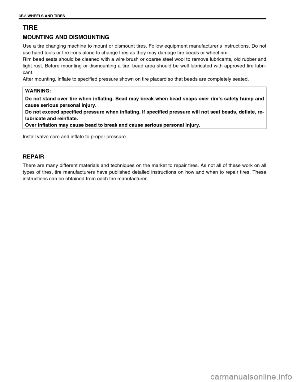
TIRE
MOUNTING AND DISMOUNTING
Use a tire changing machine to mount or dismount tires. Follow equipment manufacturer’s instructions. Do not
use hand tools or tire irons alone to change tires as they may damage tire beads or wheel rim.
Rim bead seats should be cleaned with a wire brush or coarse steel wool to remove lubricants, old rubber and
light rust. Before mounting or dismounting a tire, bead area should be well lubricated with approved tire lubri-
cant.
After mounting, inflate to specified pressure shown on tire placard so that beads are completely seated.
Install valve core and inflate to proper pressure.
REPAIR
There are many different materials and techniques on the market to repair tires. As not all of these work on all
types of tires, tire manufacturers have published detailed instructions on how and when to repair tires. These
instructions can be obtained from each tire manufacturer.WARNING:
Do not stand over tire when inflating. Bead may break when bead snaps over rim’s safety hump and
cause serious personal injury.
Do not exceed specified pressure when inflating. If specified pressure will not seat beads, deflate, re-
lubricate and reinflate.
Over inflation may cause bead to break and cause serious personal injury.
Page 279 of 698

5-6 BRAKES
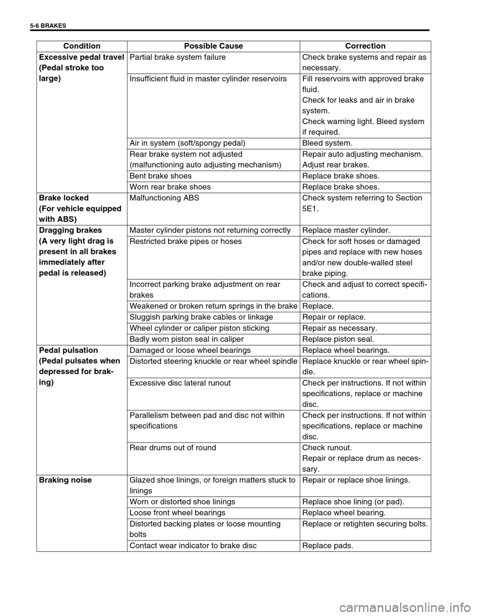
Excessive pedal travel
(Pedal stroke too
large)Partial brake system failure Check brake systems and repair as
necessary.
Insufficient fluid in master cylinder reservoirs Fill reservoirs with approved brake
fluid.
Check for leaks and air in brake
system.
Check warning light. Bleed system
if required.
Air in system (soft/spongy pedal) Bleed system.
Rear brake system not adjusted
(malfunctioning auto adjusting mechanism)Repair auto adjusting mechanism.
Adjust rear brakes.
Bent brake shoes Replace brake shoes.
Worn rear brake shoes Replace brake shoes.
Brake locked
(For vehicle equipped
with ABS)Malfunctioning ABS Check system referring to Section
5E1.
Dragging brakes
(A very light drag is
present in all brakes
immediately after
pedal is released)Master cylinder pistons not returning correctly Replace master cylinder.
Restricted brake pipes or hoses Check for soft hoses or damaged
pipes and replace with new hoses
and/or new double-walled steel
brake piping.
Incorrect parking brake adjustment on rear
brakesCheck and adjust to correct specifi-
cations.
Weakened or broken return springs in the brake Replace.
Sluggish parking brake cables or linkage Repair or replace.
Wheel cylinder or caliper piston sticking Repair as necessary.
Badly worn piston seal in caliper Replace piston seal.
Pedal pulsation
(Pedal pulsates when
depressed for brak-
ing)Damaged or loose wheel bearings Replace wheel bearings.
Distorted steering knuckle or rear wheel spindle Replace knuckle or rear wheel spin-
dle.
Excessive disc lateral runout Check per instructions. If not within
specifications, replace or machine
disc.
Parallelism between pad and disc not within
specificationsCheck per instructions. If not within
specifications, replace or machine
disc.
Rear drums out of round Check runout.
Repair or replace drum as neces-
sary.
Braking noise
Glazed shoe linings, or foreign matters stuck to
liningsRepair or replace shoe linings.
Worn or distorted shoe linings Replace shoe lining (or pad).
Loose front wheel bearings Replace wheel bearing.
Distorted backing plates or loose mounting
boltsReplace or retighten securing bolts.
Contact wear indicator to brake disc Replace pads. Condition Possible Cause Correction
Page 280 of 698

BRAKES 5-7
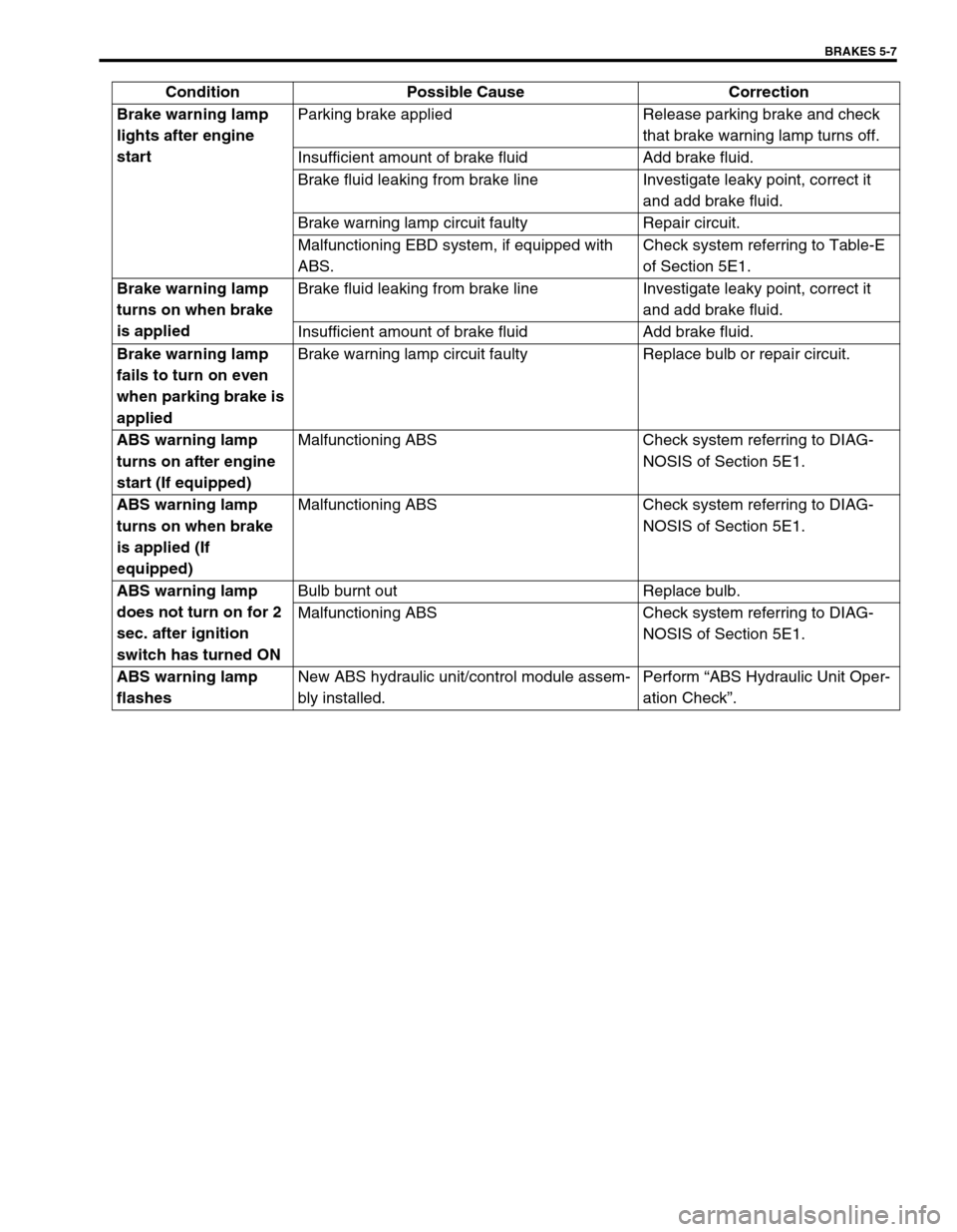
Brake warning lamp
lights after engine
startParking brake applied Release parking brake and check
that brake warning lamp turns off.
Insufficient amount of brake fluid Add brake fluid.
Brake fluid leaking from brake line Investigate leaky point, correct it
and add brake fluid.
Brake warning lamp circuit faulty Repair circuit.
Malfunctioning EBD system, if equipped with
ABS.Check system referring to Table-E
of Section 5E1.
Brake warning lamp
turns on when brake
is appliedBrake fluid leaking from brake line Investigate leaky point, correct it
and add brake fluid.
Insufficient amount of brake fluid Add brake fluid.
Brake warning lamp
fails to turn on even
when parking brake is
appliedBrake warning lamp circuit faulty Replace bulb or repair circuit.
ABS warning lamp
turns on after engine
start (If equipped)Malfunctioning ABS Check system referring to DIAG-
NOSIS of Section 5E1.
ABS warning lamp
turns on when brake
is applied (If
equipped)Malfunctioning ABS Check system referring to DIAG-
NOSIS of Section 5E1.
ABS warning lamp
does not turn on for 2
sec. after ignition
switch has turned ONBulb burnt out Replace bulb.
Malfunctioning ABS Check system referring to DIAG-
NOSIS of Section 5E1.
ABS warning lamp
flashesNew ABS hydraulic unit/control module assem-
bly installed.Perform “ABS Hydraulic Unit Oper-
ation Check”. Condition Possible Cause Correction