2000 SUZUKI SWIFT warning
[x] Cancel search: warningPage 24 of 698

GENERAL INFORMATION 0A-21
WHEN USING FLOOR JACK
In raising front or rear vehicle end off the floor by jacking, be sure
to put the jack against the front jacking bracket (1), the center por-
tion of rear axle (2) (2WD vehicle) or rear axle housing (3) (4WD
vehicle).
To perform service with either front or rear vehicle end jacked up,
be sure to place safety stands (1) under vehicle body so that vehi-
cle body is securely supported. And then check to ensure that
vehicle body does not slide on safety stands (1) and the vehicle is
held stable for safety’s sake. WARNING:
If the vehicle to be jacked up only at the front or rear end,
be sure to block the wheels on ground in order to ensure
safety.
After the vehicle is jacked up, be sure to support it on
stands. It is extremely dangerous to do any work on the
vehicle raised on jack alone.
CAUTION:
Never apply jack against suspension parts (i.e., stabi-
lizer, etc) or vehicle floor, or it may get deformed.
[A] : Front
[B] : Rear
2. Embossed mark
Page 30 of 698

MAINTENANCE AND LUBRICATION 0B-1
0A 6F1
0B
0B
6G
1A 6H
1B 6K
37A
3A 7A1
3B1 7B1
3C1 7C1
3D 7D
3E 7E
3F 7F
4A2 8A
4B 8B
8C
58D
5A 8E
5B
5C 9
5E
5E1 10
10A
610B
6-1
6A1
6A2
6A4
6B
6C
6E1
6E2
SECTION 0B
MAINTENANCE AND LUBRICATION
CONTENTS
MAINTENANCE SCHEDULE .......................... 0B-2
MAINTENANCE SCHEDULE UNDER
NORMAL DRIVING CONDITIONS .............. 0B-2
MAINTENANCE RECOMMENDED UNDER
SEVERE DRIVING CONDITIONS ............... 0B-4
MAINTENANCE SERVICE .............................. 0B-5
ENGINE ....................................................... 0B-5
DRIVE BELT ............................................ 0B-5
VALVE LASH (CLEARANCE) .................. 0B-6
ENGINE OIL AND OIL FILTER ................ 0B-6
ENGINE COOLANT ................................. 0B-8
EXHAUST SYSTEM............................... 0B-10
IGNITION SYSTEM ................................... 0B-10
SPARK PLUGS ...................................... 0B-10
FUEL SYSTEM .......................................... 0B-10
AIR CLEANER FILTER .......................... 0B-10
FUEL LINES AND CONNECTIONS....... 0B-11
FUEL FILTER ......................................... 0B-11
FUEL TANK............................................ 0B-12
EMISSION CONTROL SYSTEM ............... 0B-12
PCV VALVE ........................................... 0B-12
FUEL EVAPORATIVE EMISSION
CONTROL SYSTEM .............................. 0B-12BRAKE ....................................................... 0B-12
BRAKE DISCS AND PADS (FRONT) .... 0B-12
BRAKE DRUMS AND SHOES
(REAR) ................................................... 0B-13
BRAKE HOSES AND PIPES ................. 0B-13
BRAKE FLUID........................................ 0B-13
BRAKE LEVER AND CABLE ................. 0B-13
CHASSIS AND BODY ............................... 0B-14
CLUTCH................................................. 0B-14
TIRES / WHEELS .................................. 0B-14
SUSPENSION SYSTEM ........................ 0B-15
STEERING SYSTEM ............................. 0B-15
DRIVE SHAFT (AXLE) BOOTS /
PROPELLER SHAFTS (4WD) ............... 0B-16
MANUAL TRANSMISSION OIL ............. 0B-17
AUTOMATIC TRANSMISSION FLUID .. 0B-17
TRANSFER OIL (4WD) AND REAR
DIFFERENTIAL OIL (4WD) ................... 0B-18
ALL LATCHES, HINGES AND
LOCKS ................................................... 0B-19
FINAL INSPECTION ..................................... 0B-19
RECOMMENDED FLUIDS AND
LUBRICANTS................................................ 0B-21
WARNING:
For vehicles equipped with Supplemental Restraint (Air Bag) System:
Service on and around the air bag system components or wiring must be performed only by an
authorized SUZUKI dealer. Refer to “Air Bag System Components and Wiring Location View” under
“General Description” in air bag system section in order to confirm whether you are performing ser-
vice on or near the air bag system components or wiring. Please observe all WARNINGS and “Ser-
vice Precautions” under “On-Vehicle Service” in air bag system section before performing service
on or around the air bag system components or wiring. Failure to follow WARNINGS could result in
unintentional activation of the system or could render the system inoperative. Either of these two
conditions may result in severe injury.
Technical service work must be started at least 90 seconds after the ignition switch is turned to the
“LOCK” position and the negative cable is disconnected from the battery. Otherwise, the system
may be activated by reserve energy in the Sensing and Diagnostic Module (SDM).
Page 34 of 698
MAINTENANCE AND LUBRICATION 0B-5
MAINTENANCE SERVICE
ENGINE
DRIVE BELT
WATER PUMP AND GENERATOR DRIVE BELT INSPEC-
TION
1) Disconnect negative (–) cable at battery.
2) Inspect belt for cracks, cuts, deformation, wear and cleanli-
ness. If any defect exists, replace.
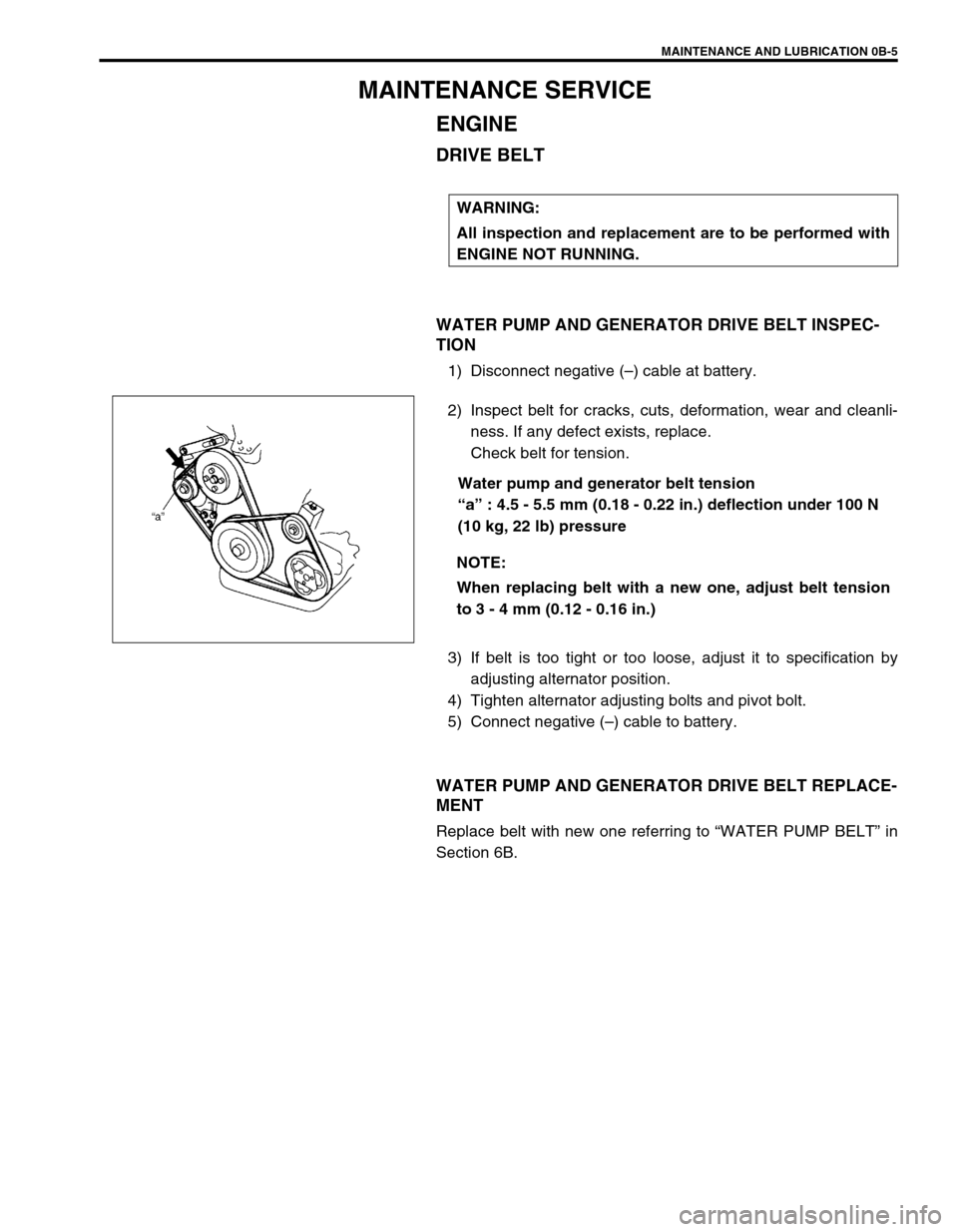
Check belt for tension.
Water pump and generator belt tension
“a” : 4.5 - 5.5 mm (0.18 - 0.22 in.) deflection under 100 N
(10 kg, 22 lb) pressure
3) If belt is too tight or too loose, adjust it to specification by
adjusting alternator position.
4) Tighten alternator adjusting bolts and pivot bolt.
5) Connect negative (–) cable to battery.
WATER PUMP AND GENERATOR DRIVE BELT REPLACE-
MENT
Replace belt with new one referring to “WATER PUMP BELT” in
Section 6B.WARNING:
All inspection and replacement are to be performed with
ENGINE NOT RUNNING.
NOTE:
When replacing belt with a new one, adjust belt tension
to 3 - 4 mm (0.12 - 0.16 in.)
Page 35 of 698
0B-6 MAINTENANCE AND LUBRICATION
A/C COMPRESSOR DRIVE BELT (IF EQUIPPED) INSPEC-
TION
1) Disconnect negative (–) cable at battery.
2) Inspect belt for cracks, cuts, deformation, wear and cleanli-
ness. If any defect exists, replace.
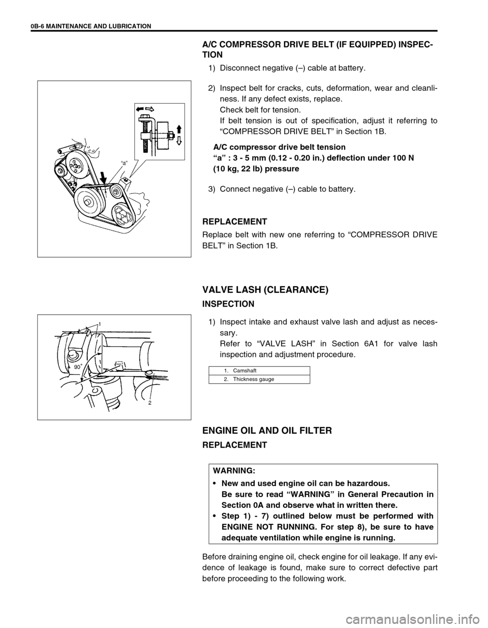
Check belt for tension.
If belt tension is out of specification, adjust it referring to
“COMPRESSOR DRIVE BELT” in Section 1B.
A/C compressor drive belt tension
“a” : 3 - 5 mm (0.12 - 0.20 in.) deflection under 100 N
(10 kg, 22 lb) pressure
3) Connect negative (–) cable to battery.
REPLACEMENT
Replace belt with new one referring to “COMPRESSOR DRIVE
BELT” in Section 1B.
VALVE LASH (CLEARANCE)
INSPECTION
1) Inspect intake and exhaust valve lash and adjust as neces-
sary.
Refer to “VALVE LASH” in Section 6A1 for valve lash
inspection and adjustment procedure.
ENGINE OIL AND OIL FILTER
REPLACEMENT
Before draining engine oil, check engine for oil leakage. If any evi-
dence of leakage is found, make sure to correct defective part
before proceeding to the following work.
1. Camshaft
2. Thickness gauge
WARNING:
New and used engine oil can be hazardous.
Be sure to read “WARNING” in General Precaution in
Section 0A and observe what in written there.
Step 1) - 7) outlined below must be performed with
ENGINE NOT RUNNING. For step 8), be sure to have
adequate ventilation while engine is running.
Page 37 of 698
0B-8 MAINTENANCE AND LUBRICATION
6) Replenish oil until oil level is brought to FULL level mark on
dipstick. (oil pan and oil filter capacity). The filler inlet is at
the top of the cylinder head cover.
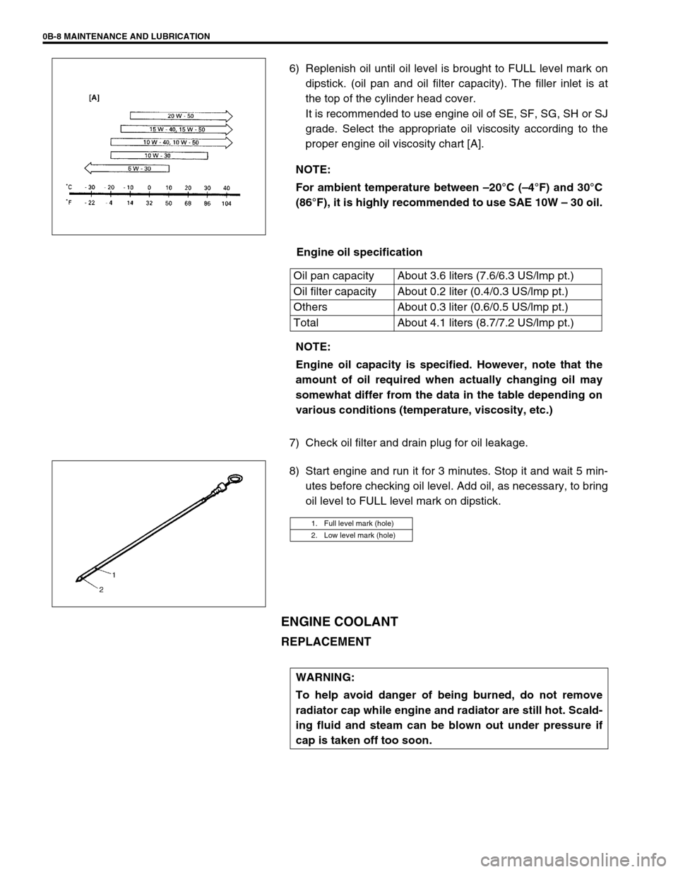
It is recommended to use engine oil of SE, SF, SG, SH or SJ
grade. Select the appropriate oil viscosity according to the
proper engine oil viscosity chart [A].
Engine oil specification
7) Check oil filter and drain plug for oil leakage.
8) Start engine and run it for 3 minutes. Stop it and wait 5 min-
utes before checking oil level. Add oil, as necessary, to bring
oil level to FULL level mark on dipstick.
ENGINE COOLANT
REPLACEMENT
NOTE:
For ambient temperature between –20°C (–4°F) and 30°C
(86°F), it is highly recommended to use SAE 10W – 30 oil.
Oil pan capacity About 3.6 liters (7.6/6.3 US/lmp pt.)
Oil filter capacity About 0.2 liter (0.4/0.3 US/lmp pt.)
Others About 0.3 liter (0.6/0.5 US/lmp pt.)
Total About 4.1 liters (8.7/7.2 US/lmp pt.)
NOTE:
Engine oil capacity is specified. However, note that the
amount of oil required when actually changing oil may
somewhat differ from the data in the table depending on
various conditions (temperature, viscosity, etc.)
1. Full level mark (hole)
2. Low level mark (hole)
WARNING:
To help avoid danger of being burned, do not remove
radiator cap while engine and radiator are still hot. Scald-
ing fluid and steam can be blown out under pressure if
cap is taken off too soon.
Page 39 of 698
0B-10 MAINTENANCE AND LUBRICATION
EXHAUST SYSTEM
INSPECTION
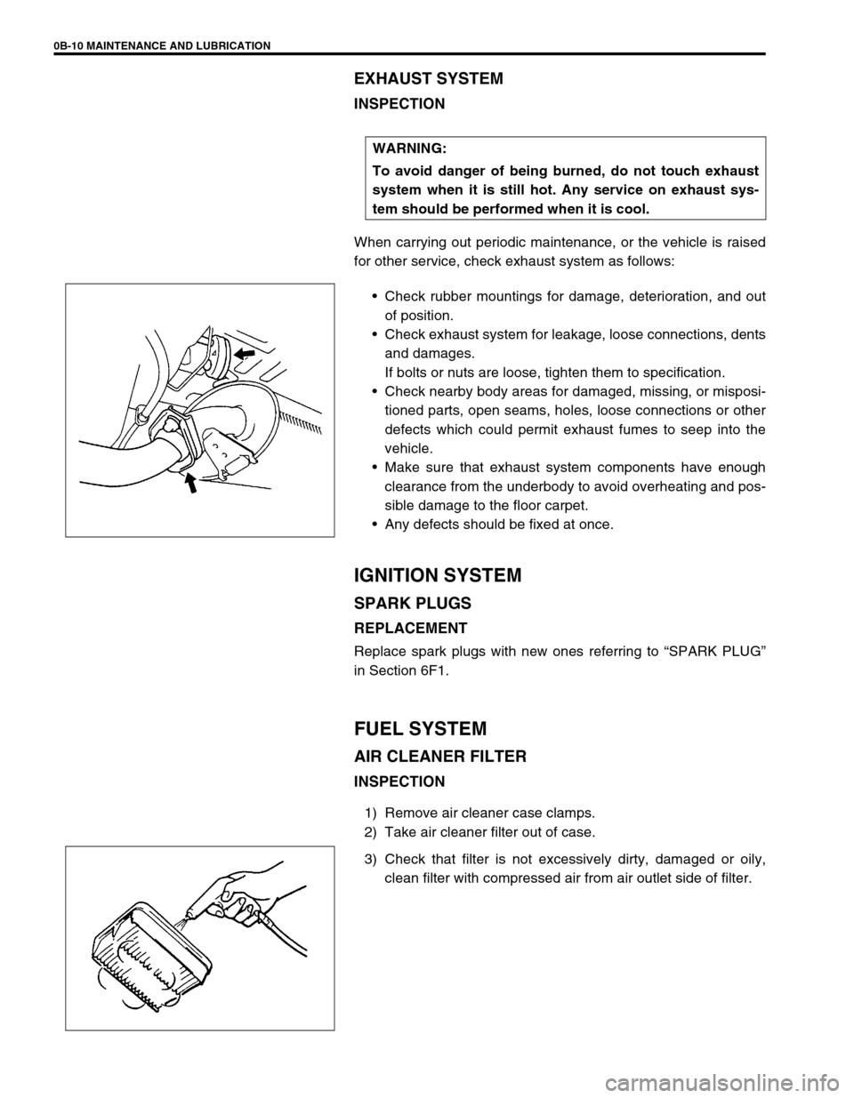
When carrying out periodic maintenance, or the vehicle is raised
for other service, check exhaust system as follows:
Check rubber mountings for damage, deterioration, and out
of position.
Check exhaust system for leakage, loose connections, dents
and damages.
If bolts or nuts are loose, tighten them to specification.
Check nearby body areas for damaged, missing, or misposi-
tioned parts, open seams, holes, loose connections or other
defects which could permit exhaust fumes to seep into the
vehicle.
Make sure that exhaust system components have enough
clearance from the underbody to avoid overheating and pos-
sible damage to the floor carpet.
Any defects should be fixed at once.
IGNITION SYSTEM
SPARK PLUGS
REPLACEMENT
Replace spark plugs with new ones referring to “SPARK PLUG”
in Section 6F1.
FUEL SYSTEM
AIR CLEANER FILTER
INSPECTION
1) Remove air cleaner case clamps.
2) Take air cleaner filter out of case.
3) Check that filter is not excessively dirty, damaged or oily,
clean filter with compressed air from air outlet side of filter. WARNING:
To avoid danger of being burned, do not touch exhaust
system when it is still hot. Any service on exhaust sys-
tem should be performed when it is cool.
Page 40 of 698

MAINTENANCE AND LUBRICATION 0B-11
4) Install air cleaner filter fitting protrusion (1) of filter into
groove (2) of case and clamp upper case securely.
REPLACEMENT
Replace air cleaner filter with new one according to steps 1), 2)
and 4) of inspection procedure.
FUEL LINES AND CONNECTIONS
INSPECTION
Visually inspect fuel lines and connections for evidence of fuel
leakage, hose cracking and damage. Make sure all clamps are
secure.
Repair leaky joints, if any.
Replace hoses that are suspected of being cracked.
FUEL FILTER
REPLACEMENT
Fuel filter (1) is installed in fuel pump assembly (2) in fuel tank.
Replace fuel filter with new one, referring to “FUEL PUMP
ASSEMBLY” in Section 6C for proper procedure.
WARNING:
This work must be performed in a well ventilated area
and away from any open flames (such as gas hot water
heaters).
Page 48 of 698
MAINTENANCE AND LUBRICATION 0B-19
ALL LATCHES, HINGES AND LOCKS
INSPECTION
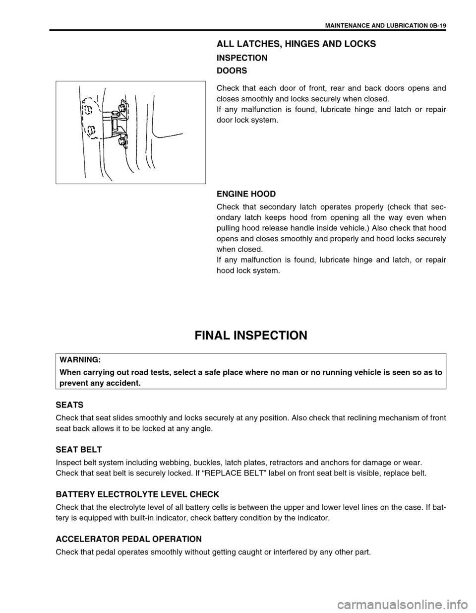
DOORS
Check that each door of front, rear and back doors opens and
closes smoothly and locks securely when closed.
If any malfunction is found, lubricate hinge and latch or repair
door lock system.
ENGINE HOOD
Check that secondary latch operates properly (check that sec-
ondary latch keeps hood from opening all the way even when
pulling hood release handle inside vehicle.) Also check that hood
opens and closes smoothly and properly and hood locks securely
when closed.
If any malfunction is found, lubricate hinge and latch, or repair
hood lock system.
FINAL INSPECTION
SEATS
Check that seat slides smoothly and locks securely at any position. Also check that reclining mechanism of front
seat back allows it to be locked at any angle.
SEAT BELT
Inspect belt system including webbing, buckles, latch plates, retractors and anchors for damage or wear.
Check that seat belt is securely locked. If “REPLACE BELT” label on front seat belt is visible, replace belt.
BATTERY ELECTROLYTE LEVEL CHECK
Check that the electrolyte level of all battery cells is between the upper and lower level lines on the case. If bat-
tery is equipped with built-in indicator, check battery condition by the indicator.
ACCELERATOR PEDAL OPERATION
Check that pedal operates smoothly without getting caught or interfered by any other part.
WARNING:
When carrying out road tests, select a safe place where no man or no running vehicle is seen so as to
prevent any accident.