2000 SUZUKI SWIFT service
[x] Cancel search: servicePage 119 of 698

3A-2 FRONT END ALIGNMENT
GENERAL DESCRIPTION
Front alignment refers to the angular relationship between the
front wheels, the front suspension attaching parts and the ground.
Generally, the only adjustment required for front alignment is toe
setting.
Camber and caster can’t be adjusted. Therefore, should camber
or caster be out of specification due to the damage caused by
hazardous road conditions or collision, whether the damage is in
body or in suspension should be determined. If the body is dam-
aged, it should be repaired and if suspension is damaged, it
should be replaced.
TOE SETTING
Toe is the turning in or out of the front wheels. The purpose of a
toe specification is to ensure parallel rolling of the front wheels
(Excessive toe-in or toe-out may increase tire wear).
Toe-in
“B”-“A” : 0 ± 1 mm (0 ± 0.039 in.)
For adjusting toe setting, refer to “TOE ADJUSTMENT” in this
section.
CAMBER
Camber is the tilting of the front wheels from the vertical, as
viewed from the front of the vehicle. When the wheels tilt outward
at the top, the camber is positive. When the wheels tilt inward at
the top, the camber is negative. The amount of tilt is measured in
degrees.
Camber “C”
2WD vehicle : –0° 20’ ± 1°
4WD vehicle : 0° ± 1°
ALIGNMENT SERVICE DATA (REFERENCE)
Caster
2WD vehicle : 3° 25’ ± 2°
4WD vehicle : 3° 35’ ± 2°
Kingpin inclination
2WD vehicle : 12° 40’ ± 2°
4WD vehicle : 12° 15’ ± 2° NOTE:
Toe-in value was measured by using a toe-in gauge.
[A]: Wheel top view
1. Forward
“A”
“B”1 [A]
1. Body center [A]: Front view
2. Center line of wheel
2
1
90
o
C [A]
Page 122 of 698

MANUAL RACK AND PINION 3B-1
6F1
6F2
6G
6H
7A
3B
7C1
7D
7E
7F
8A
8B
8C
8D
8E
9
10
10A
10B
SECTION 3B
MANUAL RACK AND PINION
CONTENTS
GENERAL DESCRIPTION .............................. 3B-2
DIAGNOSIS ..................................................... 3B-3
ON-VEHICLE SERVICE .................................. 3B-4
LUBRICATION ............................................. 3B-4
TIE ROD END .............................................. 3B-6
MANUAL RACK AND PINION ASSEMBLY
(STEERING GEAR CASE) .......................... 3B-7
RACK BOOT/TIE ROD .............................. 3B-10STEERING RACK PLUNGER ................... 3B-12
STEERING PINION ................................... 3B-14
STEERING RACK...................................... 3B-15
PINION BEARING ..................................... 3B-17
RACK BUSHING ........................................ 3B-18
REQUIRED SERVICE MATERIAL................ 3B-19
SPECIAL TOOL ............................................ 3B-20
WARNING:
For vehicles equipped with a Air Bag System
Service on or around air bag system components or wiring must be performed only by an autho-
rized suzuki dealer. Please observe all WARNINGS and CAUTIONS in SECTION 10B and Precau-
tions, Air Bag System Components and Wiring Location view in Section 10B before performing
service on or around air bag system components or wiring. Failure to follow WARNINGS could
result in unintended activation of the system or could render the system inoperative. Either of these
two conditions may result in severe injury.
Technical service work must be started at least 90 seconds after the ignition switch is turned to the
“LOCK” position and the negative cable is disconnected from the battery. Otherwise, the system
may be deployed by reserve energy in the Sensing and Diagnostic Module (SDM).
NOTE:
All steering gear fasteners are important attaching parts in that they could affect the performance of
vital parts and systems, and/or could result in major repair expense. They must be replaced with one
of the same part number or with an equivalent part if replacement becomes necessary. Do not use a
replacement part of lesser quality or substitute design. Torque values must be used as specified dur-
ing reassembly to assure proper retention of these parts.
Page 125 of 698

3B-4 MANUAL RACK AND PINION
STEERING WHEEL CHECK
Check steering wheel for play and rattle, holding vehicle in
straight forward condition on the ground.
Steering wheel play
“a” : 0 – 30 mm (0 – 1.1 in.)
If steering wheel play is not within specification, inspect as follows
and replace if found defective.
Tie-rod end ball stud for wear (ball stud should move when
more than 2 kg-cm torque is applied.)
Lower ball joint for wear
Steering shaft joint for wear
Steering pinion or rack gear for wear or breakage
Each part for looseness
ON-VEHICLE SERVICE
LUBRICATION
When inner parts of the steering gear case were disassembled, they should be washed clean before reassem-
bly. It is recommended to use the grease as given below where grease application is indicated in the text.
✱
✱✱ ✱ SUZUKI SUPER GREASE (E) 99000-25050, or Lithium grease
(applicable for –40°C ~ 130°C or 104°F ~ 266°F)
Page 140 of 698

MANUAL RACK AND PINION 3B-19
INSTALLATION
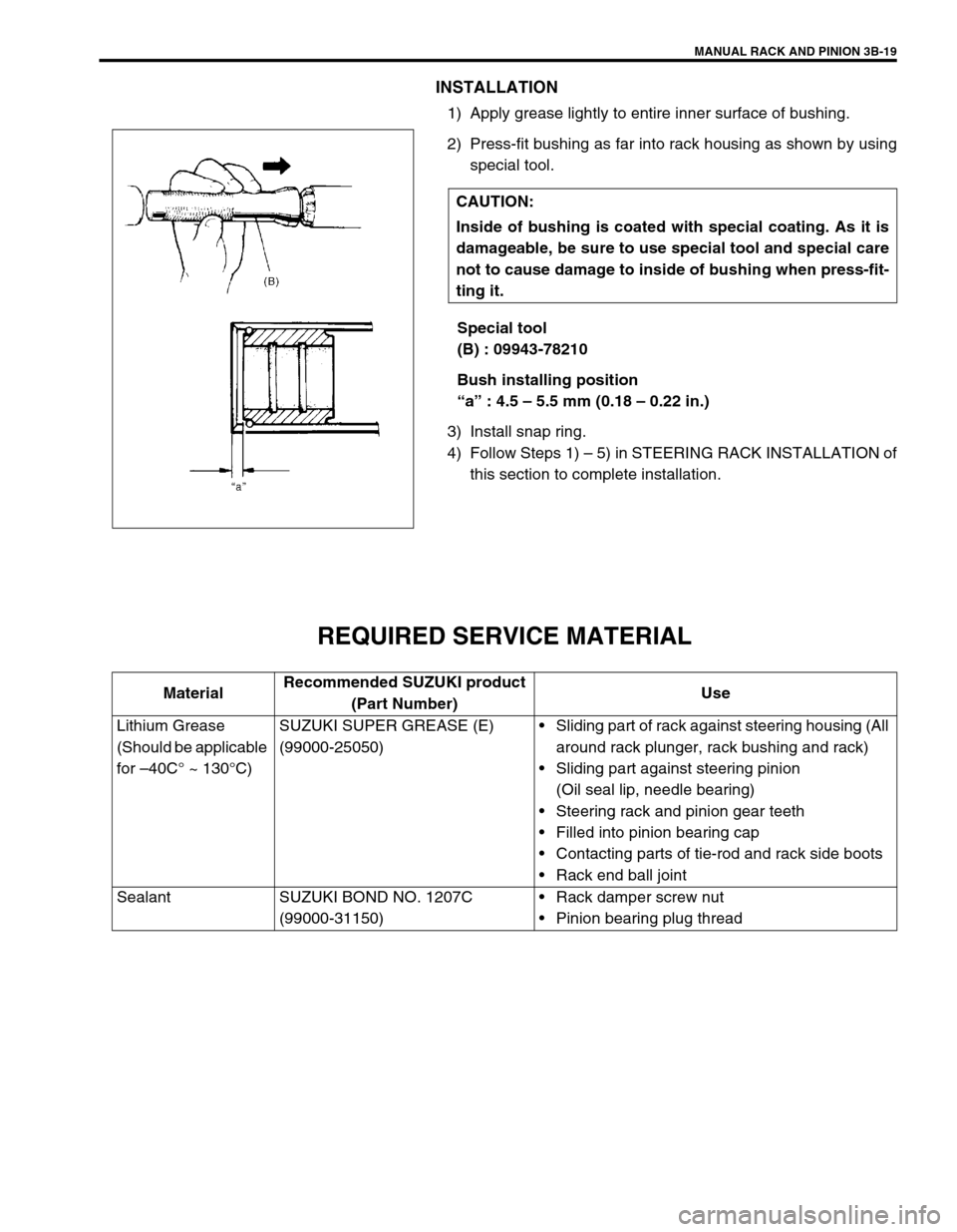
1) Apply grease lightly to entire inner surface of bushing.
2) Press-fit bushing as far into rack housing as shown by using
special tool.
Special tool
(B) : 09943-78210
Bush installing position
“a” : 4.5 – 5.5 mm (0.18 – 0.22 in.)
3) Install snap ring.
4) Follow Steps 1) – 5) in STEERING RACK INSTALLATION of
this section to complete installation.
REQUIRED SERVICE MATERIAL
CAUTION:
Inside of bushing is coated with special coating. As it is
damageable, be sure to use special tool and special care
not to cause damage to inside of bushing when press-fit-
ting it.
MaterialRecommended SUZUKI product
(Part Number)Use
Lithium Grease
(Should be applicable
for –40C° ~ 130°C)SUZUKI SUPER GREASE (E)
(99000-25050)Sliding part of rack against steering housing (All
around rack plunger, rack bushing and rack)
Sliding part against steering pinion
(Oil seal lip, needle bearing)
Steering rack and pinion gear teeth
Filled into pinion bearing cap
Contacting parts of tie-rod and rack side boots
Rack end ball joint
Sealant SUZUKI BOND NO. 1207C
(99000-31150)Rack damper screw nut
Pinion bearing plug thread
Page 142 of 698

ELECTRICAL POWER STEERING (P/S) SYSTEM 3B1-1
6F1
6F2
6G
6H
6K
7A
7A1
3B1
7D
7E
7F
8A
8B
8C
8D
8E
9
10
10A
10B
SECTION 3B1
ELECTRICAL POWER STEERING (P/S) SYSTEM
CONTENTS
GENERAL DESCRIPTION .............................3B1-2
SYSTEM COMPONENTS ........................... 3B1-2
WIRING DIAGRAM ..................................... 3B1-3
DIAGNOSIS ....................................................3B1-4
ON-BOARD DIAGNOSTIC SYSTEM .......... 3B1-4
PRECAUTIONS IN DIAGNOSING
TROUBLES ................................................. 3B1-4
SYSTEM CHECK FLOW TABLE ................ 3B1-5
MALFUNCTION INDICATOR LAMP
(“EPS” WARNING LAMP) CHECK.............. 3B1-7
DTC CHECK ............................................... 3B1-8
DTC CLEARANCE ...................................... 3B1-9
SERIAL DATA LINK CIRCUIT CHECK ..... 3B1-10
DTC TABLE .............................................. 3B1-11
TABLE A - MALFUNCTION INDICATOR
LAMP DOES NOT COME ON AT
IGNITION SWITCH ON BUT LEAVING
ENGINE OFF ............................................ 3B1-13
TABLE B - MALFUNCTION INDICATOR
LAMP FLASHES AT IGNITION SWITCH
ON ............................................................. 3B1-15
TABLE C - MALFUNCTION INDICATOR
LAMP DOES NOT FLASH, JUST
REMAINS ON OR JUST REMAINS OFF
EVEN WITH DIAGNOSIS SWITCH
TERMINAL GROUNDED .......................... 3B1-15
DTC C1111 (DTC No.11) TORQUE
SENSOR MAIN CIRCUIT FAILURE ......... 3B1-16
DTC C1113 (DTC No.13) TORQUE
SENSOR MAIN AND SUB CIRCUIT
FAILURE ................................................... 3B1-16DTC C1115 (DTC No.15) TORQUE
SENSOR SUB CIRCUIT FAILURE........... 3B1-16
DTC C1114 (DTC No.14) TORQUE
SENSOR 5V POWER SUPPLY CIRCUIT
FAILURE ................................................... 3B1-17
DTC C1116 (DTC No.16) TORQUE
SENSOR 8V POWER SUPPLY CIRCUIT
FAILURE ................................................... 3B1-18
DTC C1121/C1123/C1124
(DTC No.21/23/24) VSS CIRCUIT
FAILURE ................................................... 3B1-19
DTC C1122 (DTC No.22) ENGINE
SPEED SIGNAL CIRCUIT FAILURE ........ 3B1-20
DTC C1141/C1142/C1143/C1144/C1145
(DTC No.41/42/43/44/45) MOTOR
CIRCUIT FAILURE ................................... 3B1-21
DTC C1151 (DTC No.51) CLUTCH
CIRCUIT FAILURE ................................... 3B1-22
DTC C1153(DTC No.53) P/S CONTROL
MODULE POWER SUPPLY CIRCUIT
FAILURE ................................................... 3B1-24
DTC C1152/C1154/C1155
(DTC No.52/54/55) P/S CONTROL
MODULE FAILURE .................................. 3B1-24
TROUBLE DIAGNOSIS (FOR TROUBLE
NOT INDICATED BY ON BOARD
DIAGNOSTIC SYSTEM)........................... 3B1-25
INSPECTION OF P/S CONTROL
MODULE AND ITS CIRCUITS ................. 3B1-26
STEERING WHEEL PLAY
INSPECTION ............................................ 3B1-28 WARNING:
For vehicles equipped with Supplemental Restraint (Air Bag) System :
Service on and around the air bag system components or wiring must be performed only by an
authorized SUZUKI dealer. Refer to “Air Bag System Components and Wiring Location View” under
“General Description” in air bag system section in order to confirm whether you are performing ser-
vice on or near the air bag system components or wiring. Please observe all WARNINGS and “Ser-
vice Precautions” under “On-Vehicle Service” in air bag system section before performing service
on or around the air bag system components or wiring. Failure to follow WARNINGS could result in
unintentional activation of the system or could render the system inoperative. Either of these two
conditions may result in severe injury.
Technical service work must be started at least 90 seconds after the ignition switch is turned to the
“LOCK” position and the negative cable is disconnected from the battery. Otherwise, the system
may be activated by reserve energy in the Sensing and Diagnostic Module (SDM).
Page 143 of 698

3B1-2 ELECTRICAL POWER STEERING (P/S) SYSTEM
STEERING FORCE INSPECTION ........... 3B1-28
ON-VEHICLE SERVICE ............................... 3B1-29
P/S CONTROL MODULE ......................... 3B1-29
TORQUE SENSOR .................................. 3B1-29MOTOR AND CLUTCH ............................ 3B1-30
STEERING COLUMN ASSEMBLY .......... 3B1-31
SPECIAL TOOL ........................................... 3B1-31
GENERAL DESCRIPTION
SYSTEM COMPONENTS
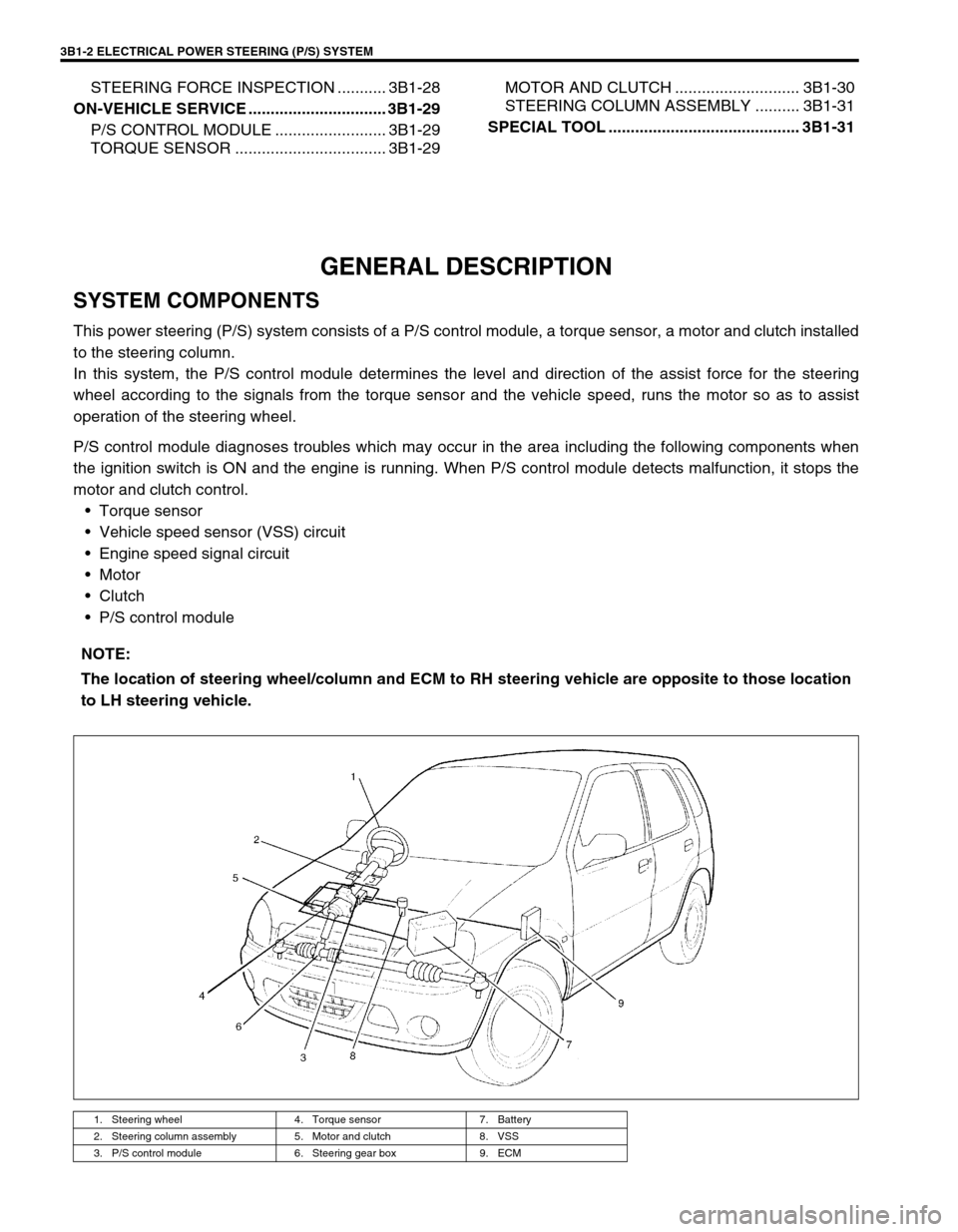
This power steering (P/S) system consists of a P/S control module, a torque sensor, a motor and clutch installed
to the steering column.
In this system, the P/S control module determines the level and direction of the assist force for the steering
wheel according to the signals from the torque sensor and the vehicle speed, runs the motor so as to assist
operation of the steering wheel.
P/S control module diagnoses troubles which may occur in the area including the following components when
the ignition switch is ON and the engine is running. When P/S control module detects malfunction, it stops the
motor and clutch control.
Torque sensor
Vehicle speed sensor (VSS) circuit
Engine speed signal circuit
Motor
Clutch
P/S control module
NOTE:
The location of steering wheel/column and ECM to RH steering vehicle are opposite to those location
to LH steering vehicle.
1. Steering wheel 4. Torque sensor 7. Battery
2. Steering column assembly 5. Motor and clutch 8. VSS
3. P/S control module 6. Steering gear box 9. ECM
Page 145 of 698

3B1-4 ELECTRICAL POWER STEERING (P/S) SYSTEM
DIAGNOSIS
The P/S system in this vehicle is controlled by P/S control module. P/S control module has an on-board diagnos-
tic system which detects a malfunction in this system.
When diagnosing troubles, be sure to have full understanding of the outline of “ON-BOARD DIAGNOSTIC SYS-
TEM” and each item in “PRECAUTION IN DIAGNOSING TROUBLE” and execute diagnosis according to “SYS-
TEM CHECK FLOW TABLE”.
ON-BOARD DIAGNOSTIC SYSTEM
P/S control module performs on-board diagnosis (self-diagnosis)
on the system and operates “EPS” warning lamp (1) (malfunction
indicator lamp) as follows.
Malfunction indicator lamp (“EPS” warning lamp) lights when
the ignition switch is turned to ON position (but the engine at
stop) regardless of the condition of P/S control system. This
is only to check the malfunction indicator lamp (“EPS” warn-
ing lamp) bulb and its circuit.
If the areas monitored by P/S control module is free from any
trouble after the engine start (while engine is running), mal-
function indicator lamp (“EPS” warning lamp) turns OFF.
When P/S control module detects a trouble which has
occurred in the areas it monitors, malfunction indicator lamp
(“EPS” warning lamp) turns ON while the engine is running
to warn the driver of such occurrence of trouble and at the
same time it stores the exact trouble area in memory inside
of P/S control module.
PRECAUTIONS IN DIAGNOSING TROUBLES
Take a note of DTC indicated first.
Be sure to read “PRECAUTIONS FOR ELECTRONIC CIRCUIT SERVICE” in Section 0A before inspection
and observe what is written there.
When two or more troubles have occurred, their DTCs are indicated 3 times each starting with the smallest
code number and up.
DTC C1122 (DTC No.22) (engine speed signal failure) is indicated when ignition switch is ON position and
engine is not running but if indication changes to a normal one when engine is started, it means nothing
abnormal.
As DTC is stored in memory of P/S control module, be sure to clear memory after repair by performing the
procedure described in “DTC CLEARANCE”.
1
Page 170 of 698

ELECTRICAL POWER STEERING (P/S) SYSTEM 3B1-29
ON-VEHICLE SERVICE
P/S CONTROL MODULE
REMOVAL
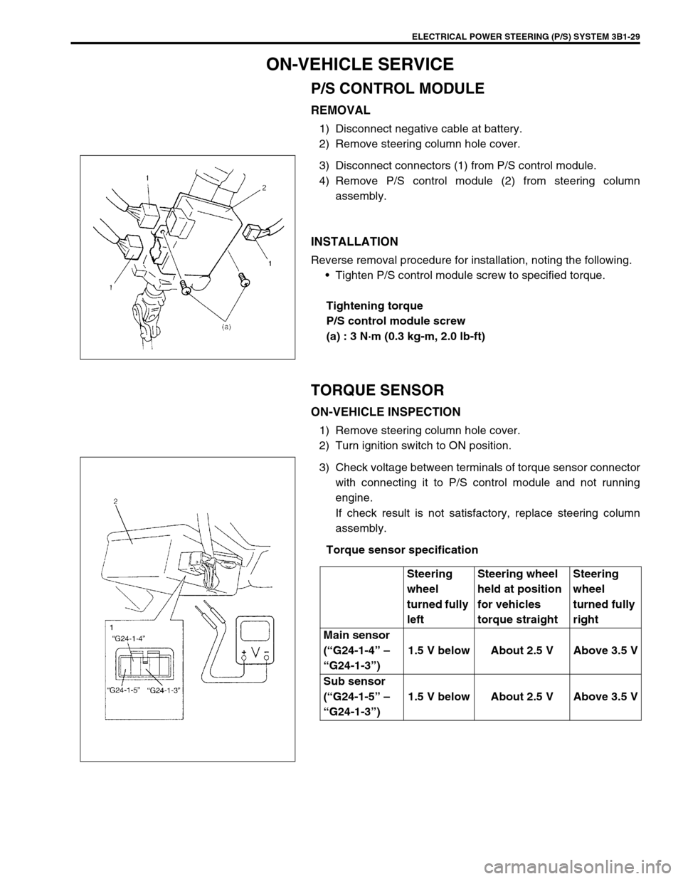
1) Disconnect negative cable at battery.
2) Remove steering column hole cover.
3) Disconnect connectors (1) from P/S control module.
4) Remove P/S control module (2) from steering column
assembly.
INSTALLATION
Reverse removal procedure for installation, noting the following.
Tighten P/S control module screw to specified torque.
Tightening torque
P/S control module screw
(a) : 3 N·m (0.3 kg-m, 2.0 lb-ft)
TORQUE SENSOR
ON-VEHICLE INSPECTION
1) Remove steering column hole cover.
2) Turn ignition switch to ON position.
3) Check voltage between terminals of torque sensor connector
with connecting it to P/S control module and not running
engine.
If check result is not satisfactory, replace steering column
assembly.
Torque sensor specification
Steering
wheel
turned fully
leftSteering wheel
held at position
for vehicles
torque straightSteering
wheel
turned fully
right
Main sensor
(“G24-1-4” –
“G24-1-3”)1.5 V below About 2.5 V Above 3.5 V
Sub sensor
(“G24-1-5” –
“G24-1-3”)1.5 V below About 2.5 V Above 3.5 V