2000 SUZUKI SWIFT spark plugs replace
[x] Cancel search: spark plugs replacePage 31 of 698

0B-2 MAINTENANCE AND LUBRICATION
MAINTENANCE SCHEDULE
MAINTENANCE SCHEDULE UNDER NORMAL DRIVING CONDITIONS
NOTE:
This interval should be judged by odometer reading or months, whichever comes first.
This table includes service as scheduled up to 90,000 km (54,000 miles) mileage. Beyond 90,000 km
(54,000 miles), carry out the same services at the same intervals respectively.
IntervalKm (x 1,000) 15 30 45 60 75 90
Miles (x 1,000) 9 1827364554
Months 12 24 36 48 60 72
ENGINE
Drive belt––I––R
Valve lash (clearance) –I–I–I
Engine oil and oil filter R R R R R R
Engine coolant––R––R
Exhaust system–I–I–I
IGNITION SYSTEM
✱Spark plugs When
unleaded
fuel is usedVehicle without
HO2SNickel plug–R–R–R
Iridium plug–––R––
Vehicle with
HO2SNickel plug––R––R
Iridium plug Replace every 105,000 km (63,000 miles) or
84 months
When leaded fuel is used, refer to “MAINTENANCE RECOMMENDED UNDER SEVERE
DRIVING CONDTION” in this section.
FUEL SYSTEM
Air cleaner filter Paved-road I I R I I R
Dusty conditions Refer to “MAINTENANCE RECOM-
MENDED UNDER SEVERE DRIVING CON-
DITIONS” in this section.
Fuel lines and connections–I–I–I
Fuel filter Replace every 105,000 km (63,000 miles)
Fuel tank––I––I
EMISSION CONTROL SYSTEM
✱PCV valve Vehicle without HO2S––I––I
Vehicle with HO2S–––––I
✱Fuel evaporative emission control system–––––I
NOTE:
“R” : Replace or change
“I” : Inspect and correct, replace or lubricate if necessary
For Sweden, items with
✱
✱✱ ✱ (asterisk) should be performed by odometer reading only.
For spark plugs, replace every 50,000 km if the local law requires.
Nickel spark plug : BKR6E-11 (NGK) or K20PR-U11 (DENSO)
Iridium spark plug : IFR5E11 (NGK)
Page 33 of 698

0B-4 MAINTENANCE AND LUBRICATION
MAINTENANCE RECOMMENDED UNDER SEVERE DRIVING CONDITIONS
If the vehicle is usually used under the conditions corresponding to any severe condition code given below, IT IS
RECOMMENDED that applicable maintenance operation be performed at the particular interval as shown in the
following table.
Severe condition code :
A : Repeated short trips
B : Driving on rough and/or muddy roads
C : Driving on dusty roads
D : Driving in extremely cold weather and/or salted roads
E : Repeated short trips in extremely cold weather
F : Leaded fuel use
G : – – – – –
H : Towing a trailer (if admitted)
Severe
Condition CodeMaintenanceMaintenance
OperationMaintenance Interval
– B C D – – – –Drive beltIEvery 15,000 km
(9,000 miles) or 12 months
REvery 45,000 km
(27,000 miles) or 36 months
A – C D E F – H Engine oil and oil filter REvery 5,000 km
(3,000 miles) or 4 months
– – C – – – – –Air cleaner filter ✱1IEvery 2,500 km
(1,500 miles)
REvery 30,000 km
(18,000 miles) or 24 months
A B C – E F – H Spark plugsNickel spark plug
REvery 10,000 km
(6,000 miles) or 8 months
Iridium spark plug
REvery 30,000 km
(18,000 miles) or 24 months
– B C D – – – H Wheel bearings IEvery 15,000 km
(9,000 miles) or 12 months
– B – D E – – H Drive shafts and propeller shafts (4WD) IEvery 15,000 km
(9,000 miles) or 12 months
– B – – E – – HManual transmission, transfer (4WD) and
differential oil (4WD)REvery 30,000 km
(18,000 miles) or 24 months
– B – – E – – H Automatic transmission fluid REvery 30,000 km
(18,000 miles) or 24 months
NOTE:
“I” : Inspect and correct or replace if necessary
“R” : Replace or change
✱
✱✱ ✱1 : Inspect more frequently if the vehicle is used under dusty conditions.
Page 39 of 698
0B-10 MAINTENANCE AND LUBRICATION
EXHAUST SYSTEM
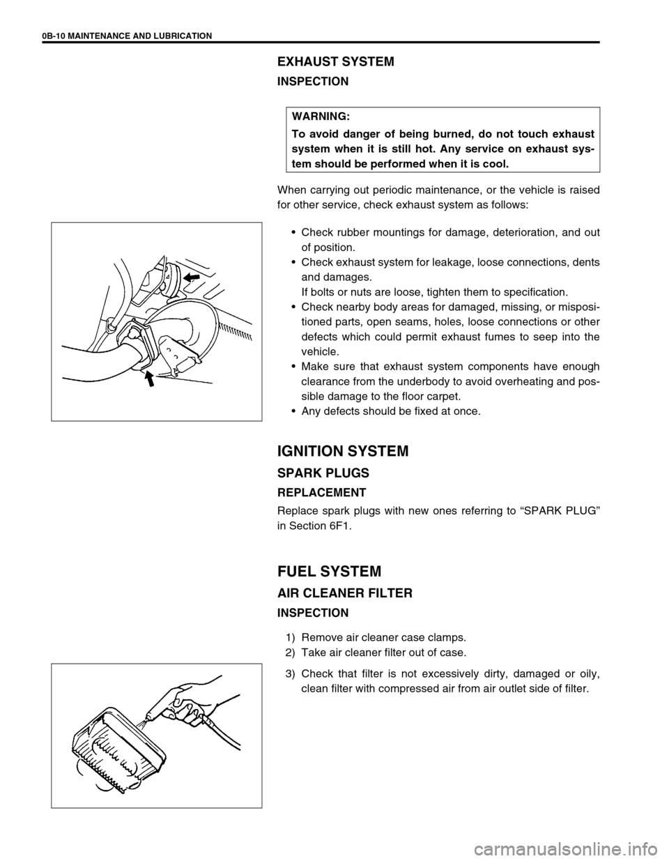
INSPECTION
When carrying out periodic maintenance, or the vehicle is raised
for other service, check exhaust system as follows:
Check rubber mountings for damage, deterioration, and out
of position.
Check exhaust system for leakage, loose connections, dents
and damages.
If bolts or nuts are loose, tighten them to specification.
Check nearby body areas for damaged, missing, or misposi-
tioned parts, open seams, holes, loose connections or other
defects which could permit exhaust fumes to seep into the
vehicle.
Make sure that exhaust system components have enough
clearance from the underbody to avoid overheating and pos-
sible damage to the floor carpet.
Any defects should be fixed at once.
IGNITION SYSTEM
SPARK PLUGS
REPLACEMENT
Replace spark plugs with new ones referring to “SPARK PLUG”
in Section 6F1.
FUEL SYSTEM
AIR CLEANER FILTER
INSPECTION
1) Remove air cleaner case clamps.
2) Take air cleaner filter out of case.
3) Check that filter is not excessively dirty, damaged or oily,
clean filter with compressed air from air outlet side of filter. WARNING:
To avoid danger of being burned, do not touch exhaust
system when it is still hot. Any service on exhaust sys-
tem should be performed when it is cool.
Page 452 of 698

ENGINE GENERAL INFORMATION AND DIAGNOSIS 6-83
2 Is there DTC other than Fuel system (DTC P0171/
P0172) and misfire (DTC P0300-P0304)?Go to applicable DTC
Diag. Flow Table.Go to Step 3.
3 Check Ignition System.
1) Remove spark plugs and check them for;
Air gap : 1.0 – 1.1 mm (0.040 – 0.043 in.) See Fig. 1.
Carbon deposits/Insulator damage/Plug type
If abnormality is found, adjust, clean or replace.
2) Disconnect all injector connectors.
3) Connect spark plugs to high tension cords and then
ground spark plugs.
4) Crank engine and check that each spark plug sparks.
Are above check results satisfactory?Go to Step 4. Check ignition sys-
tem parts (Refer to
Section 6F1)
4 Check Fuel Pressure (Refer to Section 6E1 for details).
1) Release fuel pressure from fuel feed line.
2) Install fuel pressure gauge. See Fig. 2.
3) Check fuel pressure.
With fuel pump operating and engine at stop : 270 –
310 kPa, 2.7 – 3.1 kg/cm
2, 38.4 – 44.0 psi.
At specified idle speed : 270 – 310 kPa, 2.7 – 3.1 kg/
cm
2, 38.4 – 44.0 psi.
Is measured value as specified?Go to Step 5. Go to Diag. Flow
Table B-3 fuel
pressure check.
5 Check Fuel Injectors and Circuit.
1) Using sound scope (1) or such, check operating
sound of each injector (2) when engine is running.
Cycle of operating sound should very according to
engine speed. See Fig 3.
If no sound or an unusual sound is heard, check
injector circuit (wire or connector) or injector.
2) Turn ignition switch OFF and disconnect a fuel injec-
tor connector.
3) Check for proper connection to fuel injector at each
terminal. See Fig. 4.
4) If OK, then check injector resistance.
Injector Resistance : 11.3 – 13.8 ohm at 20°C (68°F)
5) Carry out steps 1) and 3) on each injector.
6) Check each injector for injected fuel volume referring
to Section 6E1. See Fig. 5.
Injected Fuel Volume : 43 – 47 cc/15 sec (1.45/1.51 –
1.58/1.65 US/Imp. oz/15 sec)
7) Check each injector for fuel leakage after injector
closed.
Fuel Leakage : Less than 1 drop/min.
Is check result in step 1) and 3) to 7) satisfactory?Go to Step 6. Check injector cir-
cuit or replace fuel
injector(s).
6 Check PCV Valve for clogging (See Section 6E1).
Is it in good condition?Go to Step 7. Replace PCV
valve. Step Action Yes No
Page 665 of 698
IGNITION SYSTEM (ELECTRONIC IGNITION SYSTEM 6F1-3
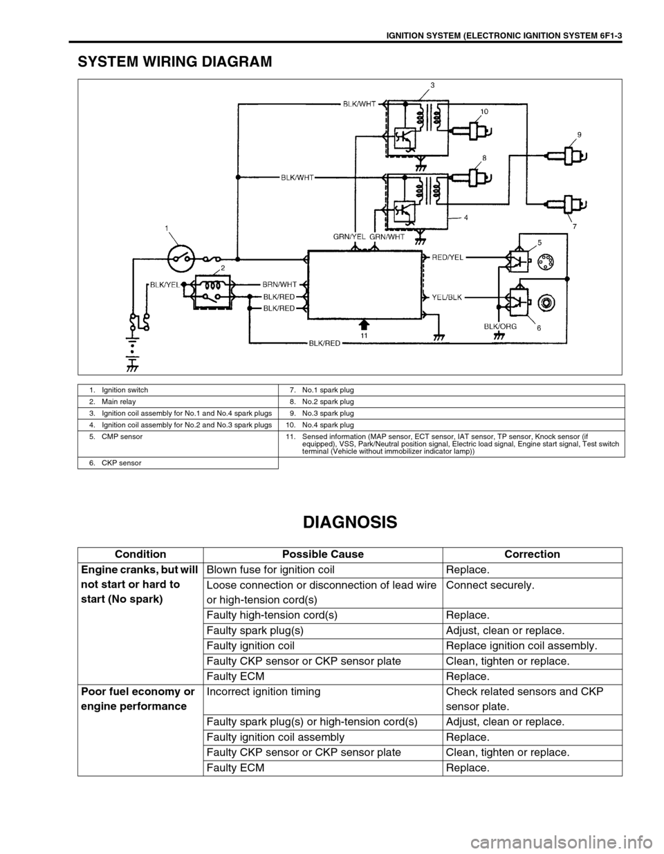
SYSTEM WIRING DIAGRAM
DIAGNOSIS
1. Ignition switch 7. No.1 spark plug
2. Main relay 8. No.2 spark plug
3. Ignition coil assembly for No.1 and No.4 spark plugs 9. No.3 spark plug
4. Ignition coil assembly for No.2 and No.3 spark plugs 10. No.4 spark plug
5. CMP sensor 11. Sensed information (MAP sensor, ECT sensor, IAT sensor, TP sensor, Knock sensor (if
equipped), VSS, Park/Neutral position signal, Electric load signal, Engine start signal, Test switch
terminal (Vehicle without immobilizer indicator lamp))
6. CKP sensor
Condition Possible Cause Correction
Engine cranks, but will
not start or hard to
start (No spark)Blown fuse for ignition coil Replace.
Loose connection or disconnection of lead wire
or high-tension cord(s)Connect securely.
Faulty high-tension cord(s) Replace.
Faulty spark plug(s) Adjust, clean or replace.
Faulty ignition coil Replace ignition coil assembly.
Faulty CKP sensor or CKP sensor plate Clean, tighten or replace.
Faulty ECM Replace.
Poor fuel economy or
engine performanceIncorrect ignition timing Check related sensors and CKP
sensor plate.
Faulty spark plug(s) or high-tension cord(s) Adjust, clean or replace.
Faulty ignition coil assembly Replace.
Faulty CKP sensor or CKP sensor plate Clean, tighten or replace.
Faulty ECM Replace.
Page 666 of 698
6F1-4 IGNITION SYSTEM (ELECTRONIC IGNITION SYSTEM)
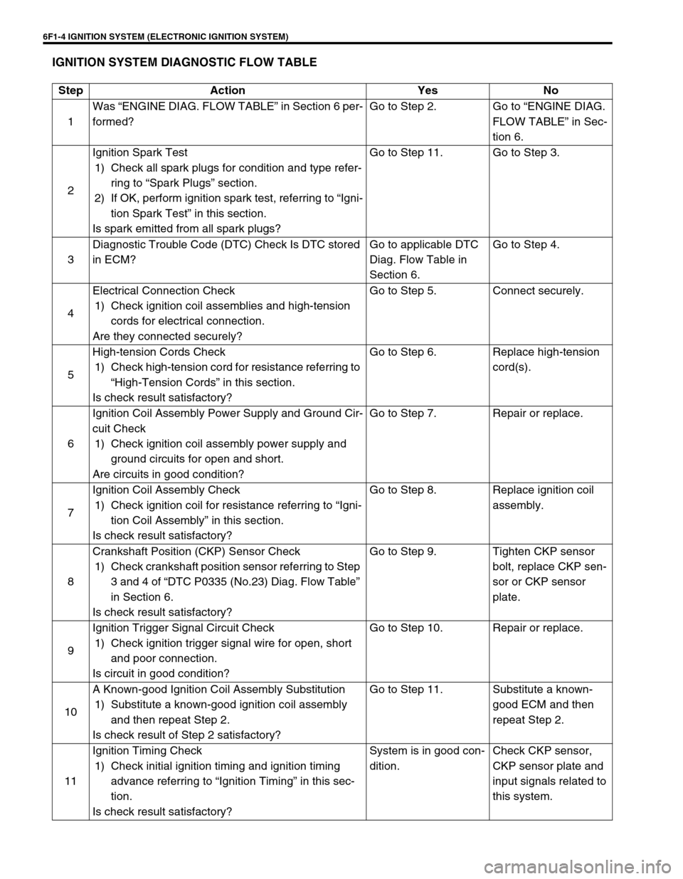
IGNITION SYSTEM DIAGNOSTIC FLOW TABLE
Step Action Yes No
1Was “ENGINE DIAG. FLOW TABLE” in Section 6 per-
formed?Go to Step 2. Go to “ENGINE DIAG.
FLOW TABLE” in Sec-
tion 6.
2Ignition Spark Test
1) Check all spark plugs for condition and type refer-
ring to “Spark Plugs” section.
2) If OK, perform ignition spark test, referring to “Igni-
tion Spark Test” in this section.
Is spark emitted from all spark plugs?Go to Step 11. Go to Step 3.
3Diagnostic Trouble Code (DTC) Check Is DTC stored
in ECM?Go to applicable DTC
Diag. Flow Table in
Section 6.Go to Step 4.
4Electrical Connection Check
1) Check ignition coil assemblies and high-tension
cords for electrical connection.
Are they connected securely?Go to Step 5. Connect securely.
5High-tension Cords Check
1) Check high-tension cord for resistance referring to
“High-Tension Cords” in this section.
Is check result satisfactory?Go to Step 6. Replace high-tension
cord(s).
6Ignition Coil Assembly Power Supply and Ground Cir-
cuit Check
1) Check ignition coil assembly power supply and
ground circuits for open and short.
Are circuits in good condition?Go to Step 7. Repair or replace.
7Ignition Coil Assembly Check
1) Check ignition coil for resistance referring to “Igni-
tion Coil Assembly” in this section.
Is check result satisfactory?Go to Step 8. Replace ignition coil
assembly.
8Crankshaft Position (CKP) Sensor Check
1) Check crankshaft position sensor referring to Step
3 and 4 of “DTC P0335 (No.23) Diag. Flow Table”
in Section 6.
Is check result satisfactory?Go to Step 9. Tighten CKP sensor
bolt, replace CKP sen-
sor or CKP sensor
plate.
9Ignition Trigger Signal Circuit Check
1) Check ignition trigger signal wire for open, short
and poor connection.
Is circuit in good condition?Go to Step 10. Repair or replace.
10A Known-good Ignition Coil Assembly Substitution
1) Substitute a known-good ignition coil assembly
and then repeat Step 2.
Is check result of Step 2 satisfactory?Go to Step 11. Substitute a known-
good ECM and then
repeat Step 2.
11Ignition Timing Check
1) Check initial ignition timing and ignition timing
advance referring to “Ignition Timing” in this sec-
tion.
Is check result satisfactory?System is in good con-
dition.Check CKP sensor,
CKP sensor plate and
input signals related to
this system.
Page 667 of 698
IGNITION SYSTEM (ELECTRONIC IGNITION SYSTEM 6F1-5
ON-VEHICLE SERVICE
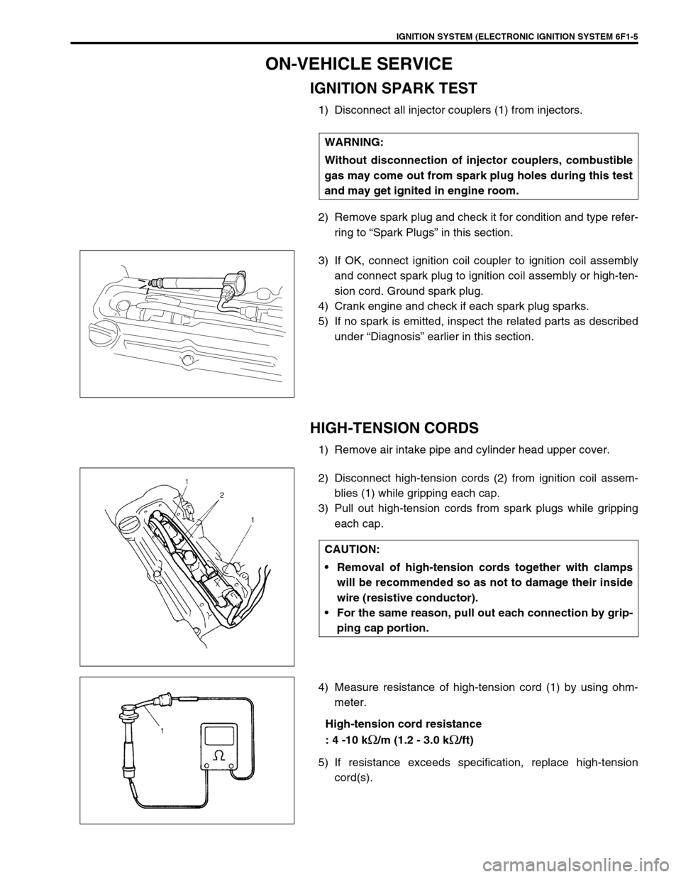
IGNITION SPARK TEST
1) Disconnect all injector couplers (1) from injectors.
2) Remove spark plug and check it for condition and type refer-
ring to “Spark Plugs” in this section.
3) If OK, connect ignition coil coupler to ignition coil assembly
and connect spark plug to ignition coil assembly or high-ten-
sion cord. Ground spark plug.
4) Crank engine and check if each spark plug sparks.
5) If no spark is emitted, inspect the related parts as described
under “Diagnosis” earlier in this section.
HIGH-TENSION CORDS
1) Remove air intake pipe and cylinder head upper cover.
2) Disconnect high-tension cords (2) from ignition coil assem-
blies (1) while gripping each cap.
3) Pull out high-tension cords from spark plugs while gripping
each cap.
4) Measure resistance of high-tension cord (1) by using ohm-
meter.
High-tension cord resistance
: 4 -10 k
Ω/m (1.2 - 3.0 kΩ/ft)
5) If resistance exceeds specification, replace high-tension
cord(s). WARNING:
Without disconnection of injector couplers, combustible
gas may come out from spark plug holes during this test
and may get ignited in engine room.
CAUTION:
Removal of high-tension cords together with clamps
will be recommended so as not to damage their inside
wire (resistive conductor).
For the same reason, pull out each connection by grip-
ping cap portion.
Page 668 of 698
6F1-6 IGNITION SYSTEM (ELECTRONIC IGNITION SYSTEM)
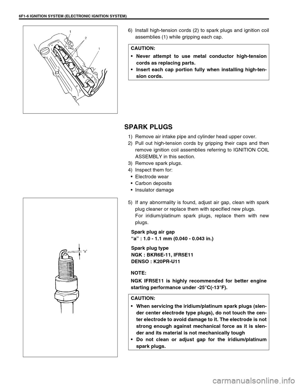
6) Install high-tension cords (2) to spark plugs and ignition coil
assemblies (1) while gripping each cap.
SPARK PLUGS
1) Remove air intake pipe and cylinder head upper cover.
2) Pull out high-tension cords by gripping their caps and then
remove ignition coil assemblies referring to IGNITION COIL
ASSEMBLY in this section.
3) Remove spark plugs.
4) Inspect them for:
Electrode wear
Carbon deposits
Insulator damage
5) If any abnormality is found, adjust air gap, clean with spark
plug cleaner or replace them with specified new plugs.
For iridium/platinum spark plugs, replace them with new
plugs.
Spark plug air gap
“a” : 1.0 - 1.1 mm (0.040 - 0.043 in.)
Spark plug type
NGK : BKR6E-11, IFR5E11
DENSO : K20PR-U11 CAUTION:
Never attempt to use metal conductor high-tension
cords as replacing parts.
Insert each cap portion fully when installing high-ten-
sion cords.
NOTE:
NGK IFR5E11 is highly recommended for better engine
starting performance under -25°C(-13°F).
CAUTION:
When servicing the iridium/platinum spark plugs (slen-
der center electrode type plugs), do not touch the cen-
ter electrode to avoid damage to it. The electrode is not
strong enough against mechanical force as it is slen-
der and its material is not mechanically tough
Do not clean or adjust gap for the iridium/platinum
spark plugs.