Page 68 of 698
AIR CONDITIONING (OPTIONAL) 1B-3
GENERAL DESCRIPTION
REFRIGERANT CIRCULATION
REFRIGERANT TYPE
Whether the A/C in the vehicle being serviced uses HFC-134a
(R-134a) or CFC-12 (R-12) is indicated on compressor label (1).
Also, it can be checked by the shape of the service (charge) valve
(2).
1. Compressor 4. Receiver/dryer 7. Evaporator
2. Magnet clutch 5. A/C refrigerant pressure switch
3. Condenser assembly 6. Expansion valve
Page 75 of 698
1B-10 AIR CONDITIONING (OPTIONAL)
PERFORMANCE DIAGNOSIS
1) Confirm that vehicle and environmental conditions are as fol-
lows.
Vehicle is not exposed to direct sun.
Ambient temperature is within 15 – 35°C (59 – 95°F).
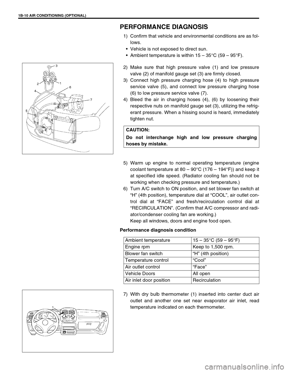
2) Make sure that high pressure valve (1) and low pressure
valve (2) of manifold gauge set (3) are firmly closed.
3) Connect high pressure charging hose (4) to high pressure
service valve (5), and connect low pressure charging hose
(6) to low pressure service valve (7).
4) Bleed the air in charging hoses (4), (6) by loosening their
respective nuts on manifold gauge set (3), utilizing the refrig-
erant pressure. When a hissing sound is heard, immediately
tighten nut.
5) Warm up engine to normal operating temperature (engine
coolant temperature at 80 – 90°C (176 – 194°F)) and keep it
at specified idle speed. (Radiator cooling fan should not be
working when checking pressure and temperature.)
6) Turn A/C switch to ON position, and set blower fan switch at
“H” (4th position), temperature dial at “COOL”, air outlet con-
trol dial at “FACE” and fresh/recirculation control dial at
“RECIRCULATION”. (Confirm that A/C compressor and radi-
ator/condenser cooling fan are working.)
Keep all windows, doors and engine food open.
Performance diagnosis condition
7) With dry bulb thermometer (1) inserted into center duct air
outlet and another one set near evaporator air inlet, read
temperature indicated on each thermometer. CAUTION:
Do not interchange high and low pressure charging
hoses by mistake.
Ambient temperature 15 – 35°C (59 – 95°F)
Engine rpm Keep to 1,500 rpm.
Blower fan switch“H” (4th position)
Temperature control“Cool”
Air outlet control“Face”
Vehicle Doors All open
Air inlet door position Recirculation
Page 89 of 698
1B-24 AIR CONDITIONING (OPTIONAL)
CHARGING
CHARGING PROCEDURE
The initial charging of the A/C system is performed from the high
pressure side with the engine stopped.
And next, this method must be followed by charging from the low
pressure side with the engine running.
1) Check to make sure that hoses are routed properly after
evacuating the system.
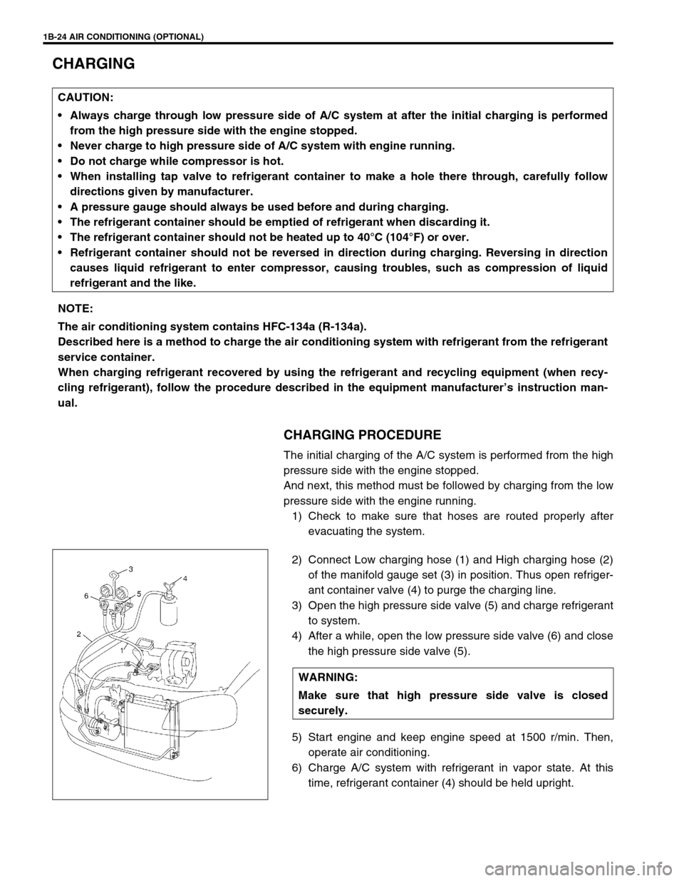
2) Connect Low charging hose (1) and High charging hose (2)
of the manifold gauge set (3) in position. Thus open refriger-
ant container valve (4) to purge the charging line.
3) Open the high pressure side valve (5) and charge refrigerant
to system.
4) After a while, open the low pressure side valve (6) and close
the high pressure side valve (5).
5) Start engine and keep engine speed at 1500 r/min. Then,
operate air conditioning.
6) Charge A/C system with refrigerant in vapor state. At this
time, refrigerant container (4) should be held upright. CAUTION:
Always charge through low pressure side of A/C system at after the initial charging is performed
from the high pressure side with the engine stopped.
Never charge to high pressure side of A/C system with engine running.
Do not charge while compressor is hot.
When installing tap valve to refrigerant container to make a hole there through, carefully follow
directions given by manufacturer.
A pressure gauge should always be used before and during charging.
The refrigerant container should be emptied of refrigerant when discarding it.
The refrigerant container should not be heated up to 40°C (104°F) or over.
Refrigerant container should not be reversed in direction during charging. Reversing in direction
causes liquid refrigerant to enter compressor, causing troubles, such as compression of liquid
refrigerant and the like.
NOTE:
The air conditioning system contains HFC-134a (R-134a).
Described here is a method to charge the air conditioning system with refrigerant from the refrigerant
service container.
When charging refrigerant recovered by using the refrigerant and recycling equipment (when recy-
cling refrigerant), follow the procedure described in the equipment manufacturer’s instruction man-
ual.
WARNING:
Make sure that high pressure side valve is closed
securely.
Page 91 of 698
1B-26 AIR CONDITIONING (OPTIONAL)
REMOVING MANIFOLD GAUGE SET
When A/C system has been charged with a specified amount of refrigerant, remove manifold gauge set as fol-
lows :
1) Close low pressure side valve of manifold gauge set. (The high pressure side valve is closed continuously
during the process of charging.)
2) Close refrigerant container valve.
3) Stop engine.
4) Using shop rag, remove charging hoses from service valves. This operation must be performed rapidly.
5) Put caps on service valves.
LEAK TEST
Whenever a refrigerant leak is suspected in the system or any
service operation has been performed which may result in dis-
turbing lines or connections, it is advisable to test for leaks.
Common sense should be used in performing any refrigerant leak
test, since the need and extent of any such test will, in general,
depend upon the nature of a complaint and the type of a service
performed on the system.
LIQUID LEAK DETECTORS
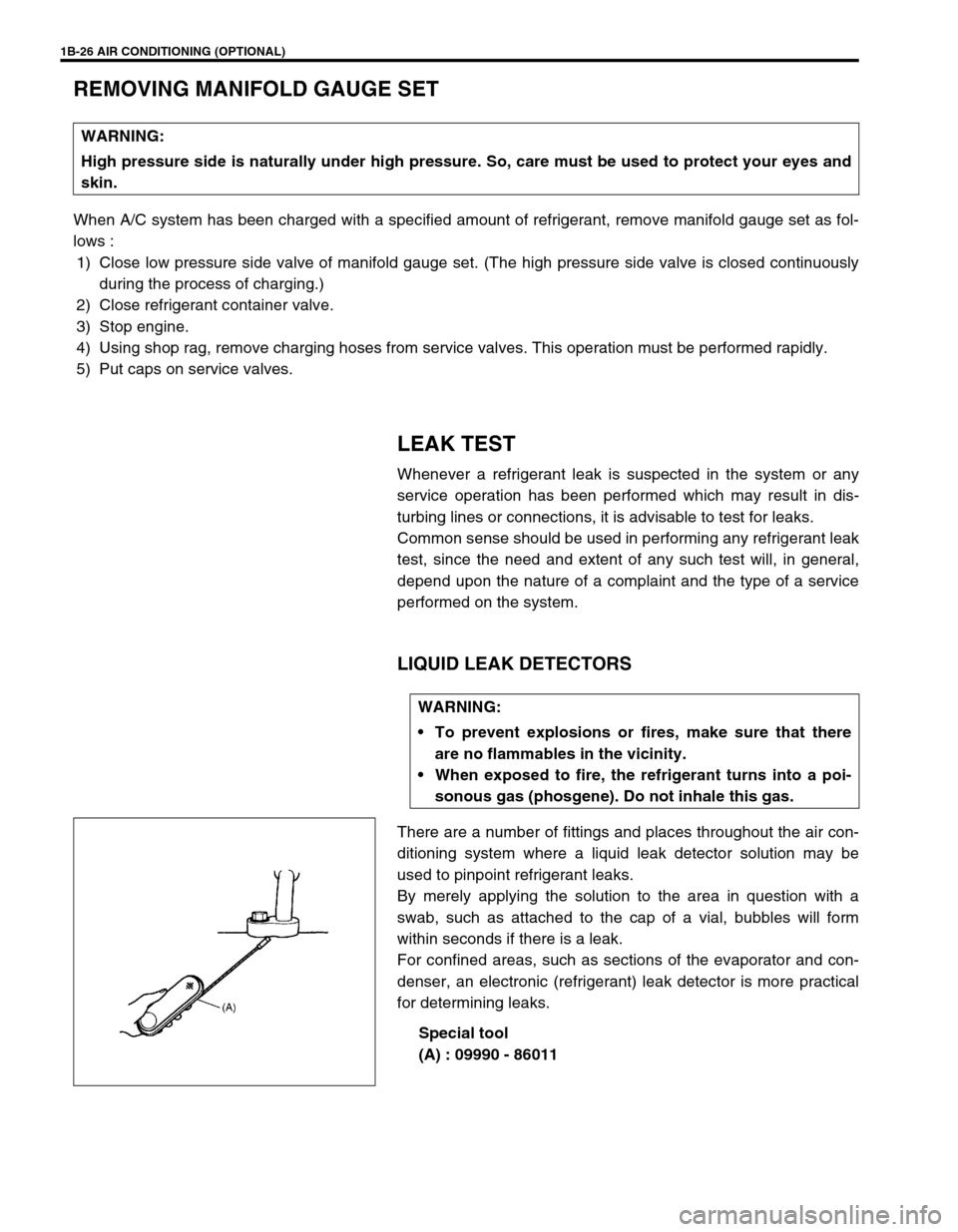
There are a number of fittings and places throughout the air con-
ditioning system where a liquid leak detector solution may be
used to pinpoint refrigerant leaks.
By merely applying the solution to the area in question with a
swab, such as attached to the cap of a vial, bubbles will form
within seconds if there is a leak.
For confined areas, such as sections of the evaporator and con-
denser, an electronic (refrigerant) leak detector is more practical
for determining leaks.
Special tool
(A) : 09990 - 86011 WARNING:
High pressure side is naturally under high pressure. So, care must be used to protect your eyes and
skin.
WARNING:
To prevent explosions or fires, make sure that there
are no flammables in the vicinity.
When exposed to fire, the refrigerant turns into a poi-
sonous gas (phosgene). Do not inhale this gas.
Page 92 of 698
AIR CONDITIONING (OPTIONAL) 1B-27
ON-VEHICLE SERVICE
SERVICE PRECAUTION
When servicing air conditioning system, note the following instructions.
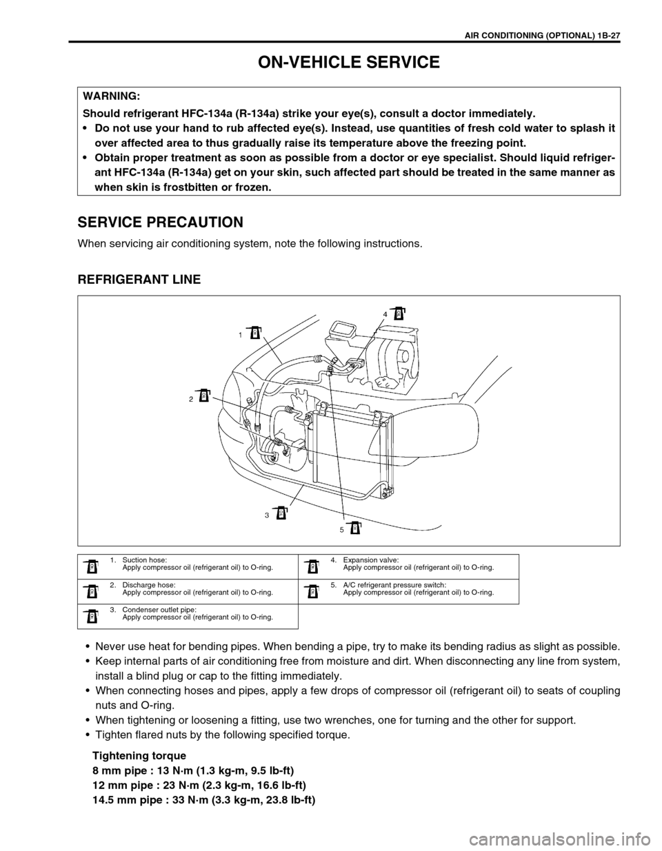
REFRIGERANT LINE
Never use heat for bending pipes. When bending a pipe, try to make its bending radius as slight as possible.
Keep internal parts of air conditioning free from moisture and dirt. When disconnecting any line from system,
install a blind plug or cap to the fitting immediately.
When connecting hoses and pipes, apply a few drops of compressor oil (refrigerant oil) to seats of coupling
nuts and O-ring.
When tightening or loosening a fitting, use two wrenches, one for turning and the other for support.
Tighten flared nuts by the following specified torque.
Tightening torque
8 mm pipe : 13 N·m (1.3 kg-m, 9.5 lb-ft)
12 mm pipe : 23 N·m (2.3 kg-m, 16.6 lb-ft)
14.5 mm pipe : 33 N·m (3.3 kg-m, 23.8 lb-ft) WARNING:
Should refrigerant HFC-134a (R-134a) strike your eye(s), consult a doctor immediately.
Do not use your hand to rub affected eye(s). Instead, use quantities of fresh cold water to splash it
over affected area to thus gradually raise its temperature above the freezing point.
Obtain proper treatment as soon as possible from a doctor or eye specialist. Should liquid refriger-
ant HFC-134a (R-134a) get on your skin, such affected part should be treated in the same manner as
when skin is frostbitten or frozen.
1. Suction hose:
Apply compressor oil (refrigerant oil) to O-ring.4. Expansion valve:
Apply compressor oil (refrigerant oil) to O-ring.
2. Discharge hose:
Apply compressor oil (refrigerant oil) to O-ring.5. A/C refrigerant pressure switch:
Apply compressor oil (refrigerant oil) to O-ring.
3. Condenser outlet pipe:
Apply compressor oil (refrigerant oil) to O-ring.
Page 108 of 698
AIR CONDITIONING (OPTIONAL) 1B-43
6) Tighten new front head mounting bolts (a), (b).
Tightening torque
Front head bolt (a) : 9 N·m (0.9 kg-m, 6.5 lb-ft)
Front head bolt (b) : 22 N·m (2.2 kg-m, 16.0 lb-ft)
REQUIRED SERVICE MATERIAL
NOTE:
Be sure to use new front head mounting bolts.
Tighten bolt (a) first, and next (b).
MaterialRecommended SUZUKI product
(Part Number)Use
Compressor oil
(Refrigerant oil)COMPRESSOR OIL RS20 (150 cc)
99000-99088O-ring
Each component
Refrigerant REFRIGERANT DRUM (200 g)
95794-50G00Refrigerant charge
Sealant SUZUKI BOND No.1216B
99000-31160Cooling unit
Page 116 of 698
STEERING, SUSPENSION, WHEELS AND TIRES 3-7
RADIAL TIRE LEAD
“Lead” is the deviation of the vehicle from a straight path on a level rod even with no pressure on the steering
wheel.
Lead is usually caused by:
Incorrect alignment.
Uneven brake adjustment.
Tire construction.
The way in which a tire is built can produce lead in a vehicle. An example of this is placement of the belt. Off
center belts on radial tires can cause the tire to develop a side force while rolling straight down the road. If one
side of the tire has a little larger diameter than the other, the tire will tend to roll to one side. This will develop a
side force which can produce vehicle lead.
The procedure in above figure (Lead Diagnosis) should be used to make sure that front alignment is not mis-
taken for tire lead.
Part of the lead diagnosis procedure is different from the proper tire rotation pattern currently in the owner
and service manuals. If a medium to high mileage tire is moved to the other side of the vehicle, be sure to
check that ride roughness has not developed
Rear tires will not cause lead.
VIBRATION DIAGNOSIS
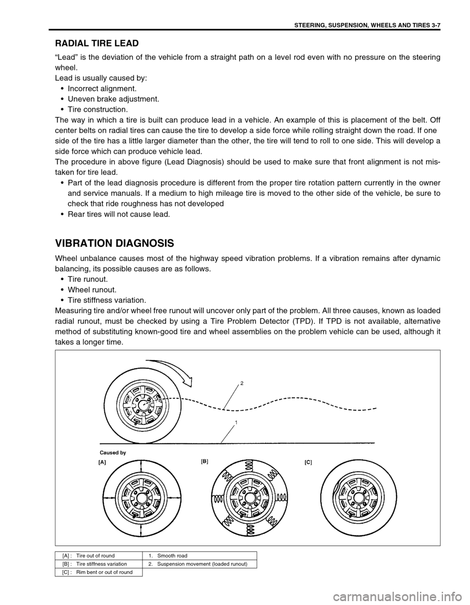
Wheel unbalance causes most of the highway speed vibration problems. If a vibration remains after dynamic
balancing, its possible causes are as follows.
Tire runout.
Wheel runout.
Tire stiffness variation.
Measuring tire and/or wheel free runout will uncover only part of the problem. All three causes, known as loaded
radial runout, must be checked by using a Tire Problem Detector (TPD). If TPD is not available, alternative
method of substituting known-good tire and wheel assemblies on the problem vehicle can be used, although it
takes a longer time.
[A] : Tire out of round 1. Smooth road
[B] : Tire stiffness variation 2. Suspension movement (loaded runout)
[C] : Rim bent or out of round
Page 118 of 698
FRONT END ALIGNMENT 3A-1
6F1
6F2
6G
6H
6K
7A
3A
7B1
7C1
7D
7E
7F
8A
8B
8C
8D
8E
9
10
10A
10B
SECTION 3A
FRONT END ALIGNMENT
CONTENTS
GENERAL DESCRIPTION ...............................3A-2
TOE SETTING .............................................. 3A-2
CAMBER ....................................................... 3A-2
ALIGNMENT SERVICE DATA
(REFERENCE) .............................................. 3A-2
DIAGNOSIS ......................................................3A-3
DIAGNOSIS TABLE ...................................... 3A-3
PRELIMINARY CHECKS PRIOR TO
ADJUSTING FRONT ALIGNMENT............... 3A-3TOE ADJUSTMENT ..................................... 3A-3
CAMBER AND CASTER CHECK AND
ADJUSTMENT .............................................. 3A-4
STEERING ANGLE CHECK AND
ADJUSTMENT .............................................. 3A-4
SIDE SLIP (REFERENCE) ........................... 3A-4