2000 SUZUKI SWIFT load capacity
[x] Cancel search: load capacityPage 247 of 698

3F-2 WHEELS AND TIRES
GENERAL DESCRIPTION
TIRES
This vehicle is equipped with the following tire.
Tire size
: 165/70R14
The tire is of tubeless type. The tire is designed to operate satisfactorily with loads up to the full rated load
capacity when inflated to the recommended inflation pressures.
Correct tire pressures and driving habits have an important influence on tire life. Heavy cornering, excessively
rapid acceleration, and unnecessary sharp braking increase tire wear.
WHEELS
Standard equipment wheels are the following steel wheel.
Wheel size
: 14 x 4 1/2 J
REPLACEMENT TIRES
When replacement is necessary, the original equipment type tire should be used. Refer to the “Tire Placard”.
Replacement tires should be of the same size, load range and construction as those originally on the vehicle.
Use of any other size or type tire may affect ride, handling, speedometer/odometer calibration, vehicle ground
clearance and tire or snow chain clearance to the body and chassis.
It is recommended that new tires be installed in pairs on the same axle. If necessary to replace only one tire, it
should be paired with the tire having the most tread, to equalize braking traction.
The metric term for tire inflation pressure is the kilo pascal (kPa).
Tire pressures is usually printed in both kPa and psi on the “Tire
Placard”.
Metric tire gauges are available from tool suppliers.
The chart, shown the table, converts commonly used inflation
pressures from kPa to psi.
REPLACEMENT WHEELS
Wheels must be replaced if they are bent, dented, have excessive lateral or radial runout, air leak through
welds, have elongated bolt holes, if lug nuts won’t stay tight, or if they are heavily rusted. Wheels with greater
runout than shown in figure below may cause objectional vibrations.
Replacement wheels must be equivalent to the original equipment wheels in load capacity, diameter, rim with
offset and mounting configuration. A wheel of improper size or type may affect wheel and bearing life, brake
cooling, speedometer/odometer calibration, vehicle ground clearance and tire clearance to body and chassis.WARNING:
Do not mix different types of tires on the same vehicle such as radial, bias and bias-belted tires except
in emergencies, because handling may be seriously affected and may result in loss of control.
kPa kgf/cm²pis
160 1.6 23
180 1.8 26
200 2.0 29
220 2.2 32
240 2.4 35
260 2.6 38
280 2.8 41
300 3.0 44
Page 328 of 698

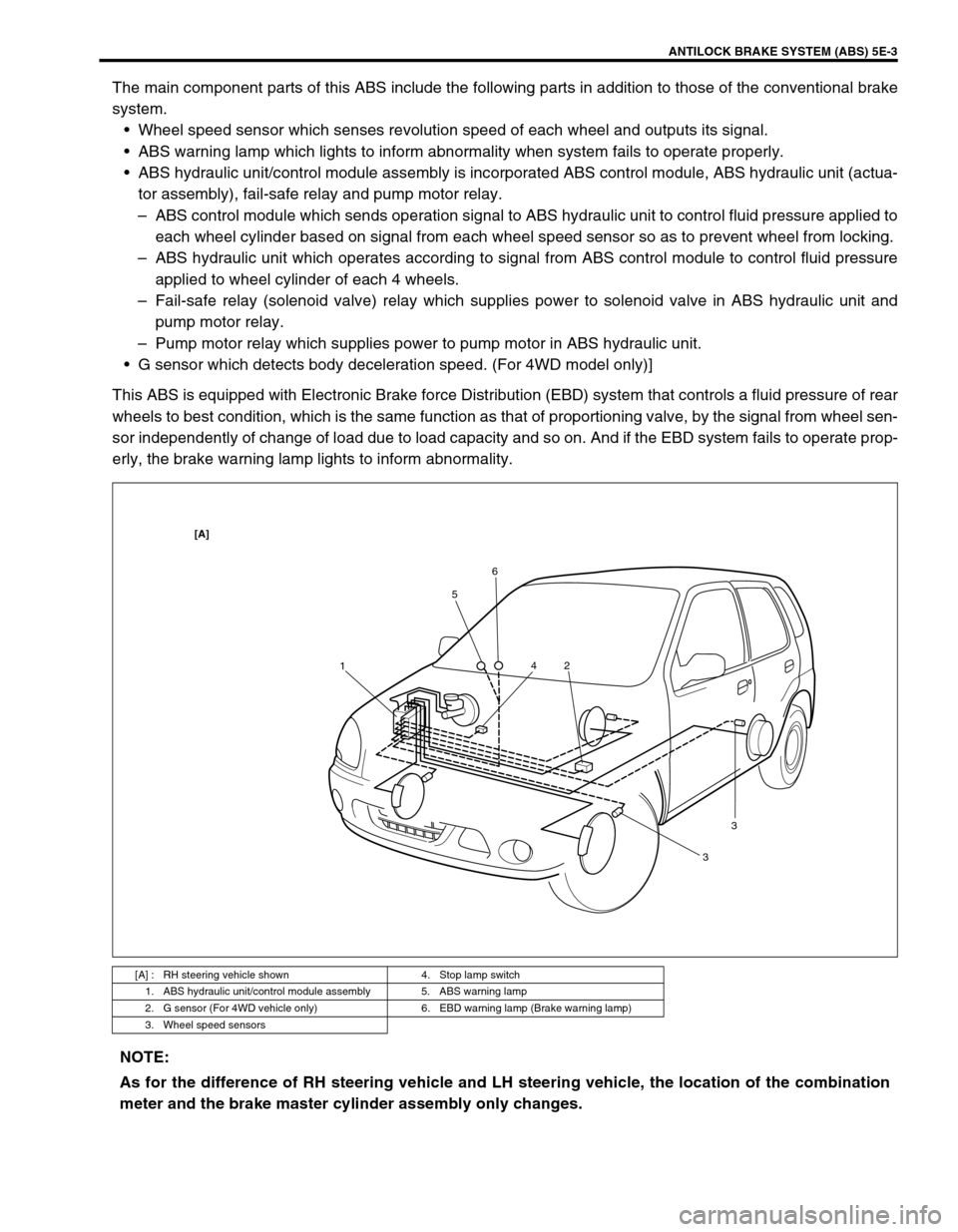
ANTILOCK BRAKE SYSTEM (ABS) 5E-3
The main component parts of this ABS include the following parts in addition to those of the conventional brake
system.
Wheel speed sensor which senses revolution speed of each wheel and outputs its signal.
ABS warning lamp which lights to inform abnormality when system fails to operate properly.
ABS hydraulic unit/control module assembly is incorporated ABS control module, ABS hydraulic unit (actua-
tor assembly), fail-safe relay and pump motor relay.
–ABS control module which sends operation signal to ABS hydraulic unit to control fluid pressure applied to
each wheel cylinder based on signal from each wheel speed sensor so as to prevent wheel from locking.
–ABS hydraulic unit which operates according to signal from ABS control module to control fluid pressure
applied to wheel cylinder of each 4 wheels.
–Fail-safe relay (solenoid valve) relay which supplies power to solenoid valve in ABS hydraulic unit and
pump motor relay.
–Pump motor relay which supplies power to pump motor in ABS hydraulic unit.
G sensor which detects body deceleration speed. (For 4WD model only)]
This ABS is equipped with Electronic Brake force Distribution (EBD) system that controls a fluid pressure of rear
wheels to best condition, which is the same function as that of proportioning valve, by the signal from wheel sen-
sor independently of change of load due to load capacity and so on. And if the EBD system fails to operate prop-
erly, the brake warning lamp lights to inform abnormality.
[A] : RH steering vehicle shown 4. Stop lamp switch
1. ABS hydraulic unit/control module assembly 5. ABS warning lamp
2. G sensor (For 4WD vehicle only) 6. EBD warning lamp (Brake warning lamp)
3. Wheel speed sensors
156
2 4
33
[A]
NOTE:
As for the difference of RH steering vehicle and LH steering vehicle, the location of the combination
meter and the brake master cylinder assembly only changes.
Page 404 of 698

ENGINE GENERAL INFORMATION AND DIAGNOSIS 6-35
RADIATOR FAN (RADIATOR FAN CONTROL RELAY, ON/OFF)
ON : Command for radiator fan control relay operation being output.
OFF : Command for relay operation not being output.
ELECTRIC LOAD (ON/OFF)
ON : Headlight, small light or rear window defogger ON signal inputted.
OFF : Above electric loads all turned OFF.
A/C SWITCH (ON/OFF)
ON : Command for A/C operation being output from ECM to A/C compressor magnet clutch.
OFF : Command for A/C operation not being output.
FUEL TANK LEVEL (%)
This parameter indicates approximate fuel level in the fuel tank. As the detectable range of the fuel level sensor
is set as 0 to 100%, however, with some models whose fuel tank capacity is smaller, the indicated fuel level may
be only 70% even when the fuel tank is full.
PNP SIGNAL (PARK/NEUTRAL POSITION SIGNAL, P/N RANGE or D RANGE)
It is detected by signal from TCM.
D range : A/T is in “R”, “D”, “2” or “L” range.
P/N range : A/T is in “P” or “N” range or the above signal is not inputted from TCM.
EGR VALVE (%)
This parameter indicates opening rate of EGR valve which controls the amount of EGR flow.
Page 682 of 698

6H-2 CHARGING SYSTEM
GENERAL DESCRIPTION
BATTERY
The battery has three major functions in the electrical system.
It is a source of electrical energy for cranking the engine.
It acts as a voltage stabilizer for the electrical system.
It can, for a limited time, provide energy when the electrical load exceeds the output of the generator.
CARRIER AND HOLD-DOWN
The battery carrier should be in good condition so that it will support the battery securely and keep it level.
Before installing the battery, the battery carrier and hold-down clamp should be clean and free from corrosion
and make certain there are no parts in carrier.
To prevent the battery from shaking in its carrier, the hold-down bolts should be tight enough but not over-tight-
ened.
ELECTROLYTE FREEZING
The freezing point of electrolyte depends on its specific gravity. Since freezing may ruin a battery, it should be
protected against freezing by keeping it in a fully charged condition. If a battery is frozen accidentally, it should
not be charged until it is warmed.
SULFATION
If the battery is allowed to stand for a long period in discharged condition, the lead sulfate becomes converted
into a hard, crystalline substance, which will not easily turn back to the active material again during the subse-
quent recharging. “Sulfation” means the result as well as the process of that reaction. Such a battery can be
revived by very slow charging and may be restored to usable condition but its capacity is lower than before.
BUILT-IN INDICATOR (IF EQUIPPED)
The battery has a built-in temperature compensated indicator in the top of the battery. This indicator is to be
used with the following diagnostic procedure. When checking the indicator, make sure that the battery has a
clean top. A light may be needed in some poorly-lit areas.
Three types of indication available under normal operation are as
follows.
Green Dot
Battery is sufficiently charged for testing.
Dark
Battery must be charged before testing.
If there is a cranking complaint, battery should be tested as
described in Diagnosis section. Charging and electrical sys-
tems should also be checked at this time.
Clear or Light Yellow
This means that fluid level is below the bottom of hydrome-
ter. Its possible cause is excessive or prolonged charging, a
broken case, excessive tipping or normal battery deteriora-
tion. When the battery is found in such condition, it is possi-
ble that high charging voltage is caused by the faulty
charging system and therefore, charging and electrical sys-
tems need to be checked. If there is a trouble in cranking
and its cause lies in the battery, it should be replaced.
Page 694 of 698

6H-14 CHARGING SYSTEM
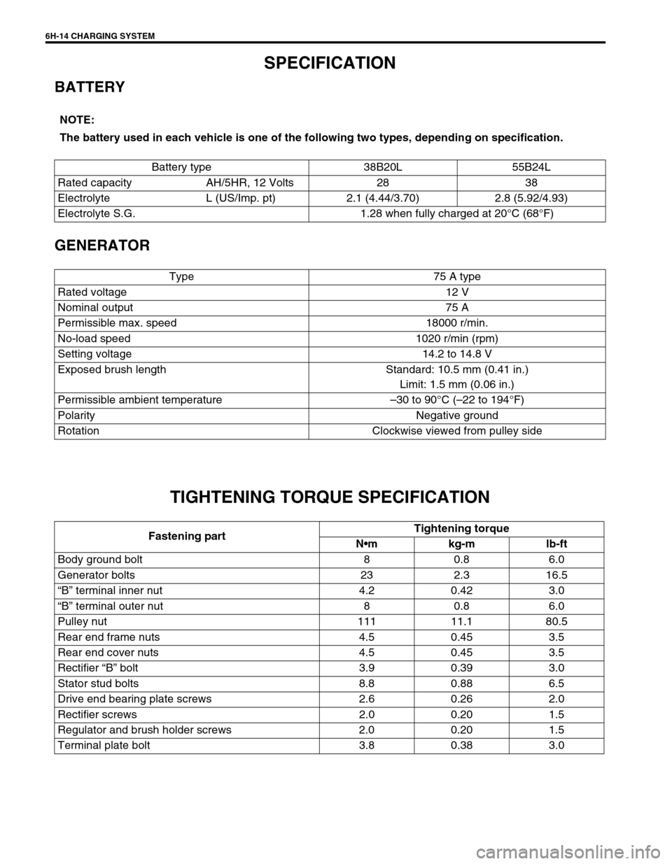
SPECIFICATION
BATTERY
GENERATOR
TIGHTENING TORQUE SPECIFICATION
NOTE:
The battery used in each vehicle is one of the following two types, depending on specification.
Battery type 38B20L 55B24L
Rated capacity AH/5HR, 12 Volts 28 38
Electrolyte L (US/Imp. pt) 2.1 (4.44/3.70) 2.8 (5.92/4.93)
Electrolyte S.G. 1.28 when fully charged at 20°C (68°F)
Type 75 A type
Rated voltage 12 V
Nominal output 75 A
Permissible max. speed 18000 r/min.
No-load speed 1020 r/min (rpm)
Setting voltage 14.2 to 14.8 V
Exposed brush length Standard: 10.5 mm (0.41 in.)
Limit: 1.5 mm (0.06 in.)
Permissible ambient temperature–30 to 90°C (–22 to 194°F)
Polarity Negative ground
Rotation Clockwise viewed from pulley side
Fastening partTightening torque
Nm kg-m lb-ft
Body ground bolt 8 0.8 6.0
Generator bolts 23 2.3 16.5
“B” terminal inner nut 4.2 0.42 3.0
“B” terminal outer nut 8 0.8 6.0
Pulley nut 111 11.1 80.5
Rear end frame nuts 4.5 0.45 3.5
Rear end cover nuts 4.5 0.45 3.5
Rectifier “B” bolt 3.9 0.39 3.0
Stator stud bolts 8.8 0.88 6.5
Drive end bearing plate screws 2.6 0.26 2.0
Rectifier screws 2.0 0.20 1.5
Regulator and brush holder screws 2.0 0.20 1.5
Terminal plate bolt 3.8 0.38 3.0