Page 617 of 698
6C-10 ENGINE FUEL
5) Connect fuel feed hose (1) and vapor hose (2) to each pipe
as shown in figure and clamp them securely.
6) Connect negative cable at battery.
With engine OFF, turn ignition switch to ON position and
check for fuel leaks.
FUEL PUMP ASSEMBLY
REMOVAL
1) Remove fuel tank from vehicle. Refer to “FUEL TANK”.
2) Disconnect fuel breather hose (1), fuel vapor hose (2) and
pipes from fuel pump assembly.
When disconnecting joint of fuel feed line (3) from pipe,
unlock joint by inserting special tool between pipe and joint
lock first.
Special tool
(A) : 09919-47020 CAUTION:
When connecting joint, clean outside surfaces of pipe
where joint is to be inserted, push joint into pipe till
joint lock clicks and check to ensure that pipes are
connected securely, or fuel leak may occur.
Never let the fuel hoses touch the ABS sensor harness
(if equipped).
WARNING:
Refer to the PRECAUTIONS at the beginning of ON-VEHI-
CLE SERVICE.
1
23
Page 618 of 698
ENGINE FUEL 6C-11
3) Remove fuel pump assembly (1) from fuel tank (2).
INSPECTION
Check fuel pump assembly for damage.
Check fuel suction filter (1) for evidence of dirt and contami-
nation.
If present, replace or clean and check for presence of dirt in
fuel tank.
For operation or electrical circuit inspection by referring to
Section 6E1.
For inspection of fuel level gauge (2) by referring to Section
8.
Check tank pressure control valve referring to the following
procedures.
a) Air should pass through valve (2) smoothly from fuel vapor
line hose (3) “A” to “B” when blown hard.
b) Also, when vacuum pump (4) is connected to fuel vapor
hose and pump air through valve, air should pass from “B”
to “A”.
Special tool
(A) : 09917-47910
If air doesn’t pass through valve in Step a) or vacuum is main-
tained in Step b), replace fuel filter assembly (1).
1
2
WARNING:
Do not such air through fuel vapor line hose. Fuel vapor
inside valve is harmful.12
Page 619 of 698
6C-12 ENGINE FUEL
DISASSEMBLY AND REASSEMBLY
Disassemble and reassemble fuel pump assembly, noting the fol-
lowings.
When removing fuel level sensor (3), press snap-fit part (4)
and slide it in the arrow direction as shown in figure.
When installing fuel level sensor to housing, fit fuel level sen-
sor securely.
“A” : Apply oil 5. O-ring 10. Fuel pressure regulator
1. Fuel filter assembly (including check valve) 6. Fuel level sensor (Fuel sender gauge) 11. Gasket
2. Grommet 7. Fuel pump 12. Fuel pump plate
3. Tube 8. Cushion Do not reuse.
4. Housing 9. Bracket
CAUTION:
While removing fuel level gauge, do not contact resis-
tor plate (1) or deform arm (2). It may cause fuel level
gauge to fail.
When removing grommet from fuel tube or bracket sub
assembly, be very careful not to cause damage to
grommet installed section (sealed section in bore).
Should it be damaged, replace it with new one, or fuel
will leak from that part.
Page 620 of 698
ENGINE FUEL 6C-13
INSTALLATION
1) Clean mating surfaces of fuel pump assembly (1) and fuel
tank.
2) Put plate (2) on fuel pump assembly (1) by matching the pro-
trusion of fuel pump assembly (3) to plate hole (4) as shown.
3) Install new gasket (2) and fuel pump assembly (1) with plate
(3) to fuel tank.
Tightening torque
Fuel pump assembly bolts (a) : 10 N·m (1.0 kg-m, 7.5 lb-ft)
4) Connect fuel breather hose (1), fuel vapor hose (2) and fuel
feed line (3) (pipe joint) to fuel pump assembly.
5) Install fuel tank (1) to vehicle. Refer to “FUEL TANK” in this
section.
3 2
4 43
1
3
1
2
(a)
CAUTION:
When connecting joint, clean outside surface of pipe
where joint is to be inserted, push joint into pipe till joint
lock clicks and check to ensure that pipes are connected
securely, or fuel leak may occur.1
23
Page 636 of 698

ENGINE AND EMISSION CONTROL SYSTEM 6E1-15
ON-VEHICLE SERVICE
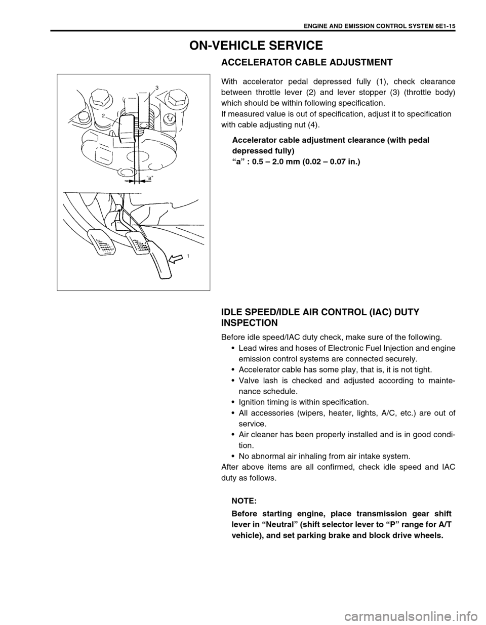
ACCELERATOR CABLE ADJUSTMENT
With accelerator pedal depressed fully (1), check clearance
between throttle lever (2) and lever stopper (3) (throttle body)
which should be within following specification.
If measured value is out of specification, adjust it to specification
with cable adjusting nut (4).
Accelerator cable adjustment clearance (with pedal
depressed fully)
“a” : 0.5 – 2.0 mm (0.02 – 0.07 in.)
IDLE SPEED/IDLE AIR CONTROL (IAC) DUTY
INSPECTION
Before idle speed/IAC duty check, make sure of the following.
Lead wires and hoses of Electronic Fuel Injection and engine
emission control systems are connected securely.
Accelerator cable has some play, that is, it is not tight.
Valve lash is checked and adjusted according to mainte-
nance schedule.
Ignition timing is within specification.
All accessories (wipers, heater, lights, A/C, etc.) are out of
service.
Air cleaner has been properly installed and is in good condi-
tion.
No abnormal air inhaling from air intake system.
After above items are all confirmed, check idle speed and IAC
duty as follows.
NOTE:
Before starting engine, place transmission gear shift
lever in “Neutral” (shift selector lever to “P” range for A/T
vehicle), and set parking brake and block drive wheels.
Page 637 of 698

6E1-16 ENGINE AND EMISSION CONTROL SYSTEM
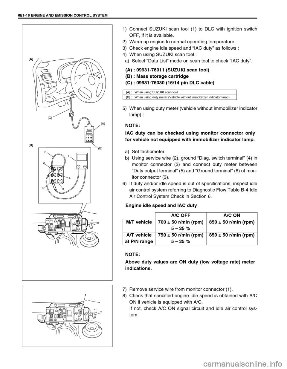
1) Connect SUZUKI scan tool (1) to DLC with ignition switch
OFF, if it is available.
2) Warm up engine to normal operating temperature.
3) Check engine idle speed and “IAC duty” as follows :
4) When using SUZUKI scan tool :
a) Select “Data List” mode on scan tool to check “IAC duty”.
(A) : 09931-76011 (SUZUKI scan tool)
(B) : Mass storage cartridge
(C) : 09931-76030 (16/14 pin DLC cable)
5) When using duty meter (vehicle without immobilizer indicator
lamp) :
a) Set tachometer.
b) Using service wire (2), ground “Diag. switch terminal” (4) in
monitor connector (3) and connect duty meter between
“Duty output terminal” (5) and “Ground terminal” (6) of mon-
itor connector (3).
6) If duty and/or idle speed is out of specifications, inspect idle
air control system referring to Diagnostic Flow Table B-4 Idle
Air Control System Check in Section 6.
Engine idle speed and IAC duty
7) Remove service wire from monitor connector (1).
8) Check that specified engine idle speed is obtained with A/C
ON if vehicle is equipped with A/C.
If not, check A/C ON signal circuit and idle air control sys-
tem.
[A] : When using SUZUKI scan tool
[B] : When using duty meter (Vehicle without immobilizer indicator lamp)
NOTE:
IAC duty can be checked using monitor connector only
for vehicle not equipped with immobilizer indicator lamp.
A/C OFF A/C ON
M/T vehicle 700 ± 50 r/min (rpm)
5 – 25 %850 ± 50 r/min (rpm)
A/T vehicle
at P/N range750 ± 50 r/min (rpm)
5 – 25 %850 ± 50 r/min (rpm)
NOTE:
Above duty values are ON duty (low voltage rate) meter
indications.
(C)
(A)
(B)
1 2
6
54
3-+
[A]
[B]
1
Page 638 of 698

ENGINE AND EMISSION CONTROL SYSTEM 6E1-17
IDLE MIXTURE INSPECTION / ADJUSTMENT (VEHI-
CLE WITHOUT HEATED OXYGEN SENSOR)
All vehicles not equipped with heated oxygen sensor are shipped
with their CO % factory adjusted as follows.
Engine idle mixture (CO %)
0.5 – 1.5 % at specified idle speed
Idle mixture adjustment should never be changed from the origi-
nal factory setting. However, if during diagnosis, the check indi-
cates idle mixture to be the cause of a driver performance
complaint or emission failure, the idle mixture can be adjusted
using the following procedures.
1) Check idle speed according to “Idle Speed Inspection” sec-
tion.
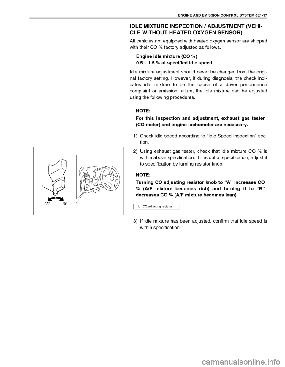
2) Using exhaust gas tester, check that idle mixture CO % is
within above specification. If it is out of specification, adjust it
to specification by turning resistor knob.
3) If idle mixture has been adjusted, confirm that idle speed is
within specification. NOTE:
For this inspection and adjustment, exhaust gas tester
(CO meter) and engine tachometer are necessary.
NOTE:
Turning CO adjusting resistor knob to “A” increases CO
% (A/F mixture becomes rich) and turning it to “B”
decreases CO % (A/F mixture becomes lean).
1. CO adjusting resistor
Page 639 of 698
6E1-18 ENGINE AND EMISSION CONTROL SYSTEM
AIR INTAKE SYSTEM
THROTTLE BODY
ON-VEHICLE INSPECTION
Check that throttle valve lever (1) moves smoothly.
REMOVAL
1) Disconnect negative cable at battery.
2) Drain cooling system.
3) Disconnect accelerator cable (1) from throttle valve lever.
4) Disconnect IAT sensor connector and remove air cleaner
assembly with air cleaner outlet hose.
1. Throttle body 4. Gasket 7. TP sensor screws
2. Throttle stop screw 5. Idle air control valve Tightening torque
3. TP sensor 6. IAC valve screws Do not reuse.