Page 601 of 698
6B-12 ENGINE COOLING
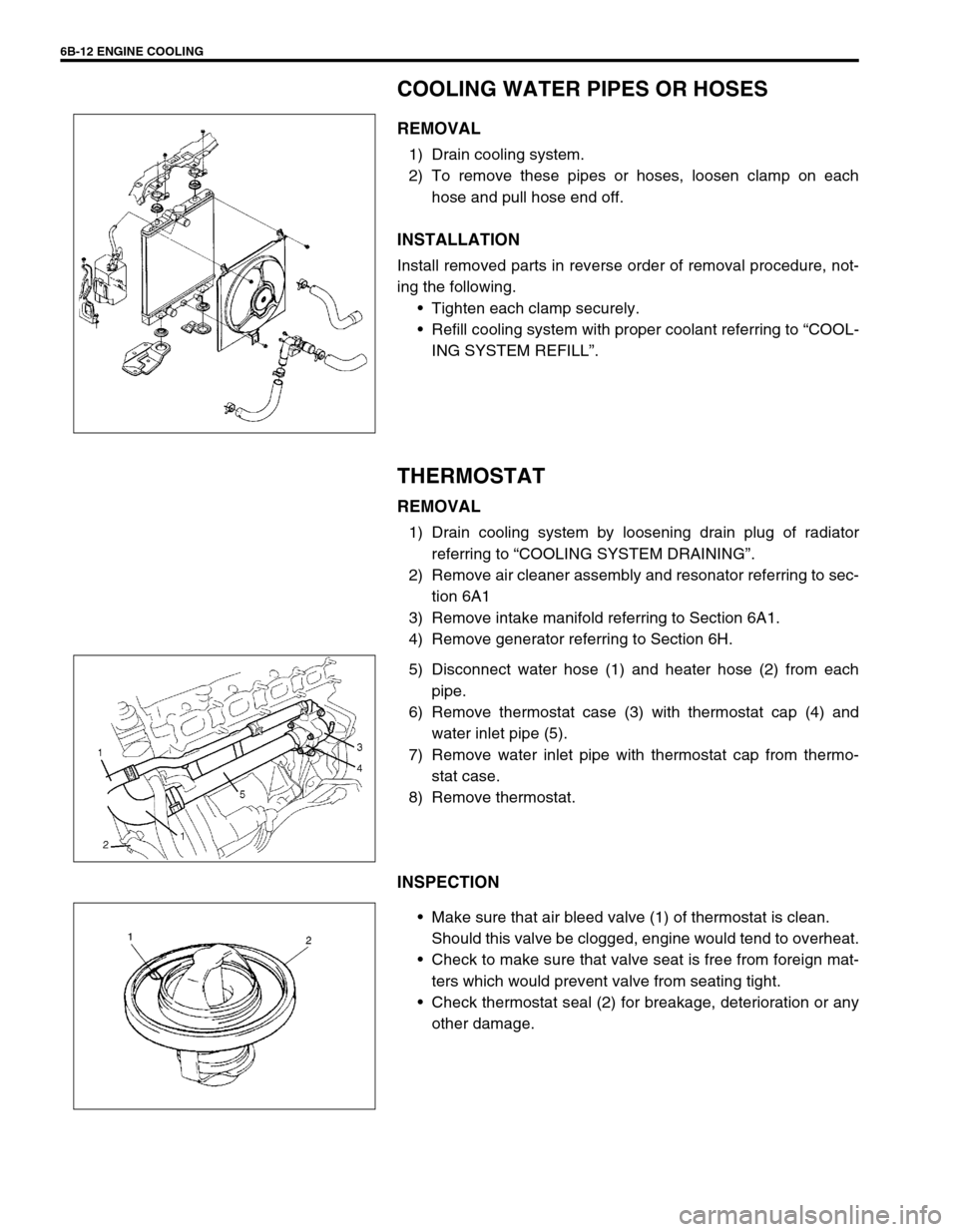
COOLING WATER PIPES OR HOSES
REMOVAL
1) Drain cooling system.
2) To remove these pipes or hoses, loosen clamp on each
hose and pull hose end off.
INSTALLATION
Install removed parts in reverse order of removal procedure, not-
ing the following.
Tighten each clamp securely.
Refill cooling system with proper coolant referring to “COOL-
ING SYSTEM REFILL”.
THERMOSTAT
REMOVAL
1) Drain cooling system by loosening drain plug of radiator
referring to “COOLING SYSTEM DRAINING”.
2) Remove air cleaner assembly and resonator referring to sec-
tion 6A1
3) Remove intake manifold referring to Section 6A1.
4) Remove generator referring to Section 6H.
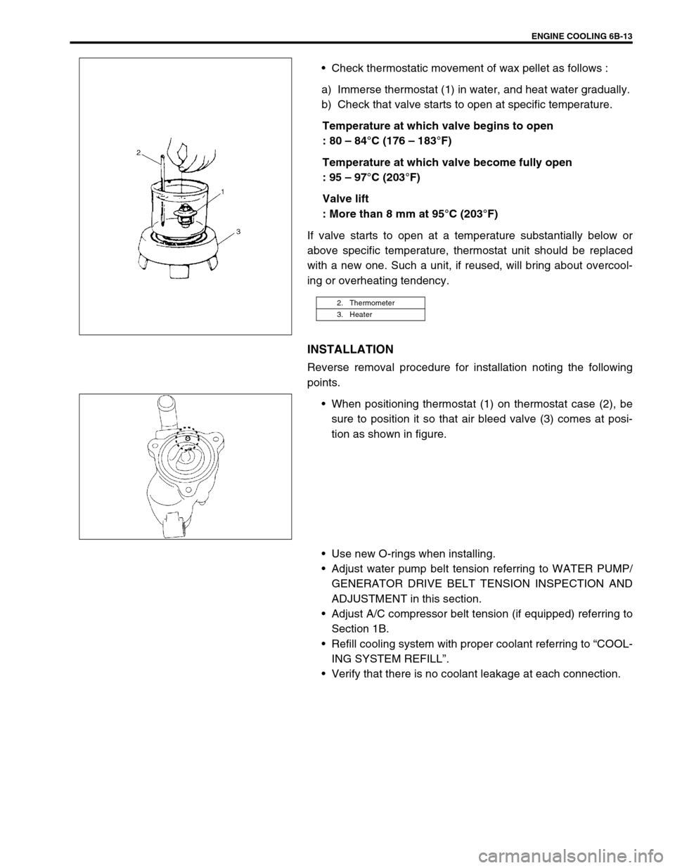
5) Disconnect water hose (1) and heater hose (2) from each
pipe.
6) Remove thermostat case (3) with thermostat cap (4) and
water inlet pipe (5).
7) Remove water inlet pipe with thermostat cap from thermo-
stat case.
8) Remove thermostat.
INSPECTION
Make sure that air bleed valve (1) of thermostat is clean.
Should this valve be clogged, engine would tend to overheat.
Check to make sure that valve seat is free from foreign mat-
ters which would prevent valve from seating tight.
Check thermostat seal (2) for breakage, deterioration or any
other damage.
Page 602 of 698
ENGINE COOLING 6B-13
Check thermostatic movement of wax pellet as follows :
a) Immerse thermostat (1) in water, and heat water gradually.
b) Check that valve starts to open at specific temperature.
Temperature at which valve begins to open
: 80 – 84°C (176 – 183°F)
Temperature at which valve become fully open
: 95 – 97°C (203°F)
Valve lift
: More than 8 mm at 95°C (203°F)
If valve starts to open at a temperature substantially below or
above specific temperature, thermostat unit should be replaced
with a new one. Such a unit, if reused, will bring about overcool-
ing or overheating tendency.
INSTALLATION
Reverse removal procedure for installation noting the following
points.
When positioning thermostat (1) on thermostat case (2), be
sure to position it so that air bleed valve (3) comes at posi-
tion as shown in figure.
Use new O-rings when installing.
Adjust water pump belt tension referring to WATER PUMP/
GENERATOR DRIVE BELT TENSION INSPECTION AND
ADJUSTMENT in this section.
Adjust A/C compressor belt tension (if equipped) referring to
Section 1B.
Refill cooling system with proper coolant referring to “COOL-
ING SYSTEM REFILL”.
Verify that there is no coolant leakage at each connection.
2. Thermometer
3. Heater
Page 603 of 698
6B-14 ENGINE COOLING
RADIATOR
REMOVAL
1) Disconnect negative cable at battery.
2) Drain cooling system by loosening drain plug of radiator.
Refer to “COOLING SYSTEM DRAINING”.
3) Disconnect connector of cooling fan motor.
4) Remove air cleaner inlet hose (1) and suction pipe (2).
5) Remove reservoir tank (1) and then its bracket (2).
6) Disconnect radiator inlet and outlet hoses from radiator.
7) Remove cooling fan assembly (3).
8) Remove radiator.
INSPECTION
Check radiator for leakage or damage. Straighten bent fins, if
any.
CLEANING
Clean frontal area of radiator cores.
INSTALLATION
Reverse removal procedures, noting the followings.
Refill cooling system with proper coolant referring to “COOL-
ING SYSTEM REFILL”.
After installation, check each joint for leakage.
Page 604 of 698
ENGINE COOLING 6B-15
RADIATOR AND CONDENSER COOLING FAN
Refer to “RADIATOR AND CONDENSER COOLING FAN” in
Section 1B for removal, inspection and installation.
RADIATOR AND CONDENSER COOLING FAN
RELAY
INSPECTION
1) Disconnect negative (–) cable at battery.
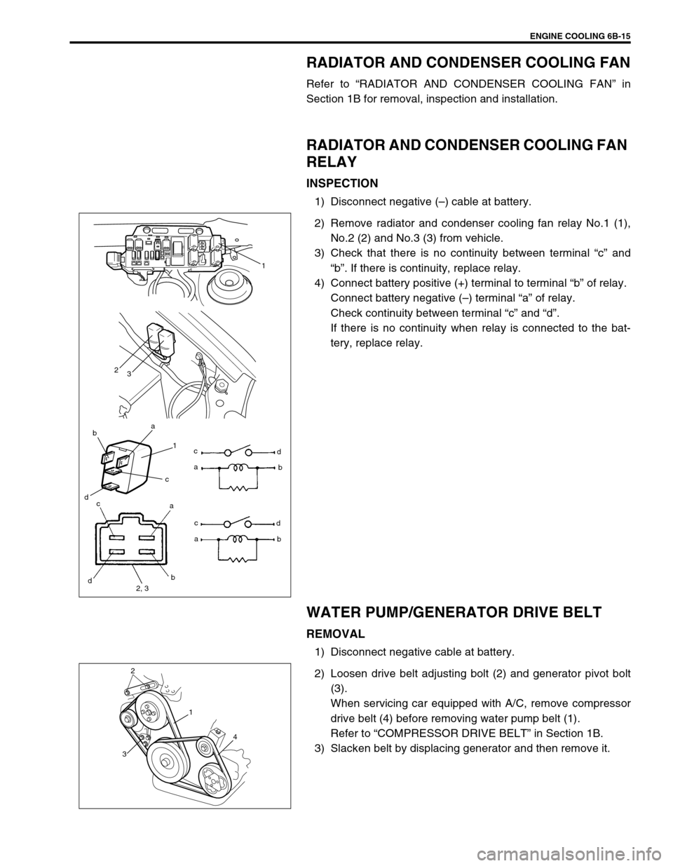
2) Remove radiator and condenser cooling fan relay No.1 (1),
No.2 (2) and No.3 (3) from vehicle.
3) Check that there is no continuity between terminal “c” and
“b”. If there is continuity, replace relay.
4) Connect battery positive (+) terminal to terminal “b” of relay.
Connect battery negative (–) terminal “a” of relay.
Check continuity between terminal “c” and “d”.
If there is no continuity when relay is connected to the bat-
tery, replace relay.
WATER PUMP/GENERATOR DRIVE BELT
REMOVAL
1) Disconnect negative cable at battery.
2) Loosen drive belt adjusting bolt (2) and generator pivot bolt
(3).
When servicing car equipped with A/C, remove compressor
drive belt (4) before removing water pump belt (1).
Refer to “COMPRESSOR DRIVE BELT” in Section 1B.
3) Slacken belt by displacing generator and then remove it.
ba
1
c
dc
ad
b
2
3
1
c
d
2, 3b a
ac
d
b
2
3
1
4
Page 606 of 698
ENGINE COOLING 6B-17
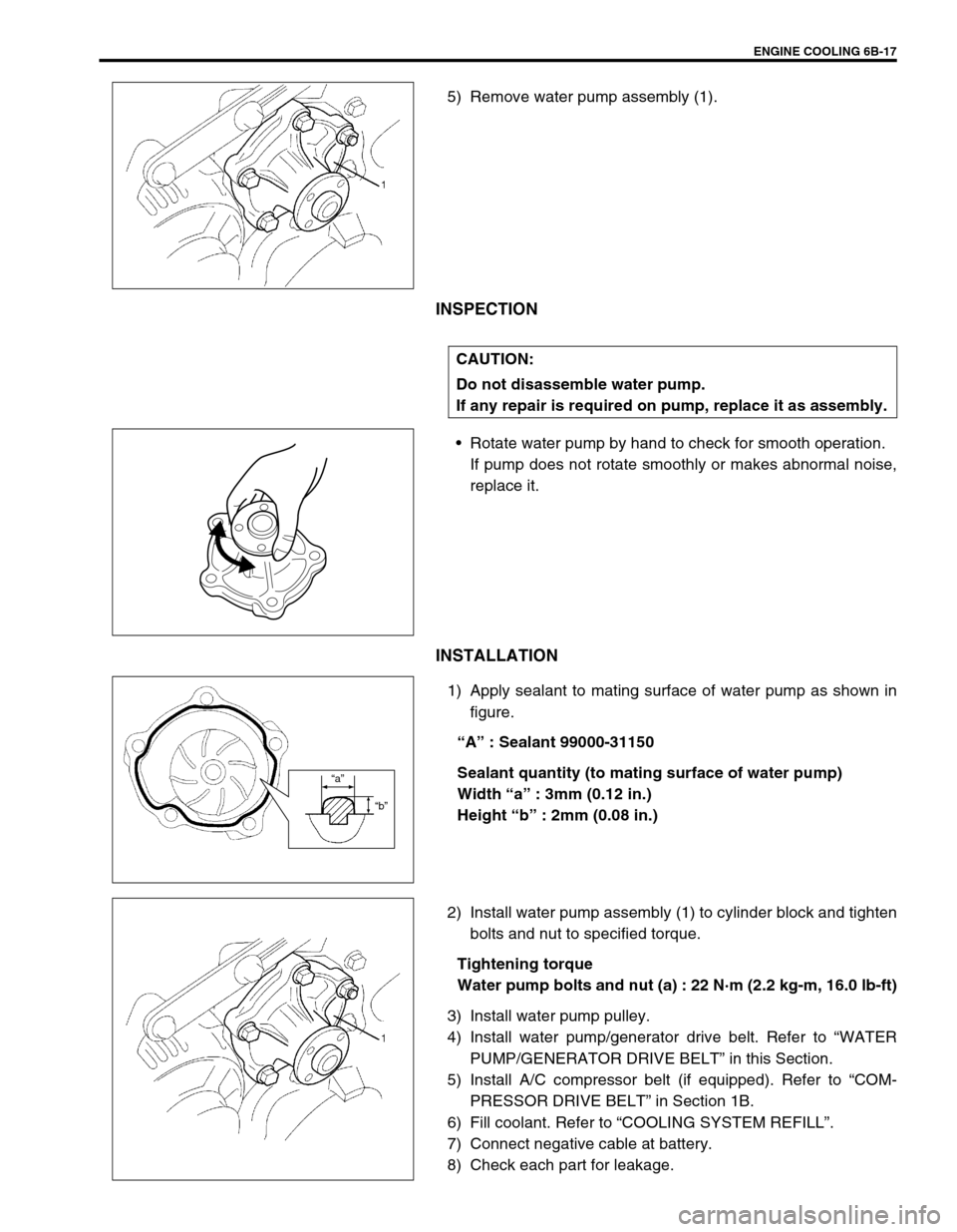
5) Remove water pump assembly (1).
INSPECTION
Rotate water pump by hand to check for smooth operation.
If pump does not rotate smoothly or makes abnormal noise,
replace it.
INSTALLATION
1) Apply sealant to mating surface of water pump as shown in
figure.
“A” : Sealant 99000-31150
Sealant quantity (to mating surface of water pump)
Width “a” : 3mm (0.12 in.)
Height “b” : 2mm (0.08 in.)
2) Install water pump assembly (1) to cylinder block and tighten
bolts and nut to specified torque.
Tightening torque
Water pump bolts and nut (a) : 22 N·m (2.2 kg-m, 16.0 lb-ft)
3) Install water pump pulley.
4) Install water pump/generator drive belt. Refer to “WATER
PUMP/GENERATOR DRIVE BELT” in this Section.
5) Install A/C compressor belt (if equipped). Refer to “COM-
PRESSOR DRIVE BELT” in Section 1B.
6) Fill coolant. Refer to “COOLING SYSTEM REFILL”.
7) Connect negative cable at battery.
8) Check each part for leakage.
CAUTION:
Do not disassemble water pump.
If any repair is required on pump, replace it as assembly.
“a”
“b”
Page 612 of 698
ENGINE FUEL 6C-5
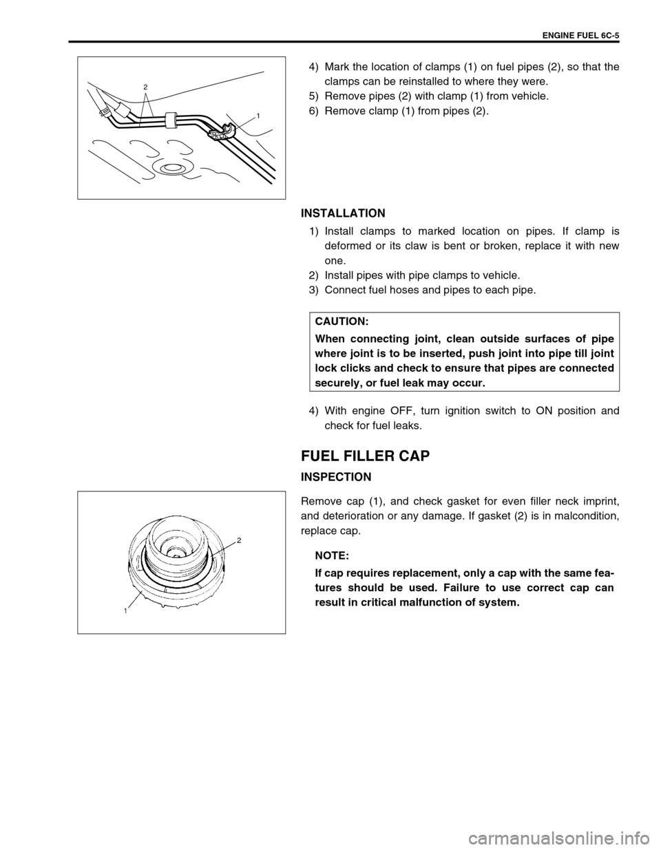
4) Mark the location of clamps (1) on fuel pipes (2), so that the
clamps can be reinstalled to where they were.
5) Remove pipes (2) with clamp (1) from vehicle.
6) Remove clamp (1) from pipes (2).
INSTALLATION
1) Install clamps to marked location on pipes. If clamp is
deformed or its claw is bent or broken, replace it with new
one.
2) Install pipes with pipe clamps to vehicle.
3) Connect fuel hoses and pipes to each pipe.
4) With engine OFF, turn ignition switch to ON position and
check for fuel leaks.
FUEL FILLER CAP
INSPECTION
Remove cap (1), and check gasket for even filler neck imprint,
and deterioration or any damage. If gasket (2) is in malcondition,
replace cap.
2
1
CAUTION:
When connecting joint, clean outside surfaces of pipe
where joint is to be inserted, push joint into pipe till joint
lock clicks and check to ensure that pipes are connected
securely, or fuel leak may occur.
NOTE:
If cap requires replacement, only a cap with the same fea-
tures should be used. Failure to use correct cap can
result in critical malfunction of system.
Page 613 of 698
6C-6 ENGINE FUEL
FUEL TANK INLET VALVE
REMOVAL
1) Remove fuel filler cap.
2) Insert hose of a hand operated pump into fuel filler hose (1)
and drain fuel in space “A” in the figure.
3) Hoist vehicle and remove clamp (2) and fuel filler hose (1)
from fuel tank.
4) Remove fuel tank inlet valve (1) using flat-bladed screw-
driver.
INSPECTION
Check fuel tank inlet valve for the followings.
Damage
Smooth opening and closing
If any damage or malfunction is found, replace.WARNING:
Refer to the WARNING at the beginning of ON-VEHICLE
SERVICE in this section.
CAUTION:
Do not force pump hose into fuel tank, or pump hose
may damage fuel tank inlet valve (2).
1
2
CAUTION:
Be careful not to damage fuel tank inlet valve (1) with flat-
bladed screwdriver.
Page 615 of 698
6C-8 ENGINE FUEL
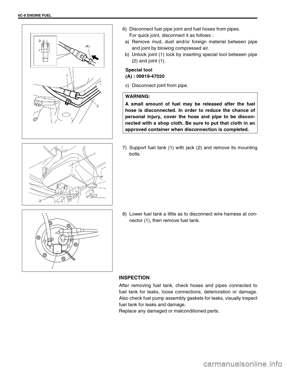
6) Disconnect fuel pipe joint and fuel hoses from pipes.
For quick joint, disconnect it as follows :
a) Remove mud, dust and/or foreign material between pipe
and joint by blowing compressed air.
b) Unlock joint (1) lock by inserting special tool between pipe
(2) and joint (1).
Special tool
(A) : 09919-47020
c) Disconnect joint from pipe.
7) Support fuel tank (1) with jack (2) and remove its mounting
bolts.
8) Lower fuel tank a little as to disconnect wire harness at con-
nector (1), then remove fuel tank.
INSPECTION
After removing fuel tank, check hoses and pipes connected to
fuel tank for leaks, loose connections, deterioration or damage.
Also check fuel pump assembly gaskets for leaks, visually inspect
fuel tank for leaks and damage.
Replace any damaged or malconditioned parts.WARNING:
A small amount of fuel may be released after the fuel
hose is disconnected. In order to reduce the chance of
personal injury, cover the hose and pipe to be discon-
nected with a shop cloth. Be sure to put that cloth in an
approved container when disconnection is completed.
1