Page 585 of 698
6A1-84 ENGINE MECHANICAL (M13 ENGINE)
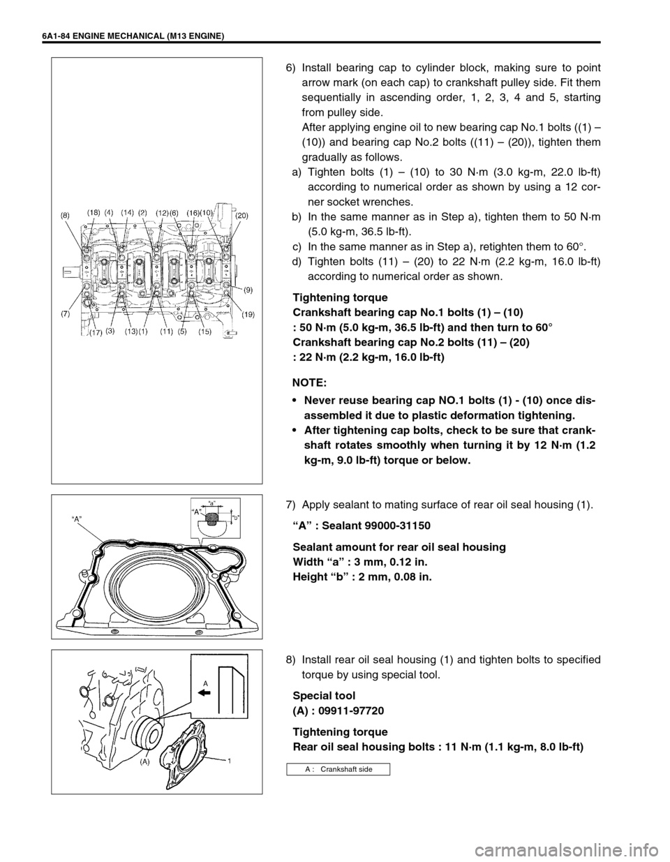
6) Install bearing cap to cylinder block, making sure to point
arrow mark (on each cap) to crankshaft pulley side. Fit them
sequentially in ascending order, 1, 2, 3, 4 and 5, starting
from pulley side.
After applying engine oil to new bearing cap No.1 bolts ((1) –
(10)) and bearing cap No.2 bolts ((11) – (20)), tighten them
gradually as follows.
a) Tighten bolts (1) – (10) to 30 N·m (3.0 kg-m, 22.0 lb-ft)
according to numerical order as shown by using a 12 cor-
ner socket wrenches.
b) In the same manner as in Step a), tighten them to 50 N·m
(5.0 kg-m, 36.5 lb-ft).
c) In the same manner as in Step a), retighten them to 60°.
d) Tighten bolts (11) – (20) to 22 N·m (2.2 kg-m, 16.0 lb-ft)
according to numerical order as shown.
Tightening torque
Crankshaft bearing cap No.1 bolts (1) – (10)
: 50 N·m (5.0 kg-m, 36.5 lb-ft) and then turn to 60°
Crankshaft bearing cap No.2 bolts (11) – (20)
: 22 N·m (2.2 kg-m, 16.0 lb-ft)
7) Apply sealant to mating surface of rear oil seal housing (1).
“A” : Sealant 99000-31150
Sealant amount for rear oil seal housing
Width “a” : 3 mm, 0.12 in.
Height “b” : 2 mm, 0.08 in.
8) Install rear oil seal housing (1) and tighten bolts to specified
torque by using special tool.
Special tool
(A) : 09911-97720
Tightening torque
Rear oil seal housing bolts : 11 N·m (1.1 kg-m, 8.0 lb-ft) NOTE:
Never reuse bearing cap NO.1 bolts (1) - (10) once dis-
assembled it due to plastic deformation tightening.
After tightening cap bolts, check to be sure that crank-
shaft rotates smoothly when turning it by 12 N·m (1.2
kg-m, 9.0 lb-ft) torque or below.
A : Crankshaft side
Page 590 of 698
ENGINE COOLING 6B-1
6B
SECTION 6B
ENGINE COOLING
CONTENTS
GENERAL DESCRIPTION ...............................6B-2
COOLING SYSTEM CIRCULATION............. 6B-2
COOLANT ..................................................... 6B-3
DIAGNOSIS ......................................................6B-4
DIAGNOSIS TABLE ...................................... 6B-4
SYSTEM CIRCUIT ........................................ 6B-5
SYSTEM CIRCUIT INSPECTION ................. 6B-5
MAINTENANCE................................................6B-6
COOLANT LEVEL CHECK ........................... 6B-6
ENGINE COOLING SYSTEM
INSPECTION AND SERVICE ....................... 6B-7
COOLING SYSTEM FLUSH AND REFILL ... 6B-7
WATER PUMP/GENERATOR DRIVE
BELT TENSION INSPECTION AND
ADJUSTMENT .............................................. 6B-9
ON-VEHICLE SERVICE .................................6B-10SYSTEM COMPONENTS .......................... 6B-10
COOLING SYSTEM DRAINING ................. 6B-11
COOLING SYSTEM REFILL ...................... 6B-11
COOLING WATER PIPES OR HOSES ...... 6B-12
THERMOSTAT ........................................... 6B-12
RADIATOR ................................................. 6B-14
RADIATOR AND CONDENSER
COOLING FAN ........................................... 6B-15
RADIATOR AND CONDENSER
COOLING FAN RELAY .............................. 6B-15
WATER PUMP/GENERATOR
DRIVE BELT ............................................... 6B-15
WATER PUMP............................................ 6B-16
ECT SENSOR............................................. 6B-18
REQUIRED SERVICE MATERIAL................. 6B-18
TIGHTENING TORQUE SPECIFICATION..... 6B-18
Page 593 of 698
6B-4 ENGINE COOLING
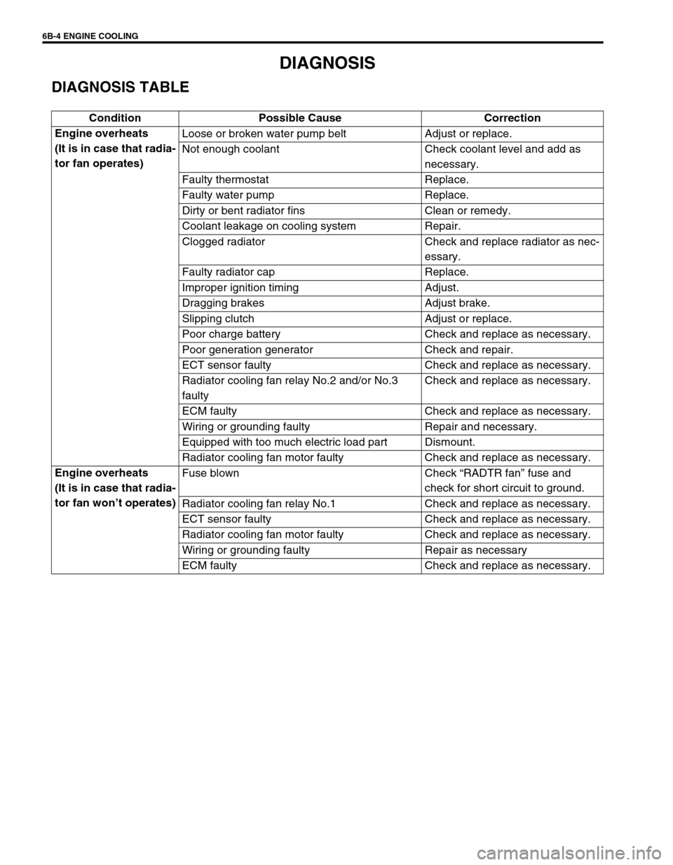
DIAGNOSIS
DIAGNOSIS TABLE
Condition Possible Cause Correction
Engine overheats
(It is in case that radia-
tor fan operates)Loose or broken water pump belt Adjust or replace.
Not enough coolant Check coolant level and add as
necessary.
Faulty thermostat Replace.
Faulty water pump Replace.
Dirty or bent radiator fins Clean or remedy.
Coolant leakage on cooling system Repair.
Clogged radiator Check and replace radiator as nec-
essary.
Faulty radiator cap Replace.
Improper ignition timing Adjust.
Dragging brakes Adjust brake.
Slipping clutch Adjust or replace.
Poor charge battery Check and replace as necessary.
Poor generation generator Check and repair.
ECT sensor faulty Check and replace as necessary.
Radiator cooling fan relay No.2 and/or No.3
faultyCheck and replace as necessary.
ECM faulty Check and replace as necessary.
Wiring or grounding faulty Repair and necessary.
Equipped with too much electric load part Dismount.
Radiator cooling fan motor faulty Check and replace as necessary.
Engine overheats
(It is in case that radia-
tor fan won’t operates)Fuse blown Check “RADTR fan” fuse and
check for short circuit to ground.
Radiator cooling fan relay No.1 Check and replace as necessary.
ECT sensor faulty Check and replace as necessary.
Radiator cooling fan motor faulty Check and replace as necessary.
Wiring or grounding faulty Repair as necessary
ECM faulty Check and replace as necessary.
Page 594 of 698
ENGINE COOLING 6B-5
SYSTEM CIRCUIT
SYSTEM CIRCUIT INSPECTION
Refer to “RADIATOR COOLINGFAN CONTROL SYSTEM CHECK” in Section 6
1. Main fuse box 6. ECM main fuse 11. Radiator and condenser cooling fan motor
2. Generator 7. ECM main relay 12. Refrigerant pressure triple switch (if equipped with A/C)
3. Battery 8. Radiator and condenser cooling fan relay No.1 13. ECT sensor
4. Battery fuse 9. Radiator and condenser cooling fan relay No.2 14. ECM
5. RADTR fuse 10. Radiator and condenser cooling fan relay No.3 15. TO A/C switch
ACG
15A 30A
BLU/WHT
BLK/YEL
BLK
BLU
ORN
BLK
BLK
BLUH–
H+
L– L+
GRN/BLK
BLU/BLK
BRN/WHT
YEL/GRN
PNK/GRN
PPL/YEL
LT GRN/BLK
BLK/RED
BLK/RED 80A
145
6
2
3
7
8
9
11
10
13 15
12
14
Page 595 of 698
6B-6 ENGINE COOLING
MAINTENANCE
COOLANT LEVEL CHECK
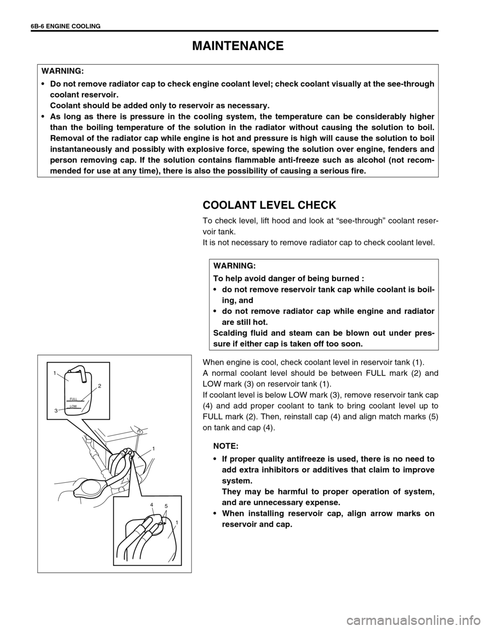
To check level, lift hood and look at “see-through” coolant reser-
voir tank.
It is not necessary to remove radiator cap to check coolant level.
When engine is cool, check coolant level in reservoir tank (1).
A normal coolant level should be between FULL mark (2) and
LOW mark (3) on reservoir tank (1).
If coolant level is below LOW mark (3), remove reservoir tank cap
(4) and add proper coolant to tank to bring coolant level up to
FULL mark (2). Then, reinstall cap (4) and align match marks (5)
on tank and cap (4). WARNING:
Do not remove radiator cap to check engine coolant level; check coolant visually at the see-through
coolant reservoir.
Coolant should be added only to reservoir as necessary.
As long as there is pressure in the cooling system, the temperature can be considerably higher
than the boiling temperature of the solution in the radiator without causing the solution to boil.
Removal of the radiator cap while engine is hot and pressure is high will cause the solution to boil
instantaneously and possibly with explosive force, spewing the solution over engine, fenders and
person removing cap. If the solution contains flammable anti-freeze such as alcohol (not recom-
mended for use at any time), there is also the possibility of causing a serious fire.
WARNING:
To help avoid danger of being burned :
do not remove reservoir tank cap while coolant is boil-
ing, and
do not remove radiator cap while engine and radiator
are still hot.
Scalding fluid and steam can be blown out under pres-
sure if either cap is taken off too soon.
NOTE:
If proper quality antifreeze is used, there is no need to
add extra inhibitors or additives that claim to improve
system.
They may be harmful to proper operation of system,
and are unnecessary expense.
When installing reservoir cap, align arrow marks on
reservoir and cap.
LOW FULL
5 41
1 32 1
Page 596 of 698
ENGINE COOLING 6B-7
ENGINE COOLING SYSTEM INSPECTION
AND SERVICE
1) Check cooling system for leakage or damage.
2) Wash radiator cap and filler neck with clean water by remov-
ing radiator cap when engine is cold.
3) Check coolant for proper level and freeze protection.
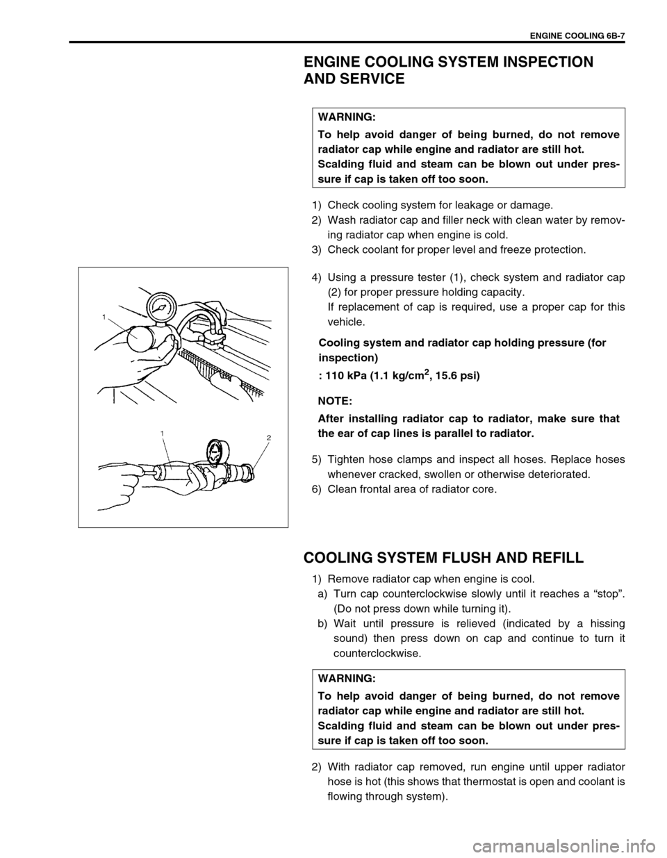
4) Using a pressure tester (1), check system and radiator cap
(2) for proper pressure holding capacity.
If replacement of cap is required, use a proper cap for this
vehicle.
Cooling system and radiator cap holding pressure (for
inspection)
: 110 kPa (1.1 kg/cm
2, 15.6 psi)
5) Tighten hose clamps and inspect all hoses. Replace hoses
whenever cracked, swollen or otherwise deteriorated.
6) Clean frontal area of radiator core.
COOLING SYSTEM FLUSH AND REFILL
1) Remove radiator cap when engine is cool.
a) Turn cap counterclockwise slowly until it reaches a “stop”.
(Do not press down while turning it).
b) Wait until pressure is relieved (indicated by a hissing
sound) then press down on cap and continue to turn it
counterclockwise.
2) With radiator cap removed, run engine until upper radiator
hose is hot (this shows that thermostat is open and coolant is
flowing through system). WARNING:
To help avoid danger of being burned, do not remove
radiator cap while engine and radiator are still hot.
Scalding fluid and steam can be blown out under pres-
sure if cap is taken off too soon.
NOTE:
After installing radiator cap to radiator, make sure that
the ear of cap lines is parallel to radiator.
WARNING:
To help avoid danger of being burned, do not remove
radiator cap while engine and radiator are still hot.
Scalding fluid and steam can be blown out under pres-
sure if cap is taken off too soon.
Page 598 of 698
ENGINE COOLING 6B-9
WATER PUMP/GENERATOR DRIVE BELT TENSION INSPECTION AND
ADJUSTMENT
1) Inspect belt for cracks, cuts, deformation, wear and cleanli-
ness. If it is necessary to replace belt, refer to “WATER
PUMP/GENERATOR DRIVE BELT” in this section.
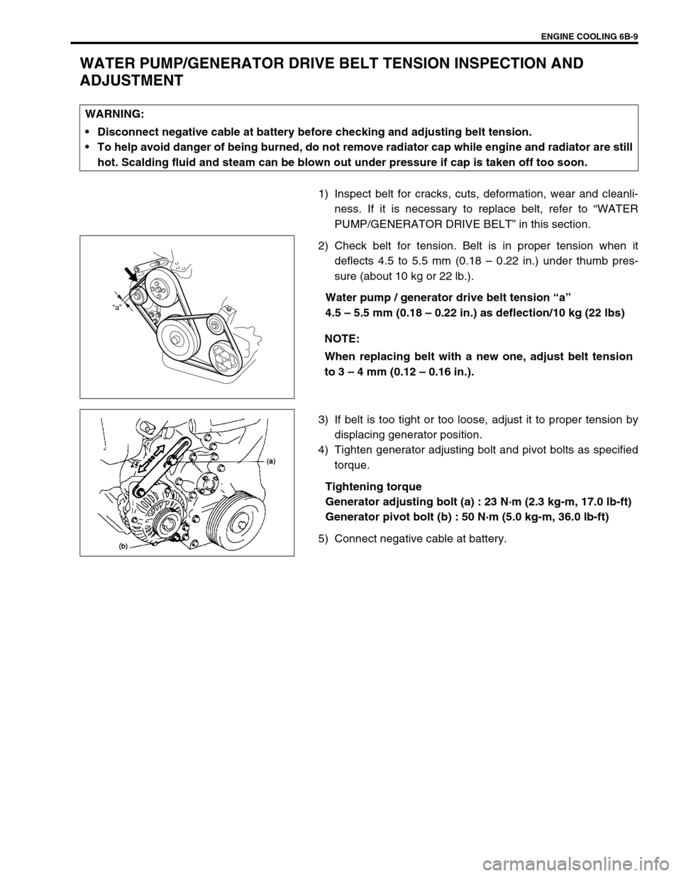
2) Check belt for tension. Belt is in proper tension when it
deflects 4.5 to 5.5 mm (0.18 – 0.22 in.) under thumb pres-
sure (about 10 kg or 22 lb.).
Water pump / generator drive belt tension “a”
4.5 – 5.5 mm (0.18 – 0.22 in.) as deflection/10 kg (22 lbs)
3) If belt is too tight or too loose, adjust it to proper tension by
displacing generator position.
4) Tighten generator adjusting bolt and pivot bolts as specified
torque.
Tightening torque
Generator adjusting bolt (a) : 23 N·m (2.3 kg-m, 17.0 lb-ft)
Generator pivot bolt (b) : 50 N·m (5.0 kg-m, 36.0 lb-ft)
5) Connect negative cable at battery. WARNING:
Disconnect negative cable at battery before checking and adjusting belt tension.
To help avoid danger of being burned, do not remove radiator cap while engine and radiator are still
hot. Scalding fluid and steam can be blown out under pressure if cap is taken off too soon.
NOTE:
When replacing belt with a new one, adjust belt tension
to 3 – 4 mm (0.12 – 0.16 in.).
“a”
Page 599 of 698
6B-10 ENGINE COOLING
ON-VEHICLE SERVICE
SYSTEM COMPONENTS
WARNING:
Check to make sure that engine coolant temperature is cold before removing any part of cooling
system.
Also be sure to disconnect negative cord from battery terminal before removing any part.
1. Radiator 11. To throttle body 21. To timing chain cover
2. Reservoir tank 12. To heater unit 22. O-Ring
3. Radiator cap 13. To water pump 23. Gasket
4. Drain plug 14. Radiator and condenser cooling fan assembly 24. Water outlet cap O-ring No.1
5. Radiator outlet hose 15. Water inlet pipe No.1 25. Water outlet cap O-ring No.2
6. Radiator inlet hose 16. Water inlet pipe No.2 26. Thermostat cap bolts
7. Thermostat 17. Thermostat cap 27. Thermostat case bolts
8. ECT sensor 18. Water outlet cap Tightening torque
9. Thermostat case 19. Heater inlet hose Do not reuse.
10. To cylinder head 20. Heater outlet hose