2000 SUZUKI SWIFT check engine
[x] Cancel search: check enginePage 4 of 698

GENERAL INFORMATION 0A-1
0A
6F2
6G
6H
6K
7A
7A1
7B1
7C1
7D
7E
7F
8A
8B
8C
8D
8E
9
10
10A
10B
SECTION 0A
GENERAL INFORMATION
CONTENTS
HOW TO USE THIS MANUAL .........................0A-2
PRECAUTIONS ................................................0A-3
PRECAUTION FOR VEHICLES EQUIPPED
WITH A SUPPLEMENTAL RESTRAINT
(AIR BAG) SYSTEM ..................................... 0A-3
DIAGNOSIS .............................................. 0A-3
SERVICING AND HANDLING .................. 0A-4
GENERAL PRECAUTIONS .......................... 0A-6
PRECAUTIONS FOR CATALYTIC
CONVERTER ................................................ 0A-9
PRECAUTION FOR INSTALLING MOBILE
COMMUNICATION EQUIPMENT ................. 0A-9
PRECAUTION IN SERVICING FULL-TIME
4WD VEHICLE ............................................ 0A-10
PRECAUTIONS FOR ELECTRICAL
CIRCUIT SERVICE ..................................... 0A-11
ELECTRICAL CIRCUIT INSPECTION
PROCEDURE ............................................. 0A-13
OPEN CIRCUIT CHECK ......................... 0A-13
CONTINUITY CHECK ............................. 0A-14
VOLTAGE CHECK .................................. 0A-15SHORT CIRCUIT CHECK (WIRE
HARNESS TO GROUND)....................... 0A-16
INTERMITTENT AND POOR
CONNECTION ............................................ 0A-16
IDENTIFICATION INFORMATION ................. 0A-18
VEHICLE IDENTIFICATION NUMBER ...... 0A-18
ENGINE IDENTIFICATION NUMBER ........ 0A-18
TRANSMISSION IDENTIFICATION
NUMBER .................................................... 0A-18
WARNING, CAUTION AND INFORMATION
LABELS.......................................................... 0A-19
VEHICLE LIFTING POINTS ........................... 0A-20
ABBREVIATIONS AND SYMBOLS MAY
BE USED IN THIS MANUAL.......................... 0A-22
FASTENER INFORMATION .......................... 0A-25
METRIC FASTENERS................................ 0A-25
FASTENER STRENGTH
IDENTIFICATION ....................................... 0A-25
STANDARD TIGHTENING TORQUE......... 0A-25
Page 9 of 698

0A-6 GENERAL INFORMATION
Air bag wire harness can be identified easily as it is covered with a yellow protection tube. Be very
careful when handling it.
When an open in air bag wire harness, damaged wire harness, connector or terminal is found,
replace wire harness, connectors and terminals as an assembly.
Do not apply power to the air bag system unless all components are connected or a diagnostic chart
requests it, as this will set a diagnostic trouble code.
Never use air bag system component parts from another vehicle.
When using electric welding, be sure to temporarily disable air bag system referring to “DISABLING
AIR BAG SYSTEM” in Section 10B.
Never expose air bag system component parts directly to hot air (drying or baking the vehicle after
painting) or flames.
WARNING/CAUTION labels are attached on each part of air bag system components. Be sure to fol-
low the instructions.
After vehicle is completely repaired, perform “AIR BAG DIAGNOSTIC SYSTEM CHECK” in SECTION
10B.
GENERAL PRECAUTIONS
The WARNING and CAUTION below describe some general precautions that you should observe when servic-
ing a vehicle. These general precautions apply to many of the service procedures described in this manual, and
they will not necessarily be repeated with each procedure to which they apply.
WARNING:
Whenever raising a vehicle for service, be sure to follow the instructions under “VEHICLE LIFTING
POINTS” in this section.
When it is necessary to do service work with the engine running, make sure that the parking brake
is set fully and the transmission is in Neutral (for manual transmission vehicles) or Park (for auto-
matic transmission vehicles), Keep hands, hair, clothing, tools, etc. away from the fan and belts
when the engine is running.
When it is necessary to run the engine indoors, make sure that the exhaust gas is forced outdoors.
Do not perform service work in areas where combustible materials can come in contact with a hot
exhaust system. When working with toxic or flammable materials (such as gasoline and refriger-
ant), make sure that the area you work in is well-ventilated.
To avoid getting burned, keep away from hot metal parts such as the radiator, exhaust manifold, tail
pipe, muffler, etc.
New and used engine oil can be hazardous. Children and pets may be harmed by swallowing new or
used oil. Keep new and used oil and used engine oil filters away from children and pets.
Continuous contact with used engine oil has been found to cause [skin] cancer in laboratory ani-
mals. Brief contact with used oil may irritate skin. To minimize your exposure to used engine oil,
wear a long-sleeve shirt and moisture-proof gloves (such as dish washing gloves) when changing
engine oil. If engine oil contacts your skin, wash thoroughly with soap and water. Launder any
clothing or rags if wet with oil, recycle or properly dispose of used oil and filters.
Make sure the bonnet is fully closed and latched before driving. If it is not, it can fly up unexpect-
edly during driving, obstructing your view and resulting in an accident.
Page 12 of 698

GENERAL INFORMATION 0A-9
Use care not to expose connectors and electrical parts
to water which will be a cause of a trouble.
Always be careful not to handle electrical parts (com-
puter, relay, etc.) in a rough manner or drop them.
PRECAUTIONS FOR CATALYTIC CONVERTER
For vehicles equipped with a catalytic converter, use only unleaded gasoline and be careful not to let a
large amount of unburned gasoline enter the converter or it can be damaged.
Conduct a spark jump test only when necessary, make it as short as possible, and do not open the
throttle.
Conduct engine compression checks within the shortest possible time.
Avoid situations which can result in engine misfire (e.g. starting the engine when the fuel tank is
nearly empty.)
PRECAUTION FOR INSTALLING MOBILE COMMUNICATION EQUIPMENT
When installing mobile communication equipment such as CB (Citizens-Band)-radio or cellular-tele-
phone, be sure to observe the following precautions.
Failure to follow cautions may adversely affect electronic control system.
Keep the antenna as far away as possible from the vehicle’s electronic control unit.
Keep the antenna feeder more than 20 cm (7.9 in) away from electronic control unit and its wire har-
nesses.
Do not run the antenna feeder parallel with other wire harnesses.
Confirm that the antenna and feeder are correctly adjusted.
Page 34 of 698
MAINTENANCE AND LUBRICATION 0B-5
MAINTENANCE SERVICE
ENGINE
DRIVE BELT
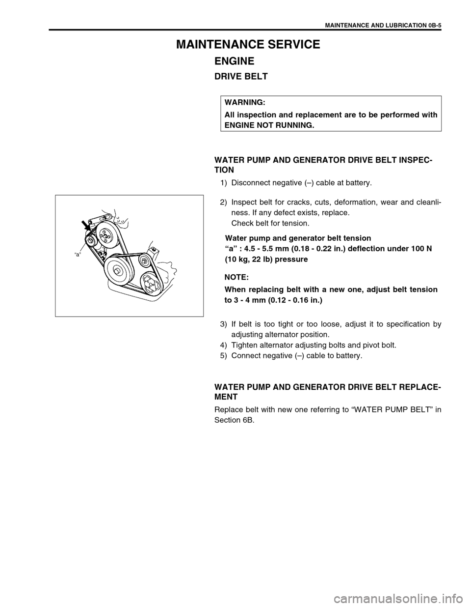
WATER PUMP AND GENERATOR DRIVE BELT INSPEC-
TION
1) Disconnect negative (–) cable at battery.
2) Inspect belt for cracks, cuts, deformation, wear and cleanli-
ness. If any defect exists, replace.
Check belt for tension.
Water pump and generator belt tension
“a” : 4.5 - 5.5 mm (0.18 - 0.22 in.) deflection under 100 N
(10 kg, 22 lb) pressure
3) If belt is too tight or too loose, adjust it to specification by
adjusting alternator position.
4) Tighten alternator adjusting bolts and pivot bolt.
5) Connect negative (–) cable to battery.
WATER PUMP AND GENERATOR DRIVE BELT REPLACE-
MENT
Replace belt with new one referring to “WATER PUMP BELT” in
Section 6B.WARNING:
All inspection and replacement are to be performed with
ENGINE NOT RUNNING.
NOTE:
When replacing belt with a new one, adjust belt tension
to 3 - 4 mm (0.12 - 0.16 in.)
Page 35 of 698
0B-6 MAINTENANCE AND LUBRICATION
A/C COMPRESSOR DRIVE BELT (IF EQUIPPED) INSPEC-
TION
1) Disconnect negative (–) cable at battery.
2) Inspect belt for cracks, cuts, deformation, wear and cleanli-
ness. If any defect exists, replace.
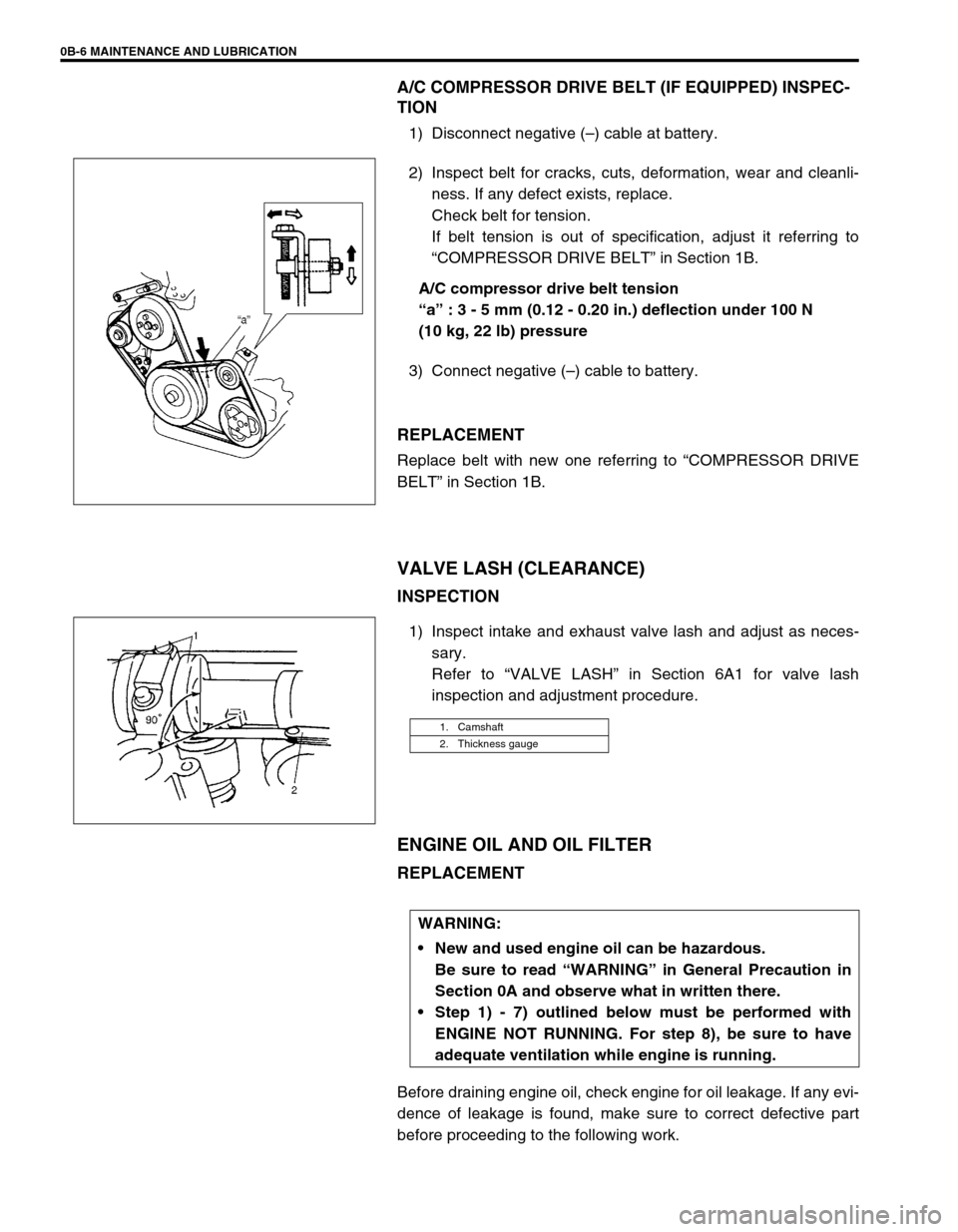
Check belt for tension.
If belt tension is out of specification, adjust it referring to
“COMPRESSOR DRIVE BELT” in Section 1B.
A/C compressor drive belt tension
“a” : 3 - 5 mm (0.12 - 0.20 in.) deflection under 100 N
(10 kg, 22 lb) pressure
3) Connect negative (–) cable to battery.
REPLACEMENT
Replace belt with new one referring to “COMPRESSOR DRIVE
BELT” in Section 1B.
VALVE LASH (CLEARANCE)
INSPECTION
1) Inspect intake and exhaust valve lash and adjust as neces-
sary.
Refer to “VALVE LASH” in Section 6A1 for valve lash
inspection and adjustment procedure.
ENGINE OIL AND OIL FILTER
REPLACEMENT
Before draining engine oil, check engine for oil leakage. If any evi-
dence of leakage is found, make sure to correct defective part
before proceeding to the following work.
1. Camshaft
2. Thickness gauge
WARNING:
New and used engine oil can be hazardous.
Be sure to read “WARNING” in General Precaution in
Section 0A and observe what in written there.
Step 1) - 7) outlined below must be performed with
ENGINE NOT RUNNING. For step 8), be sure to have
adequate ventilation while engine is running.
Page 37 of 698
0B-8 MAINTENANCE AND LUBRICATION
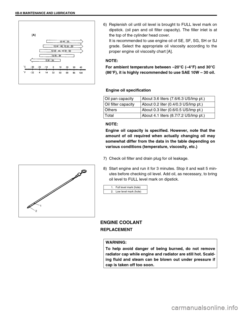
6) Replenish oil until oil level is brought to FULL level mark on
dipstick. (oil pan and oil filter capacity). The filler inlet is at
the top of the cylinder head cover.
It is recommended to use engine oil of SE, SF, SG, SH or SJ
grade. Select the appropriate oil viscosity according to the
proper engine oil viscosity chart [A].
Engine oil specification
7) Check oil filter and drain plug for oil leakage.
8) Start engine and run it for 3 minutes. Stop it and wait 5 min-
utes before checking oil level. Add oil, as necessary, to bring
oil level to FULL level mark on dipstick.
ENGINE COOLANT
REPLACEMENT
NOTE:
For ambient temperature between –20°C (–4°F) and 30°C
(86°F), it is highly recommended to use SAE 10W – 30 oil.
Oil pan capacity About 3.6 liters (7.6/6.3 US/lmp pt.)
Oil filter capacity About 0.2 liter (0.4/0.3 US/lmp pt.)
Others About 0.3 liter (0.6/0.5 US/lmp pt.)
Total About 4.1 liters (8.7/7.2 US/lmp pt.)
NOTE:
Engine oil capacity is specified. However, note that the
amount of oil required when actually changing oil may
somewhat differ from the data in the table depending on
various conditions (temperature, viscosity, etc.)
1. Full level mark (hole)
2. Low level mark (hole)
WARNING:
To help avoid danger of being burned, do not remove
radiator cap while engine and radiator are still hot. Scald-
ing fluid and steam can be blown out under pressure if
cap is taken off too soon.
Page 45 of 698
0B-16 MAINTENANCE AND LUBRICATION
3) Check steering linkage for looseness and damage. Repair or
replace defective parts, if any.
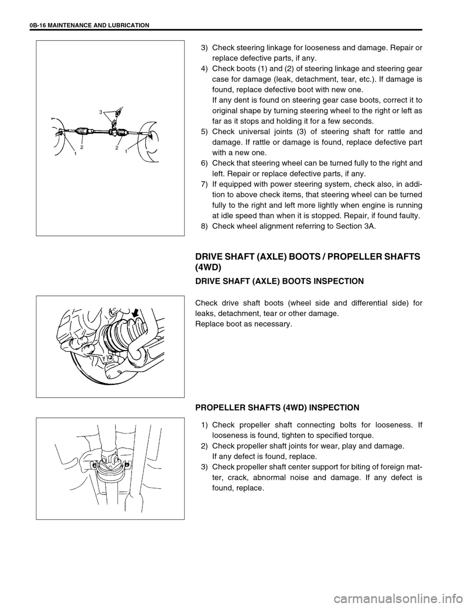
4) Check boots (1) and (2) of steering linkage and steering gear
case for damage (leak, detachment, tear, etc.). If damage is
found, replace defective boot with new one.
If any dent is found on steering gear case boots, correct it to
original shape by turning steering wheel to the right or left as
far as it stops and holding it for a few seconds.
5) Check universal joints (3) of steering shaft for rattle and
damage. If rattle or damage is found, replace defective part
with a new one.
6) Check that steering wheel can be turned fully to the right and
left. Repair or replace defective parts, if any.
7) If equipped with power steering system, check also, in addi-
tion to above check items, that steering wheel can be turned
fully to the right and left more lightly when engine is running
at idle speed than when it is stopped. Repair, if found faulty.
8) Check wheel alignment referring to Section 3A.
DRIVE SHAFT (AXLE) BOOTS / PROPELLER SHAFTS
(4WD)
DRIVE SHAFT (AXLE) BOOTS INSPECTION
Check drive shaft boots (wheel side and differential side) for
leaks, detachment, tear or other damage.
Replace boot as necessary.
PROPELLER SHAFTS (4WD) INSPECTION
1) Check propeller shaft connecting bolts for looseness. If
looseness is found, tighten to specified torque.
2) Check propeller shaft joints for wear, play and damage.
If any defect is found, replace.
3) Check propeller shaft center support for biting of foreign mat-
ter, crack, abnormal noise and damage. If any defect is
found, replace.
Page 48 of 698
MAINTENANCE AND LUBRICATION 0B-19
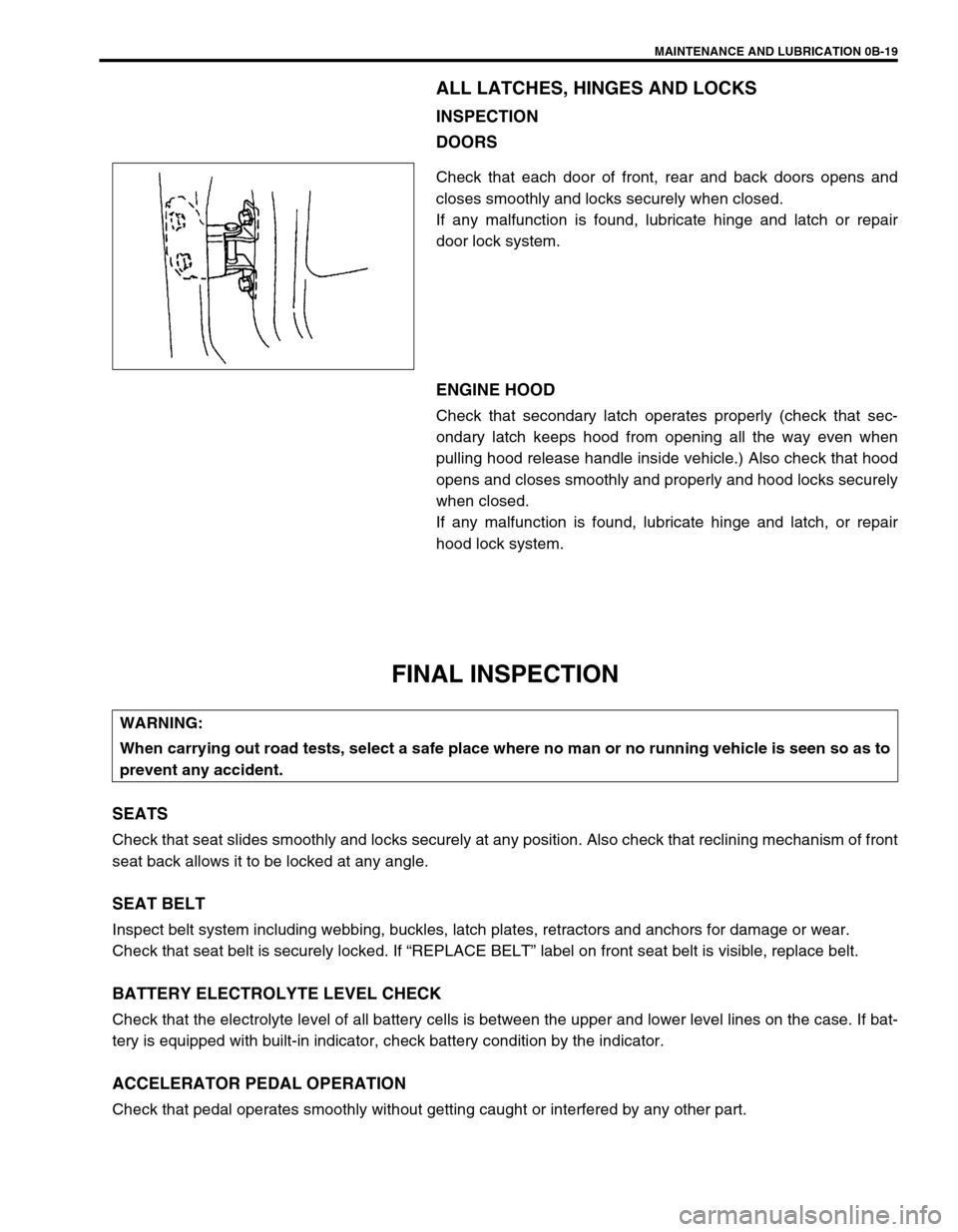
ALL LATCHES, HINGES AND LOCKS
INSPECTION
DOORS
Check that each door of front, rear and back doors opens and
closes smoothly and locks securely when closed.
If any malfunction is found, lubricate hinge and latch or repair
door lock system.
ENGINE HOOD
Check that secondary latch operates properly (check that sec-
ondary latch keeps hood from opening all the way even when
pulling hood release handle inside vehicle.) Also check that hood
opens and closes smoothly and properly and hood locks securely
when closed.
If any malfunction is found, lubricate hinge and latch, or repair
hood lock system.
FINAL INSPECTION
SEATS
Check that seat slides smoothly and locks securely at any position. Also check that reclining mechanism of front
seat back allows it to be locked at any angle.
SEAT BELT
Inspect belt system including webbing, buckles, latch plates, retractors and anchors for damage or wear.
Check that seat belt is securely locked. If “REPLACE BELT” label on front seat belt is visible, replace belt.
BATTERY ELECTROLYTE LEVEL CHECK
Check that the electrolyte level of all battery cells is between the upper and lower level lines on the case. If bat-
tery is equipped with built-in indicator, check battery condition by the indicator.
ACCELERATOR PEDAL OPERATION
Check that pedal operates smoothly without getting caught or interfered by any other part.
WARNING:
When carrying out road tests, select a safe place where no man or no running vehicle is seen so as to
prevent any accident.