Page 170 of 698
ELECTRICAL POWER STEERING (P/S) SYSTEM 3B1-29
ON-VEHICLE SERVICE
P/S CONTROL MODULE
REMOVAL
1) Disconnect negative cable at battery.
2) Remove steering column hole cover.
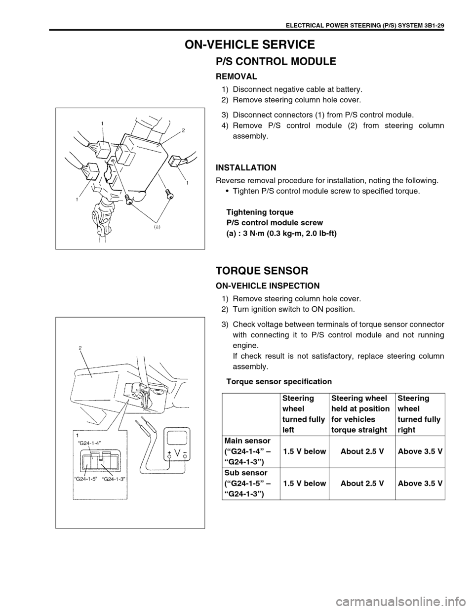
3) Disconnect connectors (1) from P/S control module.
4) Remove P/S control module (2) from steering column
assembly.
INSTALLATION
Reverse removal procedure for installation, noting the following.
Tighten P/S control module screw to specified torque.
Tightening torque
P/S control module screw
(a) : 3 N·m (0.3 kg-m, 2.0 lb-ft)
TORQUE SENSOR
ON-VEHICLE INSPECTION
1) Remove steering column hole cover.
2) Turn ignition switch to ON position.
3) Check voltage between terminals of torque sensor connector
with connecting it to P/S control module and not running
engine.
If check result is not satisfactory, replace steering column
assembly.
Torque sensor specification
Steering
wheel
turned fully
leftSteering wheel
held at position
for vehicles
torque straightSteering
wheel
turned fully
right
Main sensor
(“G24-1-4” –
“G24-1-3”)1.5 V below About 2.5 V Above 3.5 V
Sub sensor
(“G24-1-5” –
“G24-1-3”)1.5 V below About 2.5 V Above 3.5 V
Page 271 of 698
4B-2 PROPELLER SHAFTS
PROPELLER SHAFT JOINT CHECK
If universal joints are suspected of producing chattering or rattling
noise, inspect them for wear. Check to see if cross spider rattles
in yokes or if splines are worn down and replace defective propel-
ler shaft with new one.
Noise coming from universal joint can be easily distinguished
from other noises because rhythm of chattering or rattling is in
step with cruising speed. Noise is pronounced particularly on
standing start or in coasting condition (when braking effect of
engine is showing in the drive line).
ON-VEHICLE SERVICE
REMOVAL
1) Hoist vehicle.
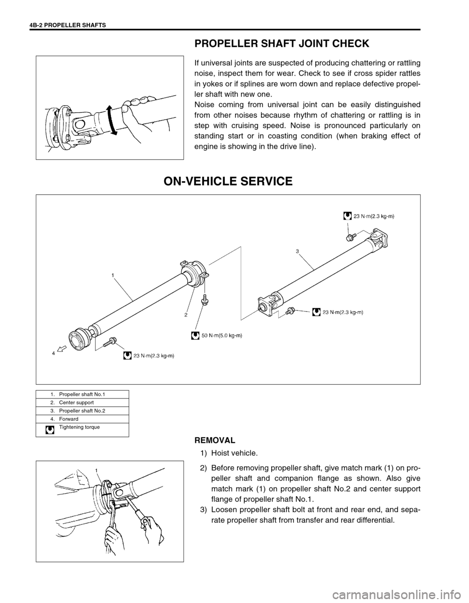
2) Before removing propeller shaft, give match mark (1) on pro-
peller shaft and companion flange as shown. Also give
match mark (1) on propeller shaft No.2 and center support
flange of propeller shaft No.1.
3) Loosen propeller shaft bolt at front and rear end, and sepa-
rate propeller shaft from transfer and rear differential.
1. Propeller shaft No.1
2. Center support
3. Propeller shaft No.2
4. Forward
Tightening torque
Page 280 of 698
BRAKES 5-7
Brake warning lamp
lights after engine
startParking brake applied Release parking brake and check
that brake warning lamp turns off.
Insufficient amount of brake fluid Add brake fluid.
Brake fluid leaking from brake line Investigate leaky point, correct it
and add brake fluid.
Brake warning lamp circuit faulty Repair circuit.
Malfunctioning EBD system, if equipped with
ABS.Check system referring to Table-E
of Section 5E1.
Brake warning lamp
turns on when brake
is appliedBrake fluid leaking from brake line Investigate leaky point, correct it
and add brake fluid.
Insufficient amount of brake fluid Add brake fluid.
Brake warning lamp
fails to turn on even
when parking brake is
appliedBrake warning lamp circuit faulty Replace bulb or repair circuit.
ABS warning lamp
turns on after engine
start (If equipped)Malfunctioning ABS Check system referring to DIAG-
NOSIS of Section 5E1.
ABS warning lamp
turns on when brake
is applied (If
equipped)Malfunctioning ABS Check system referring to DIAG-
NOSIS of Section 5E1.
ABS warning lamp
does not turn on for 2
sec. after ignition
switch has turned ONBulb burnt out Replace bulb.
Malfunctioning ABS Check system referring to DIAG-
NOSIS of Section 5E1.
ABS warning lamp
flashesNew ABS hydraulic unit/control module assem-
bly installed.Perform “ABS Hydraulic Unit Oper-
ation Check”. Condition Possible Cause Correction
Page 282 of 698
BRAKES 5-9
EXCESSIVE PEDAL TRAVEL INSPECTION
1) Start engine.
2) Depress brake pedal a few times.
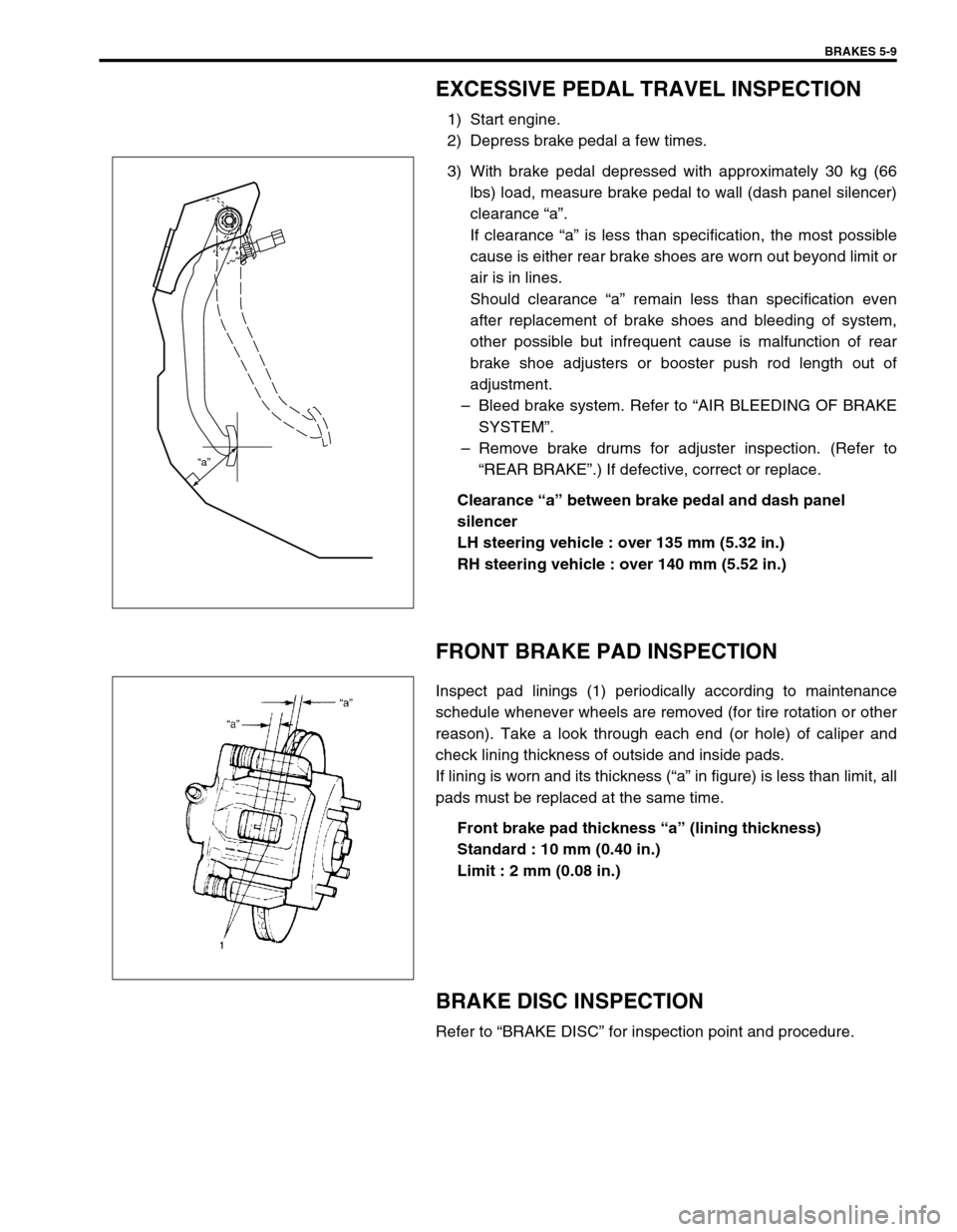
3) With brake pedal depressed with approximately 30 kg (66
lbs) load, measure brake pedal to wall (dash panel silencer)
clearance “a”.
If clearance “a” is less than specification, the most possible
cause is either rear brake shoes are worn out beyond limit or
air is in lines.
Should clearance “a” remain less than specification even
after replacement of brake shoes and bleeding of system,
other possible but infrequent cause is malfunction of rear
brake shoe adjusters or booster push rod length out of
adjustment.
–Bleed brake system. Refer to “AIR BLEEDING OF BRAKE
SYSTEM”.
–Remove brake drums for adjuster inspection. (Refer to
“REAR BRAKE”.) If defective, correct or replace.
Clearance “a” between brake pedal and dash panel
silencer
LH steering vehicle : over 135 mm (5.32 in.)
RH steering vehicle : over 140 mm (5.52 in.)
FRONT BRAKE PAD INSPECTION
Inspect pad linings (1) periodically according to maintenance
schedule whenever wheels are removed (for tire rotation or other
reason). Take a look through each end (or hole) of caliper and
check lining thickness of outside and inside pads.
If lining is worn and its thickness (“a” in figure) is less than limit, all
pads must be replaced at the same time.
Front brake pad thickness “a” (lining thickness)
Standard : 10 mm (0.40 in.)
Limit : 2 mm (0.08 in.)
BRAKE DISC INSPECTION
Refer to “BRAKE DISC” for inspection point and procedure.
“a”
Page 284 of 698
BRAKES 5-11
Parking brake stroke (When lever is pulled up at 200 N (20
kg, 44 lbs)
: 4 to 9 notches
BOOSTER OPERATION INSPECTION
There are two ways to perform this inspection, with and without a
tester. Ordinarily, it is possible to roughly determine its condition
without using a tester.
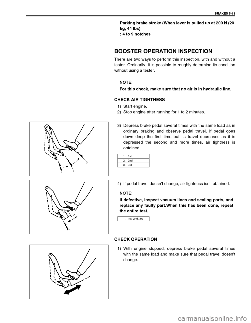
CHECK AIR TIGHTNESS
1) Start engine.
2) Stop engine after running for 1 to 2 minutes.
3) Depress brake pedal several times with the same load as in
ordinary braking and observe pedal travel. If pedal goes
down deep the first time but its travel decreases as it is
depressed the second and more times, air tightness is
obtained.
4) If pedal travel doesn’t change, air tightness isn’t obtained.
CHECK OPERATION
1) With engine stopped, depress brake pedal several times
with the same load and make sure that pedal travel doesn’t
change. NOTE:
For this check, make sure that no air is in hydraulic line.
1. 1st
2. 2nd
3. 3rd
NOTE:
If defective, inspect vacuum lines and sealing parts, and
replace any faulty part.When this has been done, repeat
the entire test.
1. 1st, 2nd, 3rd
Page 285 of 698
5-12 BRAKES
2) Start engine while depressing brake pedal. If pedal travel
increases a little, operation is satisfactory. But no change in
pedal travel indicates malfunction.
CHECK AIR TIGHTNESS UNDER LOAD
1) With engine running, depress brake pedal. Then stop engine
while holding brake pedal depressed.
2) Hold brake pedal depressed for 30 seconds. If pedal height
does not change, condition is good. But it isn’t if pedal rises.
FLUID PRESSURE TEST (IF EQUIPPED WITH
LSPV)
Test procedure for LSPV assembly is as follows.
Before testing, confirm the following.
Fuel tank is filled with fuel fully.
Vehicle is equipped with spare tire, tools, jack and jack han-
dle.
H: Hold
H: Hold
T: 30 seconds
Page 342 of 698
ANTILOCK BRAKE SYSTEM (ABS) 5E-17
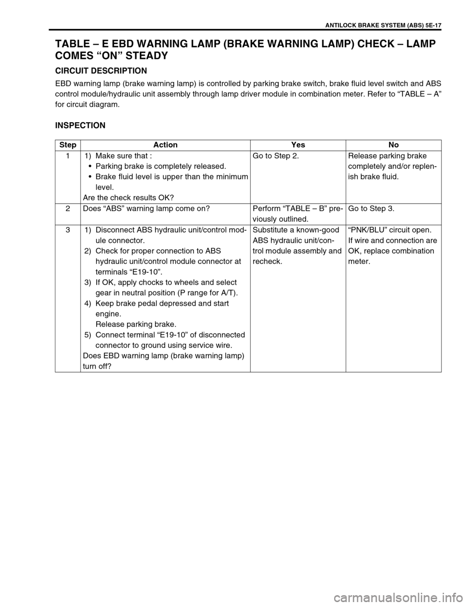
TABLE – E EBD WARNING LAMP (BRAKE WARNING LAMP) CHECK – LAMP
COMES “ON” STEADY
CIRCUIT DESCRIPTION
EBD warning lamp (brake warning lamp) is controlled by parking brake switch, brake fluid level switch and ABS
control module/hydraulic unit assembly through lamp driver module in combination meter. Refer to “TABLE – A”
for circuit diagram.
INSPECTION
Step Action Yes No
1 1) Make sure that :
Parking brake is completely released.
Brake fluid level is upper than the minimum
level.
Are the check results OK?Go to Step 2. Release parking brake
completely and/or replen-
ish brake fluid.
2Does “ABS” warning lamp come on? Perform “TABLE – B” pre-
viously outlined.Go to Step 3.
3 1) Disconnect ABS hydraulic unit/control mod-
ule connector.
2) Check for proper connection to ABS
hydraulic unit/control module connector at
terminals “E19-10”.
3) If OK, apply chocks to wheels and select
gear in neutral position (P range for A/T).
4) Keep brake pedal depressed and start
engine.
Release parking brake.
5) Connect terminal “E19-10” of disconnected
connector to ground using service wire.
Does EBD warning lamp (brake warning lamp)
turn off?Substitute a known-good
ABS hydraulic unit/con-
trol module assembly and
recheck.“PNK/BLU” circuit open.
If wire and connection are
OK, replace combination
meter.
Page 352 of 698
ANTILOCK BRAKE SYSTEM (ABS) 5E-27
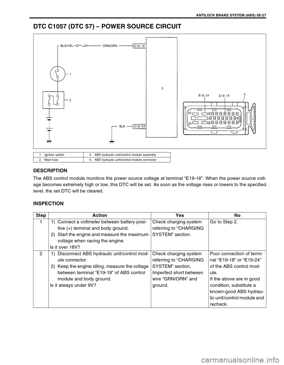
DTC C1057 (DTC 57) – POWER SOURCE CIRCUIT
DESCRIPTION
The ABS control module monitors the power source voltage at terminal “E19-18”. When the power source volt-
age becomes extremely high or low, this DTC will be set. As soon as the voltage rises or lowers to the specified
level, the set DTC will be cleared.
INSPECTION
1. Ignition switch 3. ABS hydraulic unit/control module assembly
2. Main fuse 4. ABS hydraulic unit/control module connector
Step Action Yes No
1 1) Connect a voltmeter between battery posi-
tive (+) terminal and body ground.
2) Start the engine and measure the maximum
voltage when racing the engine.
Is it over 18V?Check charging system
referring to “CHARGING
SYSTEM” section.Go to Step 2.
2 1) Disconnect ABS hydraulic unit/control mod-
ule connector.
2) Keep the engine idling, measure the voltage
between terminal “E19-18” of ABS control
module and body ground.
Is it always under 9V?Check charging system
referring to “CHARGING
SYSTEM” section.
Imperfect short between
wire “GRN/ORN” and
ground.Poor connection of termi-
nal “E19-18” or “E19-24”
of the ABS control mod-
ule.
If the above are in good
condition, substitute a
known-good ABS hydrau-
lic unit/control module and
recheck.