2000 SUZUKI SWIFT check engine
[x] Cancel search: check enginePage 49 of 698

0B-20 MAINTENANCE AND LUBRICATION
ENGINE START
Check engine start for readiness.
On automatic transmission vehicles, try to start the engine in each select lever position. The starting motor
should crank only in “P” (Park) or “N” (Neutral).
On manual transmission vehicles, place the shift lever in “Neutral,” depress clutch pedal fully any try to start.
EXHAUST SYSTEM CHECK
Check for leakage, cracks or loose supports.
CLUTCH (FOR MANUAL TRANSMISSION)
Check for the following.
Clutch is completely released when depressing clutch pedal,
No slipping clutch occurs when releasing pedal and accelerating.
Clutch itself is free from any abnormal condition.
GEARSHIFT OR SELECT LEVER (TRANSMISSION)
Check gear shift or select lever for smooth shifting to all positions and for good performance of transmission in
any position.
With automatic transmission equipped vehicle, also check that shift indicator indicates properly according to
which position select lever is shifted to.
With automatic transmission equipped vehicle, make sure that vehicle is at complete stop when shifting select
lever to “P” range position and release all brakes.
BRAKE
Foot Brake
Check the followings:
that brake pedal has proper travel,
that brake works properly,
that it is free from noise,
that vehicle does not pull to one side when brake is applied.
and that brake do not drag.
Parking Brake
Check that lever has proper travel.
Check to ensure that parking brake is fully effective when the vehicle is stopped on the safe slope and brake
lever is pulled all the way.WARNING:
Before performing the following check, be sure to have enough room around the vehicle. Then, firmly
apply both the parking brake and the regular brakes. Do not use the accelerator pedal. If the engine
starts, be ready to turn off the ignition promptly. Take these precautions because the vehicle could
move without warning and possibly cause personal injury or property damage.
WARNING:
With vehicle parked on a fairly steep slope, make sure nothing is in the way downhill to avoid any per-
sonal injury or property damage. Be prepared to apply regular brake quickly even if vehicle should
start to move.
Page 50 of 698

MAINTENANCE AND LUBRICATION 0B-21
STEERING
Check to ensure that steering wheel is free from instability, or abnormally heavy feeling.
Check that the vehicle does not wander or pull to one side.
ENGINE
Check that engine responds readily at all speeds.
Check that engine is free from abnormal noise and abnormal vibration.
BODY, WHEELS AND POWER TRANSMITTING SYSTEM
Check that body, wheels and power transmitting system are free from abnormal noise and abnormal vibration or
any other abnormal condition.
METERS AND GAUGE
Check that speedometer, odometer, fuel meter, temperature gauge, etc. are operating accurately.
LIGHTS
Check that all lights operate properly.
WINDSHIELD DEFROSTER
Periodically check that air comes out from defroster outlet when operating heater or air conditioning.
Set mode control lever to defroster position and fan switch lever to “HI” position for this check.
RECOMMENDED FLUIDS AND LUBRICANTS
Engine oil SE, SF, SG, SH or SJ grade (Refer to “ENGINE OIL AND OIL FILTER”
in this section for engine oil viscosity.)
Engine coolant
(Ethylene glycol base coolant)“Antifreeze/Anticorrosion coolant”
Brake fluid DOT 3
Manual transmission oil Refer to “M/T OIL CHANGE” in Section 7A.
Transfer oil (4WD) Refer to “TRANSFER OIL CHANGE” in Section 7D.
Differential oil (4WD) Refer to “DIFFERENTIAL OIL CHANGE” in Section 7F.
Automatic transmission fluid
An equivalent of DEXRON
®-III
Door hinges Engine oil or water resistance chassis grease
Hood latch assembly Engine oil or water resistance chassis grease
Key lock cylinder Spray lubricant
Page 74 of 698

AIR CONDITIONING (OPTIONAL) 1B-9
QUICKLY CHECKING OF REFRIGERANT
CHARGE
The following procedure can be used for quickly checking
whether the A/C system has a proper charge of refrigerant or not.
Run engine at fast idle, and operate A/C at its maximum cooling
capacity for a few minutes.
Then, look at the sight glass (1) on condenser outlet pipe (2) and
compare what is observed with the symptoms listed in below.
CHECKING REFRIGERANT CHARGE
[A] : LH model 3. Bubbles
[B] : RH model 4. A/C refrigerant pressure switch
Item
No.Symptom Charge of refrigerant condi-
tionCorrection
1 Bubbles observed in sight glass Insufficient charge of refrigerant
in systemCheck system for leaks with a
leak tester.
2 No bubbles observed in sight glass No or insufficient charge of
refrigerant in systemRefer to the items 3 and 4.
3 No temperature difference between
compressor inlet and outletEmpty or nearly empty system Evacuate and charge system
and then check it for leaks with
a leak tester.
4 Noticeable temperature difference
between compressor inlet and out-
letProper or too much charge of
refrigerant in systemRefer to the items 5 and 6.
5 When A/C is turned OFF, refriger-
ant in sight glass clears immedi-
ately and remains clearToo much charge of refrigerant
in systemRecharge with specified amount
of refrigerant.
6 When A/C is turned OFF, refriger-
ant in sight glass once produces
bubbles and then clearsProper charge of refrigerant in
systemNo correction needed because
charge of refrigerant is normal.
NOTE:
For specified amount of refrigerant, refer to “OPERATION PROCEDURE FOR A/C WITH REFRIGER-
ANT” in this section.
Page 75 of 698

1B-10 AIR CONDITIONING (OPTIONAL)
PERFORMANCE DIAGNOSIS
1) Confirm that vehicle and environmental conditions are as fol-
lows.
Vehicle is not exposed to direct sun.
Ambient temperature is within 15 – 35°C (59 – 95°F).
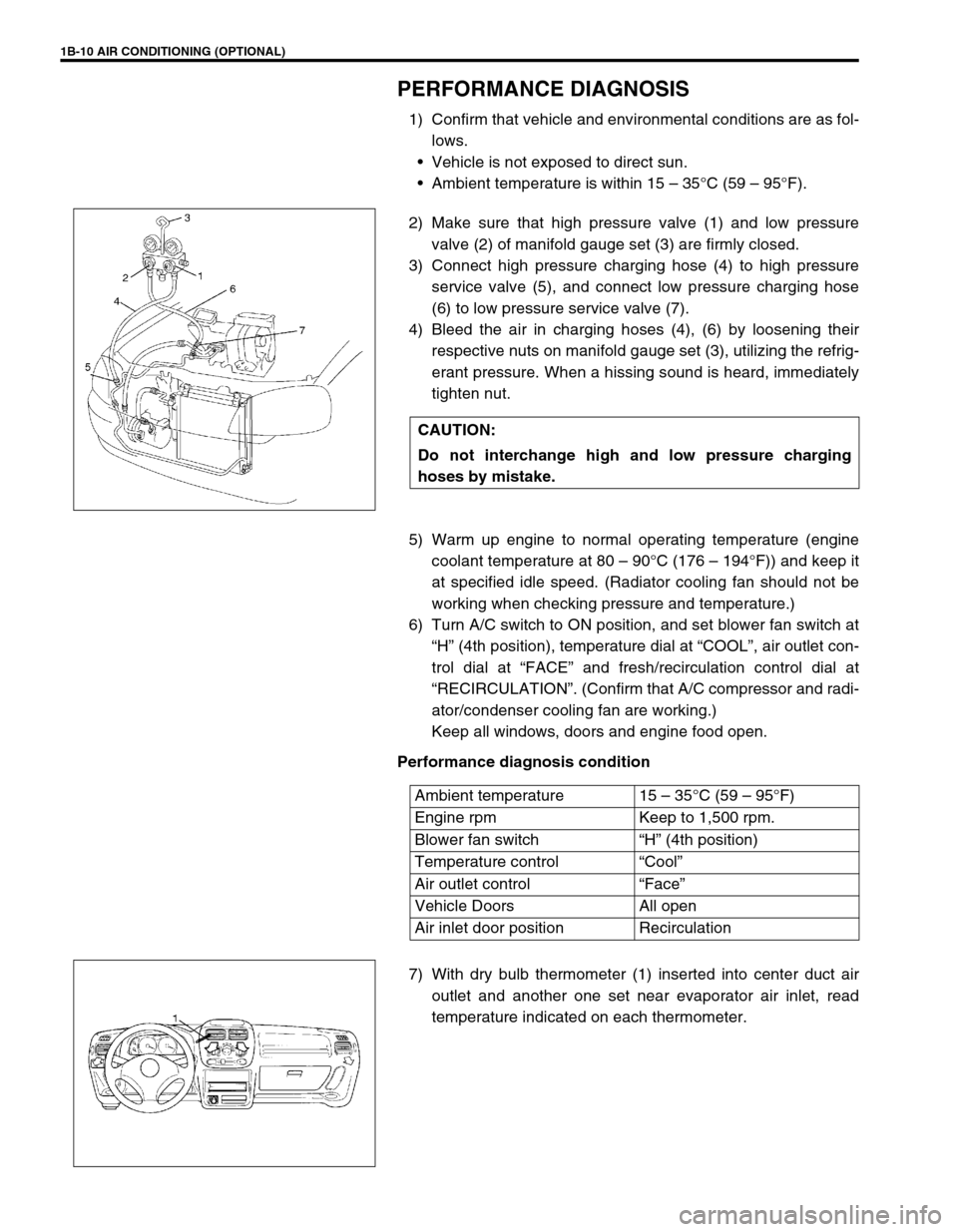
2) Make sure that high pressure valve (1) and low pressure
valve (2) of manifold gauge set (3) are firmly closed.
3) Connect high pressure charging hose (4) to high pressure
service valve (5), and connect low pressure charging hose
(6) to low pressure service valve (7).
4) Bleed the air in charging hoses (4), (6) by loosening their
respective nuts on manifold gauge set (3), utilizing the refrig-
erant pressure. When a hissing sound is heard, immediately
tighten nut.
5) Warm up engine to normal operating temperature (engine
coolant temperature at 80 – 90°C (176 – 194°F)) and keep it
at specified idle speed. (Radiator cooling fan should not be
working when checking pressure and temperature.)
6) Turn A/C switch to ON position, and set blower fan switch at
“H” (4th position), temperature dial at “COOL”, air outlet con-
trol dial at “FACE” and fresh/recirculation control dial at
“RECIRCULATION”. (Confirm that A/C compressor and radi-
ator/condenser cooling fan are working.)
Keep all windows, doors and engine food open.
Performance diagnosis condition
7) With dry bulb thermometer (1) inserted into center duct air
outlet and another one set near evaporator air inlet, read
temperature indicated on each thermometer. CAUTION:
Do not interchange high and low pressure charging
hoses by mistake.
Ambient temperature 15 – 35°C (59 – 95°F)
Engine rpm Keep to 1,500 rpm.
Blower fan switch“H” (4th position)
Temperature control“Cool”
Air outlet control“Face”
Vehicle Doors All open
Air inlet door position Recirculation
Page 77 of 698

1B-12 AIR CONDITIONING (OPTIONAL)
PERFORMANCE DIAGNOSIS TABLE
HIGH PRESSURE GAUGE
LOW PRESSURE GAUGE
THERMOMETER AT CENTER DUCT
NOTE:
If ambient temperature is approximately 30°C (86°F), it is possible to diagnose A/C system in detail
referring to “DETAIL DIAGNOSIS TABLE (AMBIENT TEMPERATURE AT 30 °C (86°F))” under “PER-
FORMANCE DIAGNOSIS” in this section.
Condition Possible Cause Correction
Pressure high
(“A” area of high side
graph)Refrigerant overcharged Recharge.
Expansion valve frozen or clogged Check expansion valve.
Clogged refrigerant passage of high side Clean or replace.
Radiator/condenser cooling fan malfunction (Insufficient
cooling of condenser)Check radiator/condenser cooling fan.
Dirty or bent condenser fins (Insufficient cooling of con-
denser)Clean or repair.
Compressor malfunction (Insufficient oil etc.) Check compressor.
Engine overheat Check engine cooling system referring to
Section 6B.
Pressure low
(“B” area of high side
graph)Insufficient refrigerant (Insufficient charge or leakage) Check for leakage, repair if necessary
and recharge.
Expansion valve malfunction (valve opens too wide) Check expansion valve.
Compressor malfunction (Insufficient compression) Check compressor.
Condition Possible Cause Correction
Pressure high
(“C” area of low side
graph)Expansion valve malfunction (valve opens too wide) Check expansion valve.
Compressor malfunction (Insufficient compression) Check compressor.
Pressure low
(“D” area of low side
graph)Insufficient refrigerant (Insufficient charge or leakage) Check for leakage, repair if necessary
and recharge.
Expansion valve malfunction (valve opens too narrow) Check expansion valve.
Clogged refrigerant passage (crashed pipe) Repair or replace.
Condition Possible Cause Correction
Outlet air temperature at
center duct is high
(Crossing point is in area
“E”)Insufficient or excessive charge of refrigerant Check refrigerant pressure.
Dirty or bent A/C evaporator fins Clean or repair.
Air leakage from cooling (heater) unit or air duct Repair or replace.
Malfunctioning, switch over function of door in cooling
(heater) unitRepair or replace.
Compressor malfunction Check compressor.
Outlet air temperature at
center duct is low
(Crossing point is in area
“F”)Insufficient air volume from center duct (Heater blower
malfunction)Check blower motor and fan.
Compressor malfunction Check compressor.
Page 89 of 698

1B-24 AIR CONDITIONING (OPTIONAL)
CHARGING
CHARGING PROCEDURE
The initial charging of the A/C system is performed from the high
pressure side with the engine stopped.
And next, this method must be followed by charging from the low
pressure side with the engine running.
1) Check to make sure that hoses are routed properly after
evacuating the system.
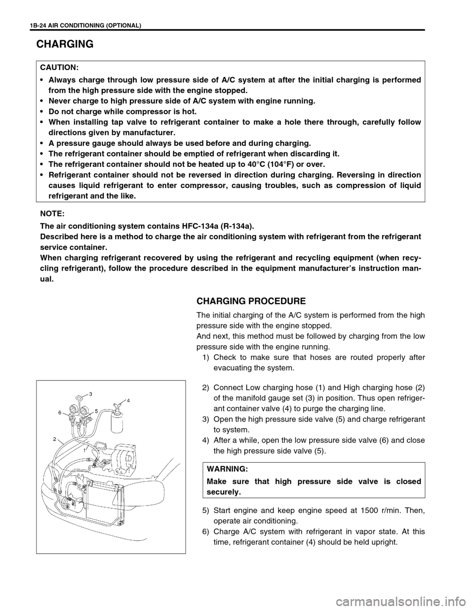
2) Connect Low charging hose (1) and High charging hose (2)
of the manifold gauge set (3) in position. Thus open refriger-
ant container valve (4) to purge the charging line.
3) Open the high pressure side valve (5) and charge refrigerant
to system.
4) After a while, open the low pressure side valve (6) and close
the high pressure side valve (5).
5) Start engine and keep engine speed at 1500 r/min. Then,
operate air conditioning.
6) Charge A/C system with refrigerant in vapor state. At this
time, refrigerant container (4) should be held upright. CAUTION:
Always charge through low pressure side of A/C system at after the initial charging is performed
from the high pressure side with the engine stopped.
Never charge to high pressure side of A/C system with engine running.
Do not charge while compressor is hot.
When installing tap valve to refrigerant container to make a hole there through, carefully follow
directions given by manufacturer.
A pressure gauge should always be used before and during charging.
The refrigerant container should be emptied of refrigerant when discarding it.
The refrigerant container should not be heated up to 40°C (104°F) or over.
Refrigerant container should not be reversed in direction during charging. Reversing in direction
causes liquid refrigerant to enter compressor, causing troubles, such as compression of liquid
refrigerant and the like.
NOTE:
The air conditioning system contains HFC-134a (R-134a).
Described here is a method to charge the air conditioning system with refrigerant from the refrigerant
service container.
When charging refrigerant recovered by using the refrigerant and recycling equipment (when recy-
cling refrigerant), follow the procedure described in the equipment manufacturer’s instruction man-
ual.
WARNING:
Make sure that high pressure side valve is closed
securely.
Page 101 of 698

1B-36 AIR CONDITIONING (OPTIONAL)
A/C SWITCH
REMOVAL AND INSTALLATION
Refer to “HEATER CONTROL ASSEMBLY” in Section 1A.
INSPECTION
Press A/C switch button and check if there is continuity
between terminals “A” and “B”.
Connect battery voltage (+) to terminal “C” and (–) to termi-
nal “A”, and then press A/C Switch button and check if indi-
cator lamp lights.
RADIATOR/CONDENSER COOLING FAN
MOTOR RELAY No.1, No.2 and No.3
INSPECTION
Refer to “RADIATOR FAN RELAY” in Section 6B.
COMPRESSOR
REMOVAL
1) Run engine at idle speed with air conditioning ON for 10 min-
utes. After that stop the engine.
2) Disconnect negative (–) cable at battery.
3) Recover refrigerant from refrigeration system by referring to
“RECOVERY” in this section.
4) Remove front bumper by referring to “FRONT BUMPER” in
Section 8.
5) Remove engine food cover (1) from vehicle body.
NOTE:
The amount of removed compressor oil must be mea-
sured for replenishing compressor oil.
Page 142 of 698

ELECTRICAL POWER STEERING (P/S) SYSTEM 3B1-1
6F1
6F2
6G
6H
6K
7A
7A1
3B1
7D
7E
7F
8A
8B
8C
8D
8E
9
10
10A
10B
SECTION 3B1
ELECTRICAL POWER STEERING (P/S) SYSTEM
CONTENTS
GENERAL DESCRIPTION .............................3B1-2
SYSTEM COMPONENTS ........................... 3B1-2
WIRING DIAGRAM ..................................... 3B1-3
DIAGNOSIS ....................................................3B1-4
ON-BOARD DIAGNOSTIC SYSTEM .......... 3B1-4
PRECAUTIONS IN DIAGNOSING
TROUBLES ................................................. 3B1-4
SYSTEM CHECK FLOW TABLE ................ 3B1-5
MALFUNCTION INDICATOR LAMP
(“EPS” WARNING LAMP) CHECK.............. 3B1-7
DTC CHECK ............................................... 3B1-8
DTC CLEARANCE ...................................... 3B1-9
SERIAL DATA LINK CIRCUIT CHECK ..... 3B1-10
DTC TABLE .............................................. 3B1-11
TABLE A - MALFUNCTION INDICATOR
LAMP DOES NOT COME ON AT
IGNITION SWITCH ON BUT LEAVING
ENGINE OFF ............................................ 3B1-13
TABLE B - MALFUNCTION INDICATOR
LAMP FLASHES AT IGNITION SWITCH
ON ............................................................. 3B1-15
TABLE C - MALFUNCTION INDICATOR
LAMP DOES NOT FLASH, JUST
REMAINS ON OR JUST REMAINS OFF
EVEN WITH DIAGNOSIS SWITCH
TERMINAL GROUNDED .......................... 3B1-15
DTC C1111 (DTC No.11) TORQUE
SENSOR MAIN CIRCUIT FAILURE ......... 3B1-16
DTC C1113 (DTC No.13) TORQUE
SENSOR MAIN AND SUB CIRCUIT
FAILURE ................................................... 3B1-16DTC C1115 (DTC No.15) TORQUE
SENSOR SUB CIRCUIT FAILURE........... 3B1-16
DTC C1114 (DTC No.14) TORQUE
SENSOR 5V POWER SUPPLY CIRCUIT
FAILURE ................................................... 3B1-17
DTC C1116 (DTC No.16) TORQUE
SENSOR 8V POWER SUPPLY CIRCUIT
FAILURE ................................................... 3B1-18
DTC C1121/C1123/C1124
(DTC No.21/23/24) VSS CIRCUIT
FAILURE ................................................... 3B1-19
DTC C1122 (DTC No.22) ENGINE
SPEED SIGNAL CIRCUIT FAILURE ........ 3B1-20
DTC C1141/C1142/C1143/C1144/C1145
(DTC No.41/42/43/44/45) MOTOR
CIRCUIT FAILURE ................................... 3B1-21
DTC C1151 (DTC No.51) CLUTCH
CIRCUIT FAILURE ................................... 3B1-22
DTC C1153(DTC No.53) P/S CONTROL
MODULE POWER SUPPLY CIRCUIT
FAILURE ................................................... 3B1-24
DTC C1152/C1154/C1155
(DTC No.52/54/55) P/S CONTROL
MODULE FAILURE .................................. 3B1-24
TROUBLE DIAGNOSIS (FOR TROUBLE
NOT INDICATED BY ON BOARD
DIAGNOSTIC SYSTEM)........................... 3B1-25
INSPECTION OF P/S CONTROL
MODULE AND ITS CIRCUITS ................. 3B1-26
STEERING WHEEL PLAY
INSPECTION ............................................ 3B1-28 WARNING:
For vehicles equipped with Supplemental Restraint (Air Bag) System :
Service on and around the air bag system components or wiring must be performed only by an
authorized SUZUKI dealer. Refer to “Air Bag System Components and Wiring Location View” under
“General Description” in air bag system section in order to confirm whether you are performing ser-
vice on or near the air bag system components or wiring. Please observe all WARNINGS and “Ser-
vice Precautions” under “On-Vehicle Service” in air bag system section before performing service
on or around the air bag system components or wiring. Failure to follow WARNINGS could result in
unintentional activation of the system or could render the system inoperative. Either of these two
conditions may result in severe injury.
Technical service work must be started at least 90 seconds after the ignition switch is turned to the
“LOCK” position and the negative cable is disconnected from the battery. Otherwise, the system
may be activated by reserve energy in the Sensing and Diagnostic Module (SDM).