2000 SUZUKI SWIFT Ignition system
[x] Cancel search: Ignition systemPage 628 of 698

ENGINE AND EMISSION CONTROL SYSTEM 6E1-7
ELECTRONIC CONTROL SYSTEM
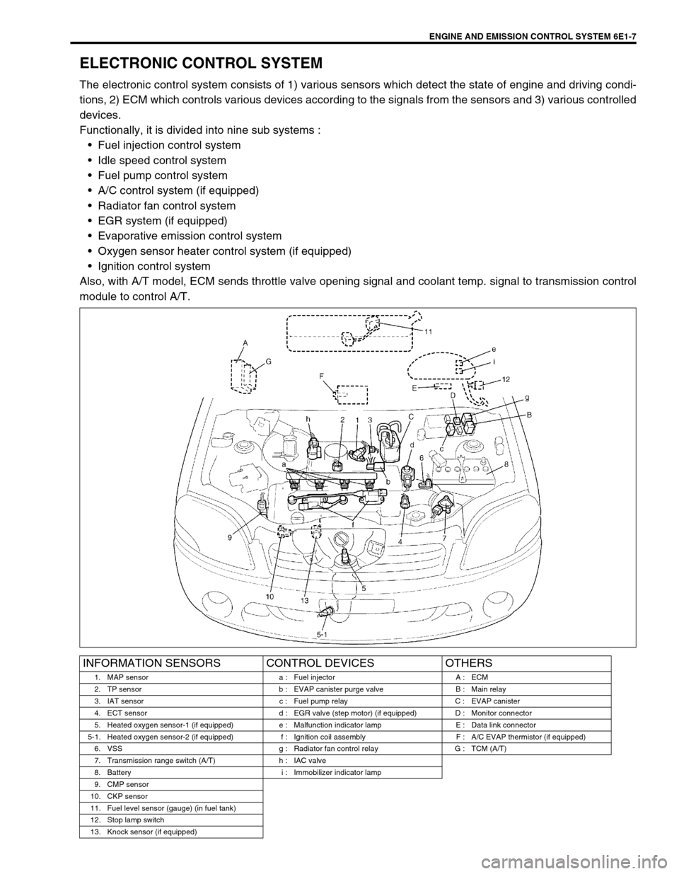
The electronic control system consists of 1) various sensors which detect the state of engine and driving condi-
tions, 2) ECM which controls various devices according to the signals from the sensors and 3) various controlled
devices.
Functionally, it is divided into nine sub systems :
Fuel injection control system
Idle speed control system
Fuel pump control system
A/C control system (if equipped)
Radiator fan control system
EGR system (if equipped)
Evaporative emission control system
Oxygen sensor heater control system (if equipped)
Ignition control system
Also, with A/T model, ECM sends throttle valve opening signal and coolant temp. signal to transmission control
module to control A/T.
INFORMATION SENSORS CONTROL DEVICES OTHERS
1. MAP sensor a : Fuel injector A : ECM
2. TP sensor b : EVAP canister purge valve B : Main relay
3. IAT sensor c : Fuel pump relay C : EVAP canister
4. ECT sensor d : EGR valve (step motor) (if equipped) D : Monitor connector
5. Heated oxygen sensor-1 (if equipped) e : Malfunction indicator lamp E : Data link connector
5-1. Heated oxygen sensor-2 (if equipped) f : Ignition coil assembly F : A/C EVAP thermistor (if equipped)
6. VSS g : Radiator fan control relay G : TCM (A/T)
7. Transmission range switch (A/T) h : IAC valve
8. Battery i : Immobilizer indicator lamp
9. CMP sensor
10. CKP sensor
11. Fuel level sensor (gauge) (in fuel tank)
12. Stop lamp switch
13. Knock sensor (if equipped)
Page 629 of 698

6E1-8 ENGINE AND EMISSION CONTROL SYSTEM
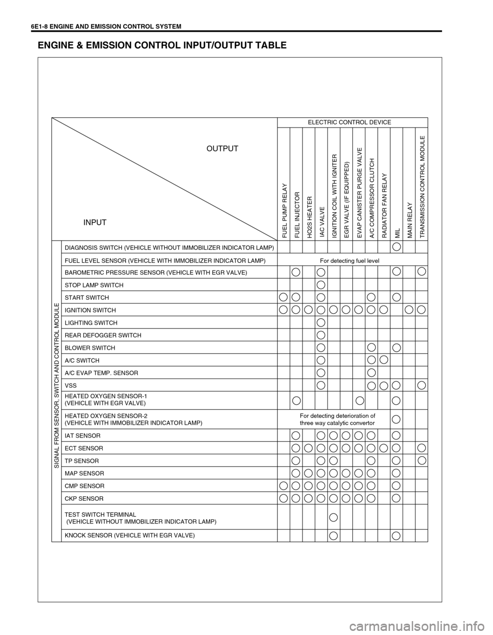
ENGINE & EMISSION CONTROL INPUT/OUTPUT TABLE
INPUTOUTPUT
ELECTRIC CONTROL DEVICE
FUEL LEVEL SENSOR (VEHICLE WITH IMMOBILIZER INDICATOR LAMP) For detecting fuel level DIAGNOSIS SWITCH (VEHICLE WITHOUT IMMOBILIZER INDICATOR LAMP)
BAROMETRIC PRESSURE SENSOR (VEHICLE WITH EGR VALVE)
STOP LAMP SWITCH
START SWITCH
IGNITION SWITCH
LIGHTING SWITCH
REAR DEFOGGER SWITCH
BLOWER SWITCH
A/C SWITCH
A/C EVAP TEMP. SENSOR
VSS
HEATED OXYGEN SENSOR-1
(VEHICLE WITH EGR VALVE)
HEATED OXYGEN SENSOR-2
(VEHICLE WITH IMMOBILIZER INDICATOR LAMP)For detecting deterioration of
three way catalytic convertor
IAT SENSOR
ECT SENSOR
TP SENSOR
MAP SENSOR
CMP SENSOR
CKP SENSOR
TEST SWITCH TERMINAL
(VEHICLE WITHOUT IMMOBILIZER INDICATOR LAMP)
KNOCK SENSOR (VEHICLE WITH EGR VALVE)
FUEL PUMP RELAY
FUEL INJECTOR
HO2S HEATER
IAC VALVE
IGNITION COIL WITH IGNITER
EGR VALVE (IF EQUIPPED)
EVAP CANISTER PURGE VALVE
A/C COMPRESSOR CLUTCH
RADIATOR FAN RELAY
MIL
MAIN RELAY
TRANSMISSION CONTROL MODULE SIGNAL FROM SENSOR, SWITCH AND CONTROL MODULE
Page 631 of 698

6E1-10 ENGINE AND EMISSION CONTROL SYSTEM
1. CKP sensor 20. Blank 39. Ignition coil assembly (for No.1 and No.4 spark plugs)
2. CMP sensor 21. A/C switch 40. Ignition coil assembly (for No.2 and No.3 spark plugs)
3. VSS 22. A/C pressure switch 41. Stop lamp switch
4. MAP sensor 23. Immobilizer control module 42. Stop lamp
5. Knock sensor (if equipped) 24. Data link connector 43. Lighting switch
6. TP sensor 25. Injector No.1 44. Position lamp
7. ECT sensor 26. Injector No.2 45. Rear defogger switch
8. IAT sensor 27. Injector No.3 46. Rear defogger
9. Heated oxygen sensor-1 (if equipped) 28. Injector No.4 47. A/C compressor clutch (if equipped)
10. Heated oxygen sensor-2 (if equipped) 29. IAC valve 48. Ignition switch
11. A/C evaporator temp. sensor 30. EVAP canister purge valve 49. Main relay
12. Combination meter 31. Fuel pump relay 50. Transmission range switch (A/T)
13. Fuel level sensor (vehicle with immobilizer
indicator lamp)32. Fuel pump 51. Starting motor
14. TCM 33. Radiator fan relay 52. Shield wire
15. Transmission range switch 34. Radiator fan motor 53. Main fuse
16. ABS control module 35. EGR valve (if equipped) 54. Barometric pressure sensor
17. CO adjusting resistor (if equipped) 36. Malfunction indicator lamp 55. Immobilizer indicator lamp (if equipped)
18. Heater fan motor 37. Tachometer 56. Engine ground
19. Heater fan switch 38. Monitor connector (vehicle without immo-
bilizer indicator lamp)57. Body ground
Page 633 of 698

6E1-12 ENGINE AND EMISSION CONTROL SYSTEM
1. CKP sensor 20. Blank 39. Ignition coil assembly (for No.1 and No.4 spark plugs)
2. CMP sensor 21. A/C switch 40. Ignition coil assembly (for No.2 and No.3 spark plugs)
3. VSS 22. A/C pressure switch 41. Stop lamp switch
4. MAP sensor 23. Immobilizer control module 42. Stop lamp
5. Knock sensor (if equipped) 24. Data link connector 43. Lighting switch
6. TP sensor 25. Injector No.1 44. Position lamp
7. ECT sensor 26. Injector No.2 45. Rear defogger switch
8. IAT sensor 27. Injector No.3 46. Rear defogger
9. Heated oxygen sensor-1 (if equipped) 28. Injector No.4 47. A/C compressor clutch (if equipped)
10. Blank 29. IAC valve 48. Ignition switch
11. A/C evaporator temp. sensor 30. EVAP canister purge valve 49. Main relay
12. Combination meter 31. Fuel pump relay 50. Transmission range switch (A/T)
13. Fuel level sensor (vehicle with immobilizer
indicator lamp)32. Fuel pump 51. Starting motor
14. TCM 33. Radiator fan relay 52. Shield wire
15. Transmission range switch 34. Radiator fan motor 53. Main fuse
16. ABS control module 35. EGR valve (if equipped) 54. Barometric pressure sensor
17. CO adjusting resistor (if equipped) 36. Malfunction indicator lamp 55. Immobilizer indicator lamp (if equipped)
18. Heater fan motor 37. Tachometer 56. Engine ground
19. Heater fan switch 38. Monitor connector (vehicle without immo-
bilizer indicator lamp)57. Body ground
Page 634 of 698

ENGINE AND EMISSION CONTROL SYSTEM 6E1-13
ECM TERMINAL ARRANGEMENT TABLE
For TYPE A (Refer to NOTE in page “ECM INPUT/OUTPUT CIRCUIT DIAGRAM” for applicable model.)
CONNEC-
TORTERMINAL WIRE COLOR CIRCUITCONNEC-
TORTERMINAL WIRE COLOR CIRCUIT
C421 BLK/ORN Ground for ECM
C4112––
2 BLK Ground for drive circuit 13–Heated oxygen sensor-2
3 BLK/ORN Ground for drive circuit 14 LT BLU“D”, “2”, “L”-range ID-UP signal
4 BLU/BLK Canister purge valve 15 RED“R”-range signal
5 WHT/BLK Coolant temp. signal output 16 YEL/GRN A/C SW signal
6 GRN/RED IAC valve 17 BRN/YEL EGR valve (stepper motor coil 4)
7 RED/BLU Heater of HO2S-1 18 BLU Radiator fan relay 1
8 BLU/ORN No.4 fuel injector 19 PNK Fuel pump relay
9 BLU/YEL No.1 fuel injector 20––
10 ORN Ground for sensor circuit 21 PPL Throttle opening signal output for A/T
11 RED/YEL CMP sensor 22 YEL/RED Fuel level gauge
12 RED Knock sensor (if equipped) 23 BLK/WHT TCM serial data line
13 WHTHeated oxygen sensor-1
(if equipped)
24––
CO adjusting resistor
(if equipped)
14 LT GRN Coolant temp. sensor
15 LT GRN/BLK Intake air temp. sensor
G021 PPL/WHT Malfunction indicator lamp
16 WHT/GRN Test switch terminal (if equipped) 2 PPL Vehicle speed sensor
17 RED/BLK Electric load (+) 3 PPL/YEL Radiator fan relay 2
18 PNK/GRN A/C switch 4––
19 GRN/WHTIG coil assembly for No.2 and 3 spark
plugs5 BLU Data link connector
20 GRN/YELIG coil assembly for No.1 and 4 spark
plugs6 BLK/WHT Ignition switch signal
21 BLU/WHT No.2 fuel injector 7 YEL Data link connector
22 GRY/RED Power supply for sensor 8––
23 YEL/BLK CKP sensor (+) 9 GRN/WHTStop lamp switch (Brake pedal
switch)
24––10 ORN GND for sensor
25–Ground for sensor shield wire 11––
26 RED/WHT MAP sensor 12 PNKImmobilizer indicator lamp
(if equipped)
27 PPL/WHTDiagnosis switch terminal
(if equipped)13 PNK/BLU Electrical load (-)
28 PNK/BLU Duty output terminal (if equipped) 14 WHT/BLK A/C evaporator temp. sensor
29 BRN Heater of HO2S-2 15––
30 GRN/BLK Heated oxygen sensor-2 16 BRN Tachometer signal
31 BLU/RED No.3 fuel injector 17 WHT/RED Backup power source
C411 PNK/BLK A/C compressor clutch
2 GRN EGR valve (stepper motor coil 1)
3 GRY/BLU Throttle position (TP) sensor
4–Heater of HO2S-2
5 BLK/RED Power source
6 BLK/RED Power source
7 BLK/YEL Engine start signal
8 WHT/RED EGR valve (stepper motor coil 3)
9 GRN/ORN EGR valve (stepper motor coil 2)
10 BRN/WHT Ground for main relay
11––
C42 (31P) C41 (24P) G02 (17P)1 2 3 4 5 6 7 8 9
10 11 12 13 14 15 16 17 18 19 20 21
22 23 24 25 26 28 27 29 30 315 6
1 2 3 4 5 6 7
11 12
9 10 11 13 12 14 15 16
16 171 2
7 8
13 14 3 4
9 10
15 17 188
19 20 21 22 23 24
NOTE:
For abbreviation of wire color, refer to Section 0A.
Page 635 of 698

6E1-14 ENGINE AND EMISSION CONTROL SYSTEM
For TYPE B (Refer to NOTE in page “ECM INPUT/OUTPUT CIRCUIT DIAGRAM” for applicable model.)
CONNEC-
TORTERMINAL WIRE COLOR CIRCUITCONNEC-
TORTERMINAL WIRE COLOR CIRCUIT
C421 BLK/ORN Ground for ECM
C4112––
2 BLK Ground for drive circuit 13––
3 BLK/ORN Ground for drive circuit 14 PPL/WHT Diagnosis switch terminal
4 BLU/BLK Canister purge valve 15 WHT/GRN Test switch terminal
5––16 YEL/GRN A/C SW signal
6 GRN/RED IAC valve 17 RED/YEL
Electric load (+)
7 RED/BLU Heater of HO2S-1 18 BLU Radiator fan relay 1
8 BLU/ORN No.4 fuel injector 19 PNK Fuel pump relay
9 BLU/YEL No.1 fuel injector 20 BLK/YEL
Cranking signal
10 ORN Ground for sensor circuit 21 GRN/WHTStop lamp switch (Brake pedal
switch)
11 RED/YEL CMP sensor 22 PPL Vehicle speed sensor
12 Or Grand for shield wire 23––
13 WHTHeated oxygen sensor-1
(if equipped)
24––
CO adjusting resistor
(if equipped)
14 LT GRN Coolant temp. sensor
15 LT GRN/BLK Intake air temp. sensor
G021 WHT/BLK A/C evaporator temp. sensor
16 GRY/BLU Throttle position (TP) sensor 2 RED“R” range signal
17 WHT/RED EGR valve (stepper motor coil 3) 3––
18 GRY EGR valve (stepper motor coil 1) 4––
19 GRN/WHTIG coil assembly for No.2 and 3 spark
plugs5 WHT/BLK Engine coolant temp. signals output
20 GRN/YELIG coil assembly for No.1 and 4 spark
plugs6 GRN/RED“D”, “2”, “L” range ID-UP signal
21 BLU/WHT No.2 fuel injector 7 YEL Data link connector
22 GRY/RED Power supply for sensor 8––
23 YEL/BLK CKP sensor (+) 9 PPL/WHT Malfunction indicator lamp
24––10––
25 RED Knock sensor (if equipped) 11 BLU
Data link connector
26 RED/WHT MAP sensor 12––
27––13 PNK/BLU Electrical load (-)
28 BRN/YEL EGR valve (stepper motor coil 4) 14 ORN Ground for sensor
29 GRN/ORNEGR valve (stepper motor coil 2)
15 PPL
Throttle opening signal output for
A/T
30 PNK/GRN A/C switch 16 BRN Tachometer signal
31 BLU/RED No.3 fuel injector 17––
C411 PNK/BLK A/C compressor clutch
2––
3––
4––
5 BLK/RED Power source for drive circuit
6 BLK/RED Power source for main circuit
7 WHT/RED Power source for memory circuit
8 PNK/BLU Duty signal output terminal
9 GRN/RED Radiator fan drive relay No.2
10 BRN/WHT Ground for main relay
11 BLK/WHT
Ignition switch signal
C42 (31P) C41 (24P) G02 (17P)1 2 3 4 5 6 7 8 9
10 11 12 13 14 15 16 17 18 19 20 21
22 23 24 25 26 28 27 29 30 315 6
1 2 3 4 5 6 7
11 12
9 10 11 13 12 14 15 16
16 171 2
7 8
13 14 3 4
9 10
15 17 188
19 20 21 22 23 24
NOTE:
For abbreviation of wire color, refer to Section 0A.
Page 636 of 698

ENGINE AND EMISSION CONTROL SYSTEM 6E1-15
ON-VEHICLE SERVICE
ACCELERATOR CABLE ADJUSTMENT
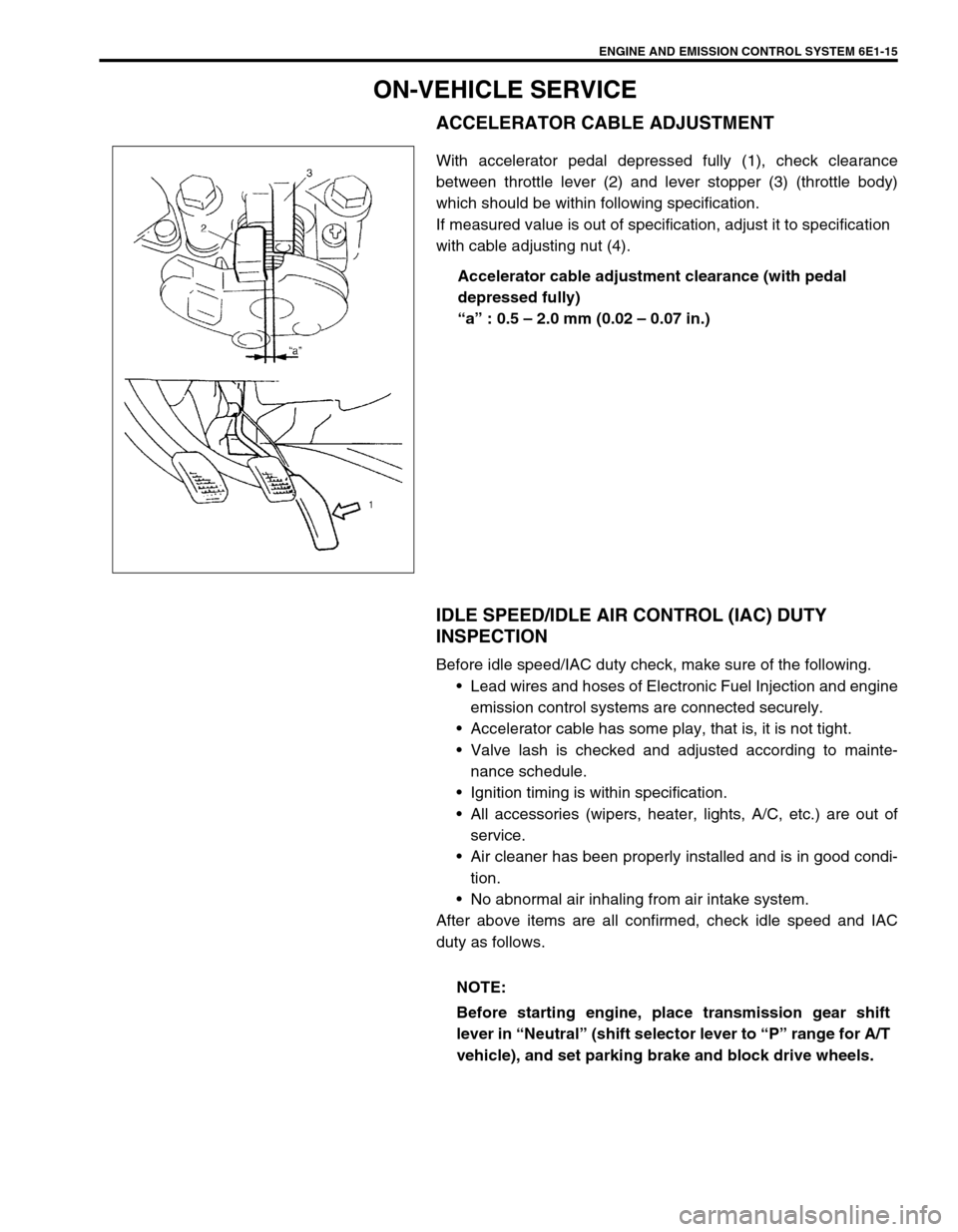
With accelerator pedal depressed fully (1), check clearance
between throttle lever (2) and lever stopper (3) (throttle body)
which should be within following specification.
If measured value is out of specification, adjust it to specification
with cable adjusting nut (4).
Accelerator cable adjustment clearance (with pedal
depressed fully)
“a” : 0.5 – 2.0 mm (0.02 – 0.07 in.)
IDLE SPEED/IDLE AIR CONTROL (IAC) DUTY
INSPECTION
Before idle speed/IAC duty check, make sure of the following.
Lead wires and hoses of Electronic Fuel Injection and engine
emission control systems are connected securely.
Accelerator cable has some play, that is, it is not tight.
Valve lash is checked and adjusted according to mainte-
nance schedule.
Ignition timing is within specification.
All accessories (wipers, heater, lights, A/C, etc.) are out of
service.
Air cleaner has been properly installed and is in good condi-
tion.
No abnormal air inhaling from air intake system.
After above items are all confirmed, check idle speed and IAC
duty as follows.
NOTE:
Before starting engine, place transmission gear shift
lever in “Neutral” (shift selector lever to “P” range for A/T
vehicle), and set parking brake and block drive wheels.
Page 637 of 698

6E1-16 ENGINE AND EMISSION CONTROL SYSTEM
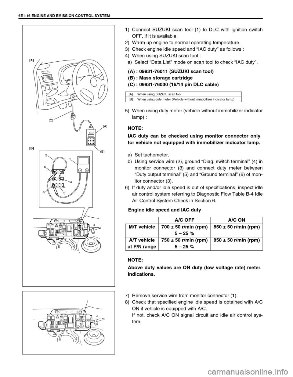
1) Connect SUZUKI scan tool (1) to DLC with ignition switch
OFF, if it is available.
2) Warm up engine to normal operating temperature.
3) Check engine idle speed and “IAC duty” as follows :
4) When using SUZUKI scan tool :
a) Select “Data List” mode on scan tool to check “IAC duty”.
(A) : 09931-76011 (SUZUKI scan tool)
(B) : Mass storage cartridge
(C) : 09931-76030 (16/14 pin DLC cable)
5) When using duty meter (vehicle without immobilizer indicator
lamp) :
a) Set tachometer.
b) Using service wire (2), ground “Diag. switch terminal” (4) in
monitor connector (3) and connect duty meter between
“Duty output terminal” (5) and “Ground terminal” (6) of mon-
itor connector (3).
6) If duty and/or idle speed is out of specifications, inspect idle
air control system referring to Diagnostic Flow Table B-4 Idle
Air Control System Check in Section 6.
Engine idle speed and IAC duty
7) Remove service wire from monitor connector (1).
8) Check that specified engine idle speed is obtained with A/C
ON if vehicle is equipped with A/C.
If not, check A/C ON signal circuit and idle air control sys-
tem.
[A] : When using SUZUKI scan tool
[B] : When using duty meter (Vehicle without immobilizer indicator lamp)
NOTE:
IAC duty can be checked using monitor connector only
for vehicle not equipped with immobilizer indicator lamp.
A/C OFF A/C ON
M/T vehicle 700 ± 50 r/min (rpm)
5 – 25 %850 ± 50 r/min (rpm)
A/T vehicle
at P/N range750 ± 50 r/min (rpm)
5 – 25 %850 ± 50 r/min (rpm)
NOTE:
Above duty values are ON duty (low voltage rate) meter
indications.
(C)
(A)
(B)
1 2
6
54
3-+
[A]
[B]
1