Page 234 of 698
REAR SUSPENSION 3E-21
2) Press-fit wheel bearing (1) with it’s seal side facing back
plate side using special tools and hydraulic press.
Special tool
(A) : 09913-76010
(B) : 09924-84510-004
3) Install bearing circlip (1) using special tool.
Special tool
(A) : 09900-06108
4) Install wheel sensor ring (if equipped with ABS).
Refer to “REAR WHEEL SENSOR RING” of Section 5E.
5) Install brake drum and wheel. For details, refer to “REAR
BRAKE DRUM” in Section 5.
REAR AXLE SHAFT AND WHEEL BEARING
(4WD VEHICLE)
REMOVAL
1) Hoist vehicle and remove rear wheels.
2) Remove rear brake drum. For details referring to Section 5.
3) Drain gear oil from rear axle housing by loosening drain plug
(1).
1. 8mm bolt
2. Level plug
Page 237 of 698

3E-24 REAR SUSPENSION
2) Press in a new bearing (2) and retainer ring (3) in order by
using an hydraulic press (4).
3) Install wheel sensor ring (if equipped with ABS).
Refer to “REAR WHEEL SENSOR RING” of Section 5E.
4) Inspect axle shaft length.
Rear axle shaft length “a”
Left side : 657.5 mm (25.9 in.)
Right side : 785.5 mm (30.9 in.)
5) Apply grease to axle shaft oil seal (1) lip as shown.
“A” : Grease 99000-25010
6) Apply sealant to mating surface of axle housing (2) with
brake back plate.
“B” : Sealant 99000-31090
7) Install rear axle shaft to rear axle housing and tighten brake
back plate bolts to specified torque.
Tightening torque
Brake back plate bolts (a) : 23 N·m (2.3 kg-m, 17.0 lb-ft) NOTE:
Install wheel bearing spacer (1) with the tapered side of
its inner diameter directed toward outside, or brake
drum side.
Install wheel bearing with its sealed side directed
toward brake drum side.
Use care not to cause any damage to outside of
retainer ring.
A : Tapered side
B : Sealed side
C : Differential side
D : Without ABS
E : With ABS
NOTE:
Make sure to remove old sealant before applying it anew.
NOTE:
When installing rear axle shaft, be careful not to cause
damage to oil seal lip in axle housing.
Page 238 of 698

REAR SUSPENSION 3E-25
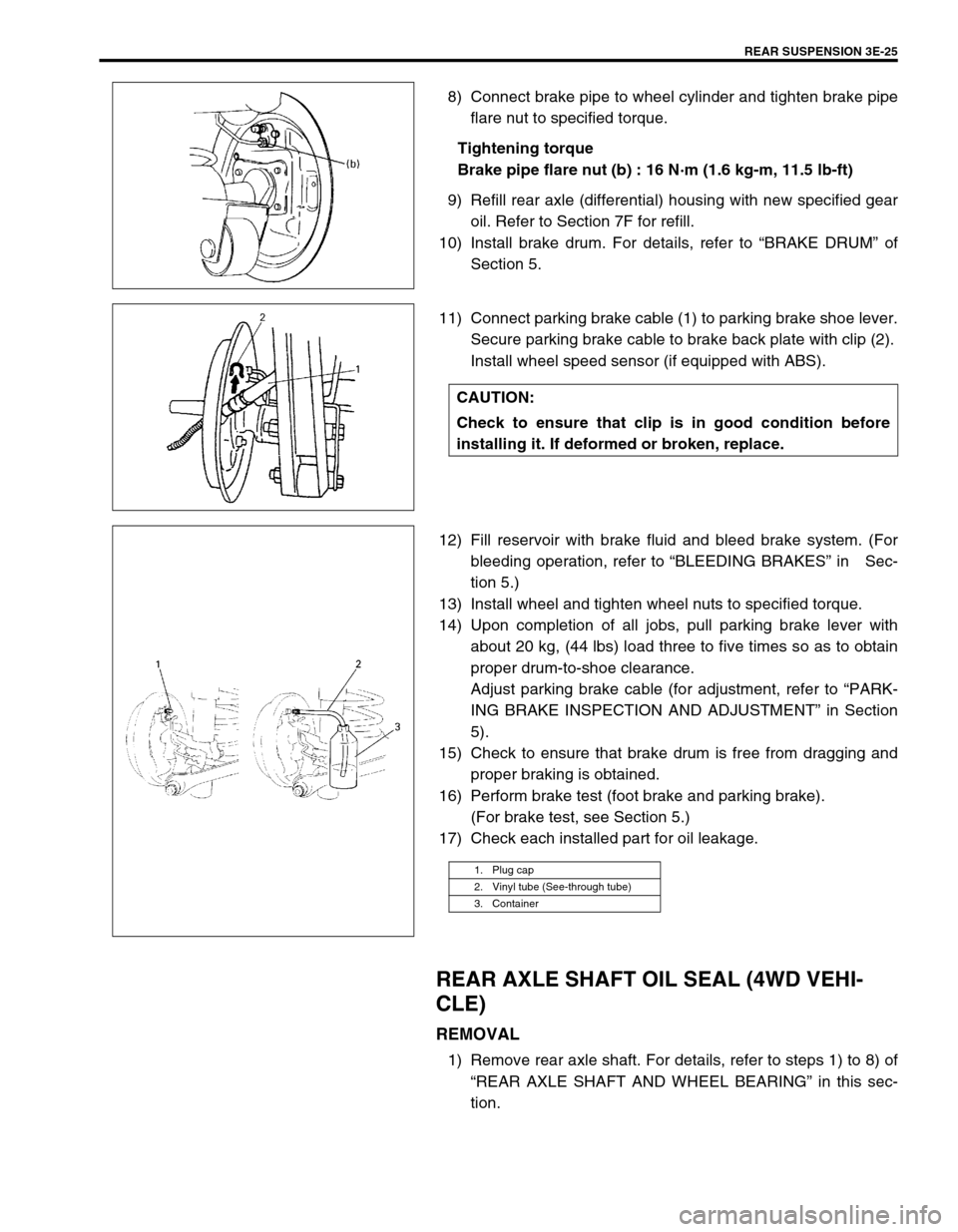
8) Connect brake pipe to wheel cylinder and tighten brake pipe
flare nut to specified torque.
Tightening torque
Brake pipe flare nut (b) : 16 N·m (1.6 kg-m, 11.5 lb-ft)
9) Refill rear axle (differential) housing with new specified gear
oil. Refer to Section 7F for refill.
10) Install brake drum. For details, refer to “BRAKE DRUM” of
Section 5.
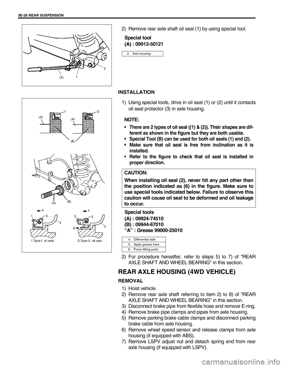
11) Connect parking brake cable (1) to parking brake shoe lever.
Secure parking brake cable to brake back plate with clip (2).
Install wheel speed sensor (if equipped with ABS).
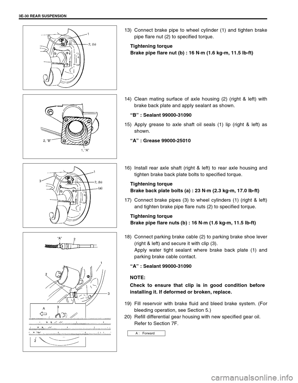
12) Fill reservoir with brake fluid and bleed brake system. (For
bleeding operation, refer to “BLEEDING BRAKES” in Sec-
tion 5.)
13) Install wheel and tighten wheel nuts to specified torque.
14) Upon completion of all jobs, pull parking brake lever with
about 20 kg, (44 lbs) load three to five times so as to obtain
proper drum-to-shoe clearance.
Adjust parking brake cable (for adjustment, refer to “PARK-
ING BRAKE INSPECTION AND ADJUSTMENT” in Section
5).
15) Check to ensure that brake drum is free from dragging and
proper braking is obtained.
16) Perform brake test (foot brake and parking brake).
(For brake test, see Section 5.)
17) Check each installed part for oil leakage.
REAR AXLE SHAFT OIL SEAL (4WD VEHI-
CLE)
REMOVAL
1) Remove rear axle shaft. For details, refer to steps 1) to 8) of
“REAR AXLE SHAFT AND WHEEL BEARING” in this sec-
tion.
CAUTION:
Check to ensure that clip is in good condition before
installing it. If deformed or broken, replace.
1. Plug cap
2. Vinyl tube (See-through tube)
3. Container
Page 239 of 698

3E-26 REAR SUSPENSION
2) Remove rear axle shaft oil seal (1) by using special tool.
Special tool
(A) : 09913-50121
INSTALLATION
1) Using special tools, drive in oil seal (1) or (2) until it contacts
oil seal protector (3) in axle housing.
Special tools
(A) : 09924-74510
(B) : 09944-67010
“A” : Grease 99000-25010
2) For procedure hereafter, refer to steps 5) to 7) of “REAR
AXLE SHAFT AND WHEEL BEARING” in this section.
REAR AXLE HOUSING (4WD VEHICLE)
REMOVAL
1) Hoist vehicle.
2) Remove rear axle shaft referring to item 2) to 8) of “REAR
AXLE SHAFT AND WHEEL BEARING” in this section.
3) Disconnect brake pipe from flexible hose and remove E-ring.
4) Remove brake pipe clamps and pipes from axle housing.
5) Remove parking brake cable clamps and disconnect parking
brake cable from axle housing.
6) Remove wheel speed sensor and release clamps from axle
housing (if equipped with ABS).
7) Remove LSPV adjust nut and detach spring end from rear
axle housing (if equipped with LSPV).
2. Axle housing
NOTE:
There are 2 types of oil seal ((1) & (2)). Their shapes are dif-
ferent as shown in the figure but they are both usable.
Special Tool (B) can be used for both oil seals (1) and (2).
Make sure that oil seal is free from inclination as it is
installed.
Refer to the figure to check that oil seal is installed in
proper direction.
CAUTION:
When installing oil seal (2), never hit any part other than
the position indicated as (6) in the figure. Make sure to
use special tools indicated below. Failure to observe this
caution will cause oil seal to be deformed and oil leakage
to occur.
4. Differential side
5. Apply grease here
6. Press-fitting point
Page 240 of 698
REAR SUSPENSION 3E-27
8) For jobs hereafter, support rear axle housing by using floor
jack (1) under axle housing (2).
9) Before removing propeller shaft, give match marks (1) on
joint flange and propeller shaft (2) as shown.
Remove propeller shaft.
10) Remove differential carrier assembly (3).
11) Remove lateral rod (1).
12) Loosen front and rear mounting nuts (3) of trailing arm but
don’t remove bolts.
13) Remove shock absorber (1) lower mounting bolt (2).
14) Lower floor jack until tension of suspension coil spring
becomes a little loose and remove rear mount bolts of trail-
ing arm.
15) Lower rear axle housing gradually and remove coil spring.
Page 241 of 698
3E-28 REAR SUSPENSION
16) Remove axle housing.
INSTALLATION
Install removed parts in reverse order of removal, noting the fol-
lowing.
1) Place rear axle housing on floor jack. Then install rear trail-
ing arm bolts (1) (right & left) in proper direction as shown. At
this time, mount nuts (2) but don’t tighten them.
2) Install coil springs (3) (right & left) on spring seat (2) of axle
housing (1) and raise axle housing.
3) Install lower part of shock absorber (1) to right and left sides
of axle housing and install bolts in proper direction as shown.
At this time, mount bolts (3) (right & left) but don’t tighten
them.
A : Vehicle out side
B : Vehicle center side
NOTE:
Upper and lower diameters of coil spring are different.
Bring lager diameter end at bottom and set its open end
in place on spring seat.
4. Stopped part
A : Upper side
2. Rear axle housing
Page 243 of 698

3E-30 REAR SUSPENSION
13) Connect brake pipe to wheel cylinder (1) and tighten brake
pipe flare nut (2) to specified torque.
Tightening torque
Brake pipe flare nut (b) : 16 N·m (1.6 kg-m, 11.5 lb-ft)
14) Clean mating surface of axle housing (2) (right & left) with
brake back plate and apply sealant as shown.
“B” : Sealant 99000-31090
15) Apply grease to axle shaft oil seals (1) lip (right & left) as
shown.
“A” : Grease 99000-25010
16) Install rear axle shaft (right & left) to rear axle housing and
tighten brake back plate bolts to specified torque.
Tightening torque
Brake back plate bolts (a) : 23 N·m (2.3 kg-m, 17.0 lb-ft)
17) Connect brake pipes (3) to wheel cylinders (1) (right & left)
and tighten brake pipe flare nuts (2) to specified torque.
Tightening torque
Brake pipe flare nuts (b) : 16 N·m (1.6 kg-m, 11.5 lb-ft)
18) Connect parking brake cable (2) to parking brake shoe lever
(right & left) and secure it with clip (3).
Apply water tight sealant where brake back plate (1) and
parking brake cable contact.
“A” : Sealant 99000-31090
19) Fill reservoir with brake fluid and bleed brake system. (For
bleeding operation, see Section 5.)
20) Refill differential gear housing with new specified gear oil.
Refer to Section 7F.
NOTE:
Check to ensure that clip is in good condition before
installing it. If deformed or broken, replace.
A : Forward
Page 244 of 698

REAR SUSPENSION 3E-31
21) Install wheel and tighten wheel nuts to specified torque.
Tightening torque
Wheel nuts (f) : 85 N·m (8.5 kg-m, 61.5 lb-ft)
22) Upon completion of all jobs, pull parking brake lever with
about 20 kg, (44 lbs) load three to five times so as to obtain
proper drum-to-shoe clearance.
Adjust parking brake cable (for adjustment, see Section 5.)
23) Lower hoist.
24) Tighten right and left trailing arm bolts and nuts (1) and
shock absorber lower bolts (2) to specified torque.
Tighten lateral rod bolt and nut (3) to specified torque.
Tightening torque
Rear trailing arm bolts (a) : 80 N·m (8.0 kg-m, 58.0 lb-ft)
Rear shock absorber lower bolts
(b) : 58 N·m (5.8 kg-m, 42.0 lb-ft)
Lateral rod axle housing side nut
(c) : 50 N·m (5.0 kg-m, 36.5 lb-ft)
Lateral rod body side nut (d) : 65 N·m (6.5 kg-m, 47.0 lb-ft)
25) Check to ensure that brake drum is free from dragging and
proper braking is obtained.
26) Perform brake test (foot brake and parking brake).
(For brake test, see Section 5.)
27) If equipped with LSPV, check and adjust LSPV spring refer-
ring to “LSPV INSPECTION AND ADJUSTMENT” and per-
form “FLUID PRESSURE TEST” in Section 5.
28) Check each installed part for oil leakage.
NOTE:
When tightening these bolts and nuts, be sure that vehi-
cle is off hoist and in non loaded condition.