Page 256 of 698
FRONT DRIVE SHAFT 4A-3
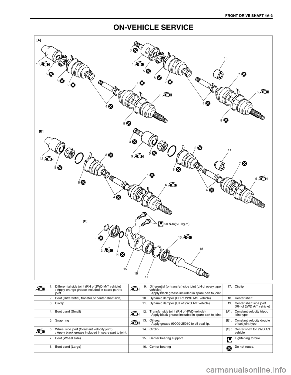
ON-VEHICLE SERVICE
1. Differential side joint (RH of 2WD M/T vehicle)
: Apply orange grease included in spare part to
joint.9. Differential (or transfer) side joint (LH of every type
vehicles)
: Apply black grease included in spare part to joint.17. Circlip
2. Boot (Differential, transfer or center shaft side) 10. Dynamic damper (RH of 2WD M/T vehicle) 18. Center shaft
3. Circlip 11. Dynamic damper (LH of 2WD A/T vehicle) 19. Center shaft side joint
(RH of 2WD A/T vehicle)
4. Boot band (Small) 12. Transfer side joint (RH of 4WD vehicle)
: Apply black grease included in spare part to joint.[A] : Constant velocity tripod
joint type
5. Snap ring 13. Oil seal
: Apply grease 99000-25010 to oil seal lip.[B] : Constant velocity double
offset joint type
6. Wheel side joint (Constant velocity joint)
: Apply black grease included in spare part to joint.14. Circlip [C] : Center shaft for 2WD A/T
vehicle
7. Boot (Wheel side) 15. Center bearing support Tightening torque
8. Boot band (Large) 16. Center bearing Do not reuse.
Page 257 of 698
4A-4 FRONT DRIVE SHAFT
DRIVE SHAFT ASSEMBLY
REMOVAL
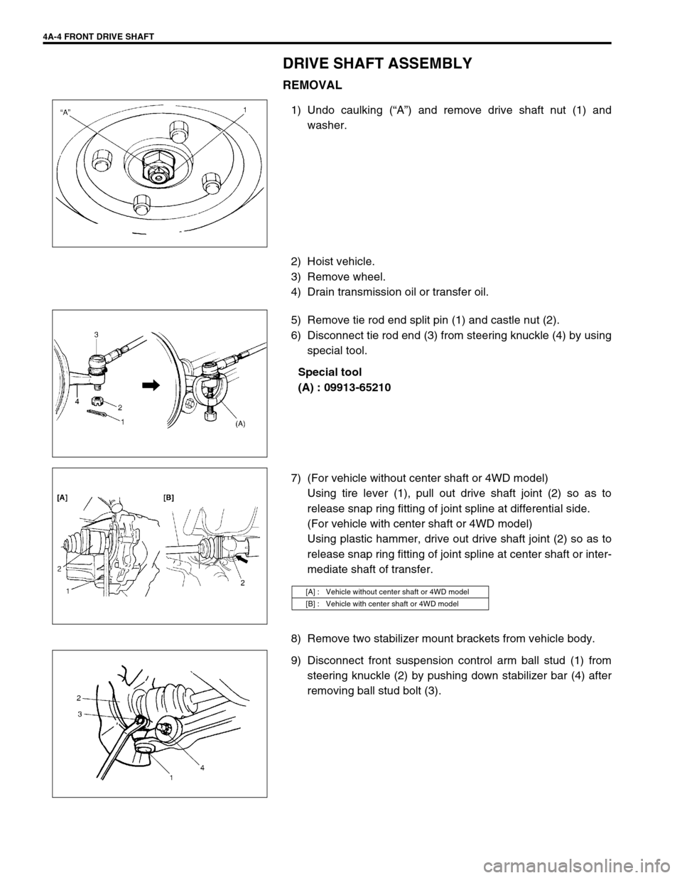
1) Undo caulking (“A”) and remove drive shaft nut (1) and
washer.
2) Hoist vehicle.
3) Remove wheel.
4) Drain transmission oil or transfer oil.
5) Remove tie rod end split pin (1) and castle nut (2).
6) Disconnect tie rod end (3) from steering knuckle (4) by using
special tool.
Special tool
(A) : 09913-65210
7) (For vehicle without center shaft or 4WD model)
Using tire lever (1), pull out drive shaft joint (2) so as to
release snap ring fitting of joint spline at differential side.
(For vehicle with center shaft or 4WD model)
Using plastic hammer, drive out drive shaft joint (2) so as to
release snap ring fitting of joint spline at center shaft or inter-
mediate shaft of transfer.
8) Remove two stabilizer mount brackets from vehicle body.
9) Disconnect front suspension control arm ball stud (1) from
steering knuckle (2) by pushing down stabilizer bar (4) after
removing ball stud bolt (3).
[A] : Vehicle without center shaft or 4WD model
[B] : Vehicle with center shaft or 4WD model
Page 260 of 698
FRONT DRIVE SHAFT 4A-7
4) Draw away cage (1) by using bearing puller (2), and remove
boot (3) from shaft.
5) Remove boot band, then pull out differential side boot from
shaft.
6) Pull out damper through shaft. (if equipped)
7) Undo boot bands of wheel side joint boot, then pull out boot
through shaft.
For Center Shaft and Center Bearing Support
1) Remove right side oil seal from center bearing support (1).
2) Remove circlip by using special tool.
Special tool
(A) : 09900-06108
3) Using hydraulic press (1), draw out center shaft (2) from cen-
ter bearing.
4) Remove left side oil seal from center bearing support (3).
CAUTION:
Do not disassemble wheel side joint. If any malcondition
is found in any joint, replace it as assembly.
Page 266 of 698
FRONT DRIVE SHAFT 4A-13
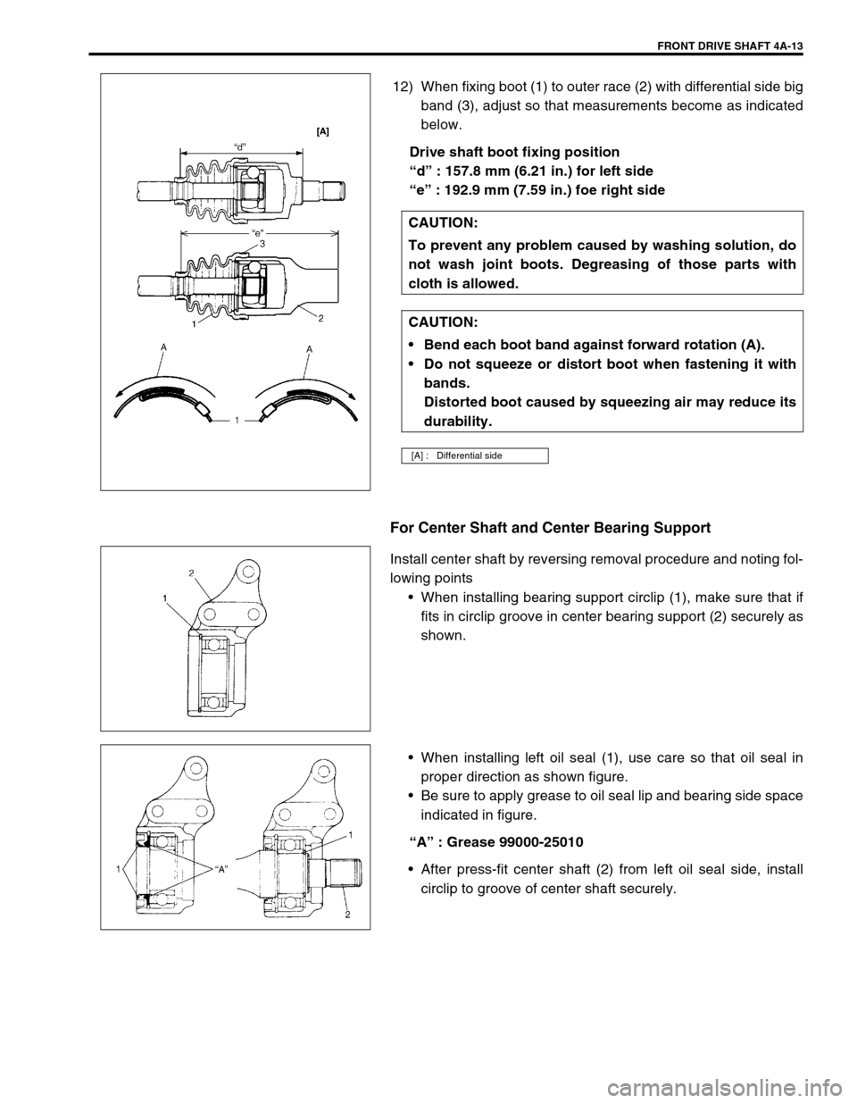
12) When fixing boot (1) to outer race (2) with differential side big
band (3), adjust so that measurements become as indicated
below.
Drive shaft boot fixing position
“d” : 157.8 mm (6.21 in.) for left side
“e” : 192.9 mm (7.59 in.) foe right side
For Center Shaft and Center Bearing Support
Install center shaft by reversing removal procedure and noting fol-
lowing points
When installing bearing support circlip (1), make sure that if
fits in circlip groove in center bearing support (2) securely as
shown.
When installing left oil seal (1), use care so that oil seal in
proper direction as shown figure.
Be sure to apply grease to oil seal lip and bearing side space
indicated in figure.
“A” : Grease 99000-25010
After press-fit center shaft (2) from left oil seal side, install
circlip to groove of center shaft securely. CAUTION:
To prevent any problem caused by washing solution, do
not wash joint boots. Degreasing of those parts with
cloth is allowed.
CAUTION:
Bend each boot band against forward rotation (A).
Do not squeeze or distort boot when fastening it with
bands.
Distorted boot caused by squeezing air may reduce its
durability.
[A] : Differential side
Page 267 of 698
4A-14 FRONT DRIVE SHAFT
When installing right oil seal (1), use care so that oil seal in
proper direction as shown figure.
Be sure apply grease to oil seal lip and bearing side space
indicated in figure.
“A” : Grease 99000-25010
INSTALLATION
Install drive shaft assembly by reversing removal procedure and
noting following points.
Clean front wheel bearing oil seal (1) and then apply grease.
Replace it if required.
“A” : Grease 99000-25010
CAUTION:
To avoid excessive expansion of boot and consequen-
tial disconnection of joint in boot, do not pull differen-
tial side joint housing.
Protect oil seals and boots from any damage, prevent-
ing them from unnecessary contact while installing
drive shaft.
Do not hit joint boot with hammer. Inserting joint only
by hands is allowed.
Make sure that differential side joint is inserted fully
and its snap ring is seated as it was.
Page 268 of 698
FRONT DRIVE SHAFT 4A-15
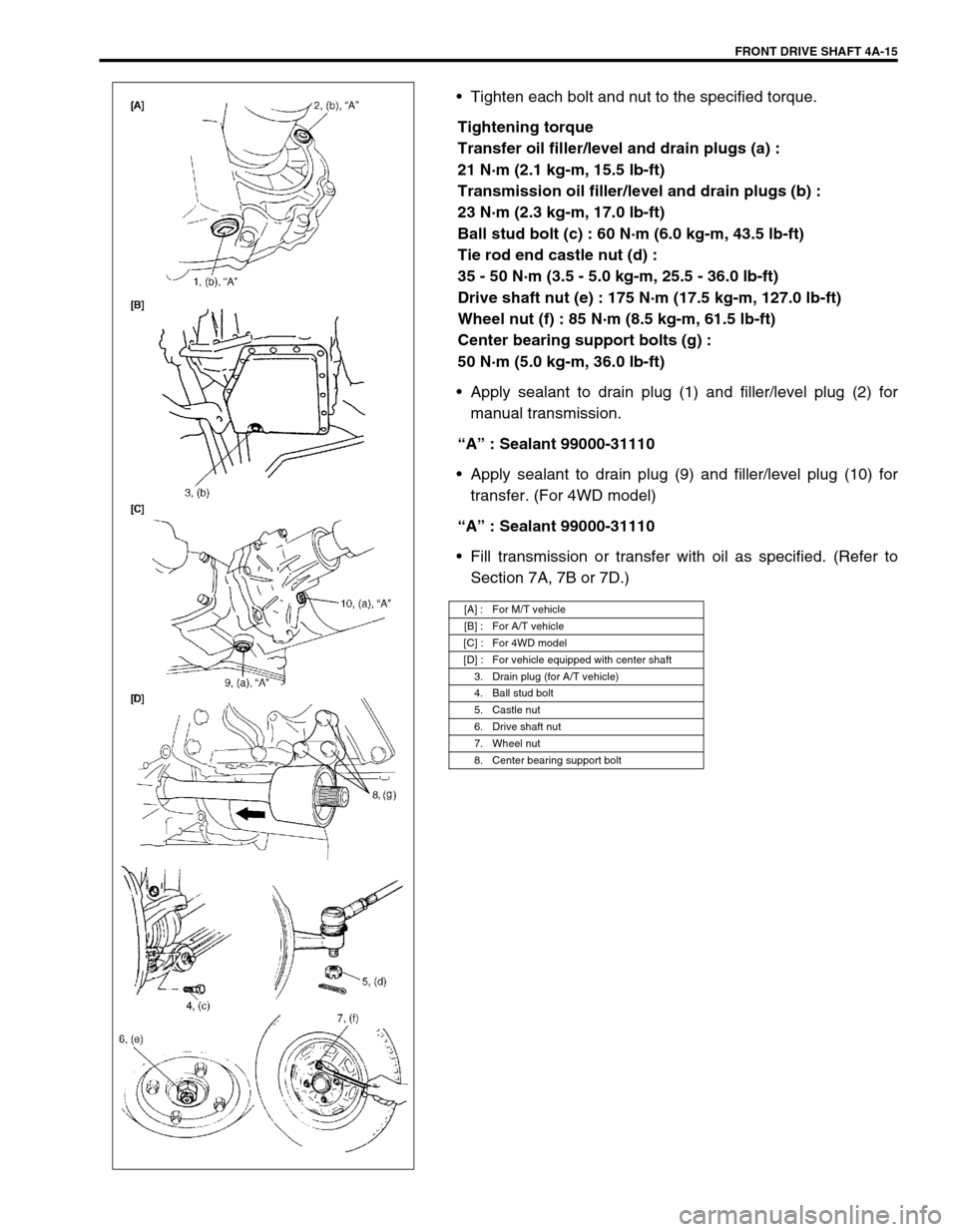
Tighten each bolt and nut to the specified torque.
Tightening torque
Transfer oil filler/level and drain plugs (a) :
21 N·m (2.1 kg-m, 15.5 lb-ft)
Transmission oil filler/level and drain plugs (b) :
23 N·m (2.3 kg-m, 17.0 lb-ft)
Ball stud bolt (c) : 60 N·m (6.0 kg-m, 43.5 lb-ft)
Tie rod end castle nut (d) :
35 - 50 N·m (3.5 - 5.0 kg-m, 25.5 - 36.0 lb-ft)
Drive shaft nut (e) : 175 N·m (17.5 kg-m, 127.0 lb-ft)
Wheel nut (f) : 85 N·m (8.5 kg-m, 61.5 lb-ft)
Center bearing support bolts (g) :
50 N·m (5.0 kg-m, 36.0 lb-ft)
Apply sealant to drain plug (1) and filler/level plug (2) for
manual transmission.
“A” : Sealant 99000-31110
Apply sealant to drain plug (9) and filler/level plug (10) for
transfer. (For 4WD model)
“A” : Sealant 99000-31110
Fill transmission or transfer with oil as specified. (Refer to
Section 7A, 7B or 7D.)
[A] : For M/T vehicle
[B] : For A/T vehicle
[C] : For 4WD model
[D] : For vehicle equipped with center shaft
3. Drain plug (for A/T vehicle)
4. Ball stud bolt
5. Castle nut
6. Drive shaft nut
7. Wheel nut
8. Center bearing support bolt
Page 269 of 698
4A-16 FRONT DRIVE SHAFT
TIGHTENING TORQUE SPECIFICATION
REQUIRED SERVICE MATERIAL
SPECIAL TOOL
Fastening portionTightening torque
Nm kg-m lb-ft
Transfer oil filler/level and drain plugs 21 2.1 15.5
Transmission oil filler/level and drain plugs 23 2.3 17.0
Ball stud bolt 60 6.0 43.5
Tie rod end castle nut 35 - 50 3.5 - 5.0 25.5 - 36.0
Drive shaft nut 175 17.5 127.0
Wheel nut 85 8.5 61.5
Center bearing support bolts 50 5.0 36.0
MaterialRecommended SUZUKI product
(Part Number)Use
Lithium grease SUZUKI SUPER GREASE A
(99000-25010)Oil seal lips
Sealant SUZUKI BOND NO. 1215
(99000-31110)Oil drain and filler plug for manual
transmission or transfer
09913-65210 09900-06107 09900-06108
Tie-rod end remover Snap ring pliers (Open
type)Snap ring pliers (Closing
type)
Page 277 of 698
5-4 BRAKES
DIAGNOSIS
ROAD TESTING BRAKES
Brakes should be tested on dry, clean, smooth and reasonably level roadway which is not crowned. Road test
brakes by making brake applications with both light and heavy pedal forces at various speeds to determine if the
vehicle stops evenly and effectively. Also drive vehicle to see if it leads to one side or the other without brake
application. If it does, check the tire pressure, front end alignment and front suspension attachments for loose-
ness. See diagnosis table for other causes.
BRAKE FLUID LEAKS
Check the master cylinder fluid levels. While a slight drop in reservoir level does result from normal lining wear,
an abnormally low level indicates a leak in the system. In such a case, check the entire brake system for leak-
age. If even a slight evidence of leakage is noted, the cause should be corrected or defective parts should be
replaced.
SUBSTANDARD OR CONTAMINATED BRAKE FLUID
Improper brake fluid, mineral oil or water in the fluid may cause the brake fluid to boil or the rubber components
in the hydraulic system to deteriorate.
If primary piston cups are swollen, then rubber parts have deteriorated. This deterioration may also be evi-
denced by swollen wheel cylinder piston cups on the drum brake wheels.
If deterioration of rubber is evident, disassemble all hydraulic parts and wash with alcohol. Dry these parts with
compressed air before assembly to keep alcohol out of the system. Replace all rubber parts in the system,
including hoses. Also, when working on the brake mechanisms, check for fluid on the linings.
If excessive fluid is found, replace the pads.
If master cylinder piston seals are satisfactory, check for leakage or excessive heat conditions. If leakage is not
found, drain fluid, flush with brake fluid, refill and bleed system.
The system must be flushed if there is any doubt as to the grade of fluid in the system or if fluid has been used
which contained parts that have been subjected to contaminated fluid.