Page 108 of 698
AIR CONDITIONING (OPTIONAL) 1B-43
6) Tighten new front head mounting bolts (a), (b).
Tightening torque
Front head bolt (a) : 9 N·m (0.9 kg-m, 6.5 lb-ft)
Front head bolt (b) : 22 N·m (2.2 kg-m, 16.0 lb-ft)
REQUIRED SERVICE MATERIAL
NOTE:
Be sure to use new front head mounting bolts.
Tighten bolt (a) first, and next (b).
MaterialRecommended SUZUKI product
(Part Number)Use
Compressor oil
(Refrigerant oil)COMPRESSOR OIL RS20 (150 cc)
99000-99088O-ring
Each component
Refrigerant REFRIGERANT DRUM (200 g)
95794-50G00Refrigerant charge
Sealant SUZUKI BOND No.1216B
99000-31160Cooling unit
Page 113 of 698

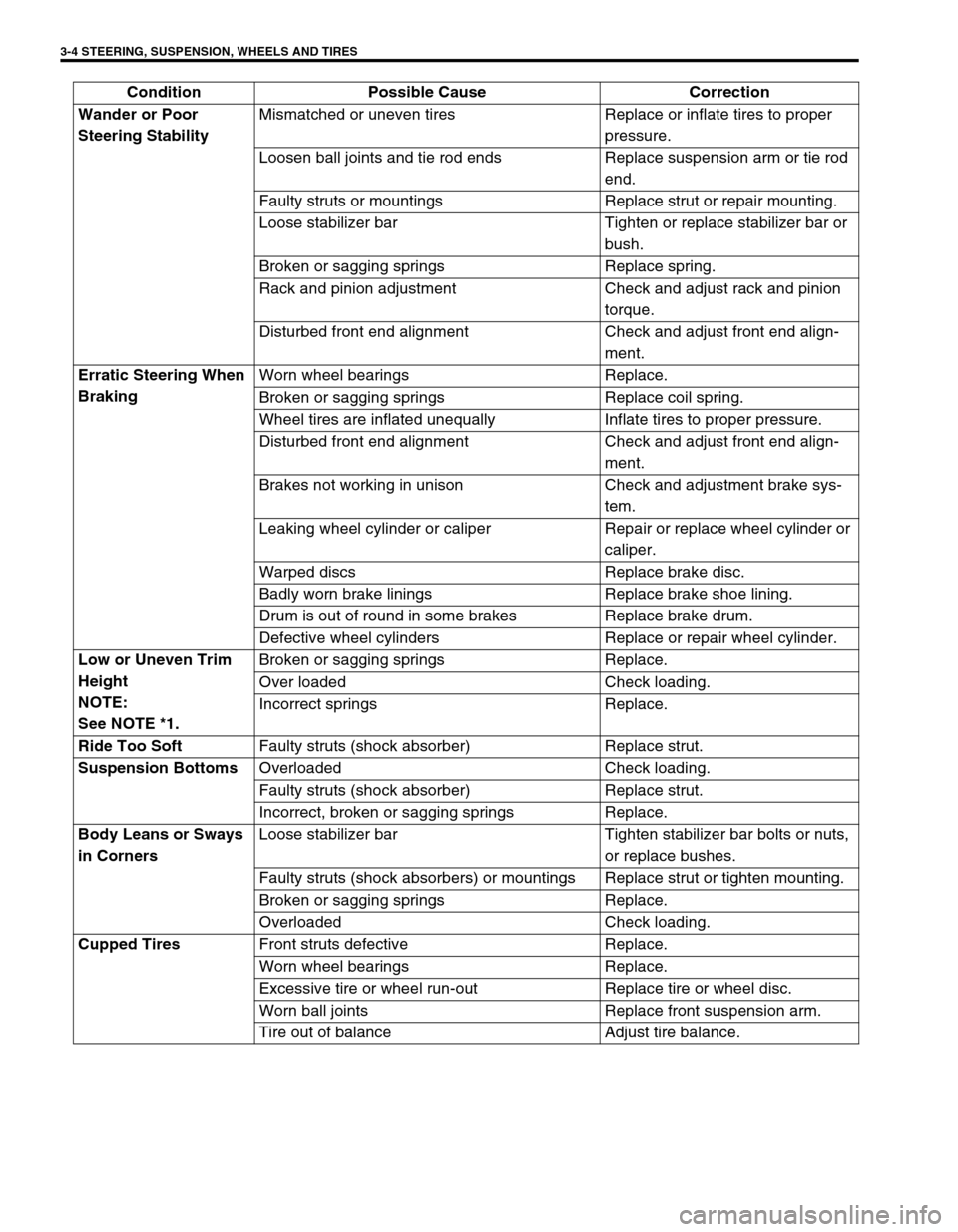
3-4 STEERING, SUSPENSION, WHEELS AND TIRES
Wander or Poor
Steering StabilityMismatched or uneven tires Replace or inflate tires to proper
pressure.
Loosen ball joints and tie rod ends Replace suspension arm or tie rod
end.
Faulty struts or mountings Replace strut or repair mounting.
Loose stabilizer bar Tighten or replace stabilizer bar or
bush.
Broken or sagging springs Replace spring.
Rack and pinion adjustment Check and adjust rack and pinion
torque.
Disturbed front end alignment Check and adjust front end align-
ment.
Erratic Steering When
BrakingWorn wheel bearings Replace.
Broken or sagging springs Replace coil spring.
Wheel tires are inflated unequally Inflate tires to proper pressure.
Disturbed front end alignment Check and adjust front end align-
ment.
Brakes not working in unison Check and adjustment brake sys-
tem.
Leaking wheel cylinder or caliper Repair or replace wheel cylinder or
caliper.
Warped discs Replace brake disc.
Badly worn brake linings Replace brake shoe lining.
Drum is out of round in some brakes Replace brake drum.
Defective wheel cylinders Replace or repair wheel cylinder.
Low or Uneven Trim
Height
NOTE:
See NOTE *1.Broken or sagging springs Replace.
Over loaded Check loading.
Incorrect springs Replace.
Ride Too Soft
Faulty struts (shock absorber) Replace strut.
Suspension Bottoms
Overloaded Check loading.
Faulty struts (shock absorber) Replace strut.
Incorrect, broken or sagging springs Replace.
Body Leans or Sways
in CornersLoose stabilizer bar Tighten stabilizer bar bolts or nuts,
or replace bushes.
Faulty struts (shock absorbers) or mountings Replace strut or tighten mounting.
Broken or sagging springs Replace.
Overloaded Check loading.
Cupped Tires
Front struts defective Replace.
Worn wheel bearings Replace.
Excessive tire or wheel run-out Replace tire or wheel disc.
Worn ball joints Replace front suspension arm.
Tire out of balance Adjust tire balance. Condition Possible Cause Correction
Page 128 of 698

MANUAL RACK AND PINION 3B-7
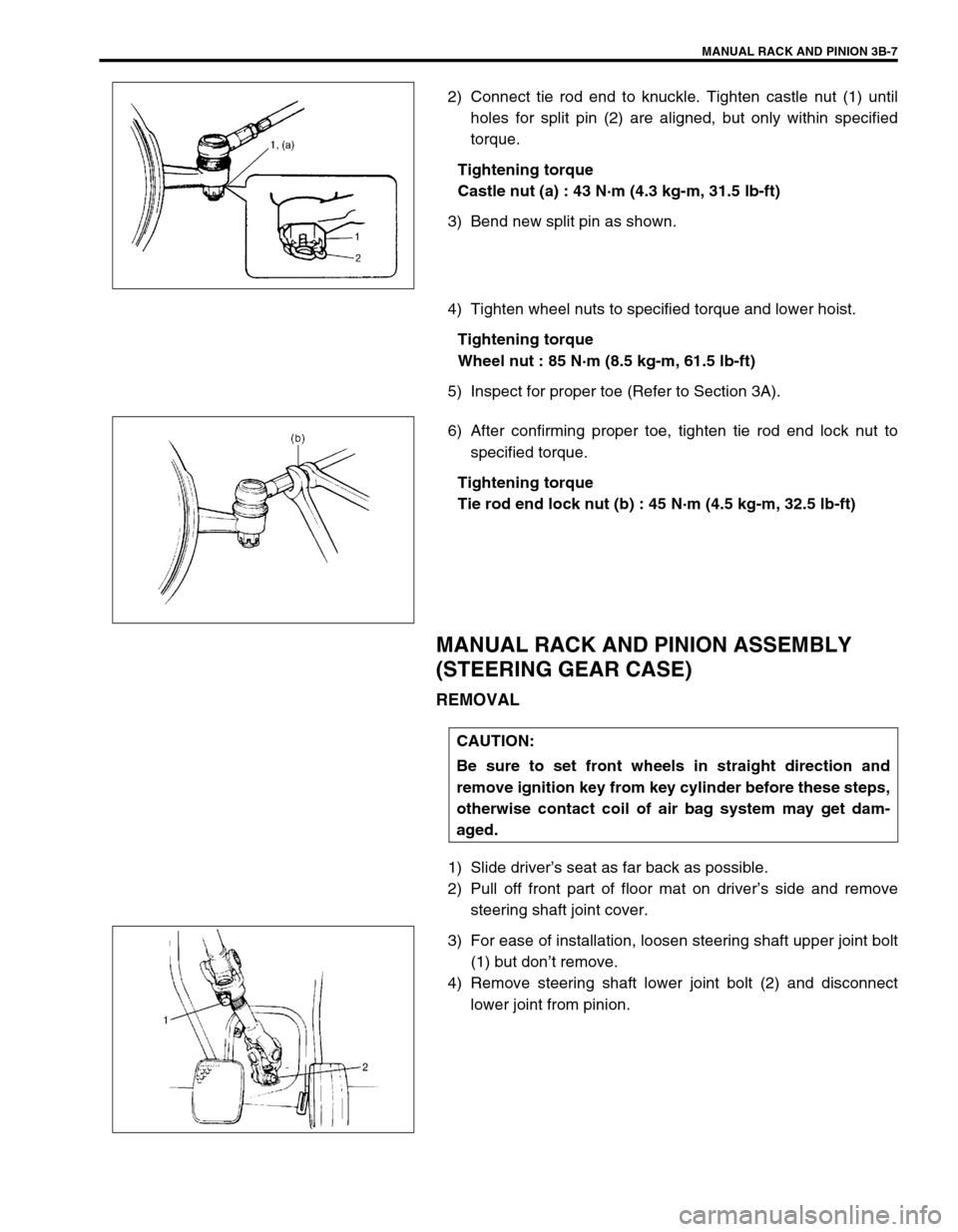
2) Connect tie rod end to knuckle. Tighten castle nut (1) until
holes for split pin (2) are aligned, but only within specified
torque.
Tightening torque
Castle nut (a) : 43 N·m (4.3 kg-m, 31.5 lb-ft)
3) Bend new split pin as shown.
4) Tighten wheel nuts to specified torque and lower hoist.
Tightening torque
Wheel nut : 85 N·m (8.5 kg-m, 61.5 lb-ft)
5) Inspect for proper toe (Refer to Section 3A).
6) After confirming proper toe, tighten tie rod end lock nut to
specified torque.
Tightening torque
Tie rod end lock nut (b) : 45 N·m (4.5 kg-m, 32.5 lb-ft)
MANUAL RACK AND PINION ASSEMBLY
(STEERING GEAR CASE)
REMOVAL
1) Slide driver’s seat as far back as possible.
2) Pull off front part of floor mat on driver’s side and remove
steering shaft joint cover.
3) For ease of installation, loosen steering shaft upper joint bolt
(1) but don’t remove.
4) Remove steering shaft lower joint bolt (2) and disconnect
lower joint from pinion.
CAUTION:
Be sure to set front wheels in straight direction and
remove ignition key from key cylinder before these steps,
otherwise contact coil of air bag system may get dam-
aged.
Page 135 of 698
3B-14 MANUAL RACK AND PINION
STEERING PINION
REMOVAL
1) Remove rack plunger as shown in STEERING RACK
PLUNGER.
2) Remove bearing plug with special tool.
Special tool
(A) : 09944-26011
3) Tap on position as shown with plastic hammer (2) to sepa-
rate pinion assembly (1) from housing, and remove pinion
assembly.
4) Remove oil seal (2) with special tool from pinion bearing plug
(1).
Special tool
(B) : 09913-50121
INSPECTION
Inspect pinion teeth surface (3) for wear or damage.
Inspect oil seal (1) for damage.
Replace any part found defective.
Check rotation condition of bearing and inspect for wear.
If found defective, replace.
2. Case seal
Page 136 of 698
MANUAL RACK AND PINION 3B-15
INSTALLATION
1) Install new oil seal with special tool to pinion bearing plug
(1).
Special tool
(C) : 09925-98210
2) Apply grease to all around pinion teeth (2), pinion needle
bearing, gear case O-ring (4) and gear case oil seal lip (1).
Fill inside of pinion bearing plug (3) with grease.
“A” : Grease 99000-25050
3) Install pinion assembly and after applying sealant to pinion
bearing plug (5) thread as shown.
“B” : Sealant 99000-31150
4) Tighten pinion bearing plug to specified torque.
Tightening torque
Pinion bearing plug (a) : 95 N·m (9.5 kg-m, 69.0 lb-ft)
Special tool
(D) : 09944-26011
5) Install rack plunger in STEERING RACK PLUNGER.
STEERING RACK
REMOVAL
1) Remove steering gear case.
2) Remove boot wires (2) and clips (1).
3) Move both boots toward tie rod end.
Page 140 of 698

MANUAL RACK AND PINION 3B-19
INSTALLATION
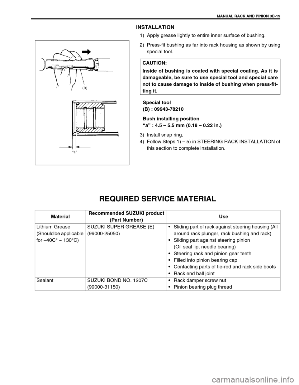
1) Apply grease lightly to entire inner surface of bushing.
2) Press-fit bushing as far into rack housing as shown by using
special tool.
Special tool
(B) : 09943-78210
Bush installing position
“a” : 4.5 – 5.5 mm (0.18 – 0.22 in.)
3) Install snap ring.
4) Follow Steps 1) – 5) in STEERING RACK INSTALLATION of
this section to complete installation.
REQUIRED SERVICE MATERIAL
CAUTION:
Inside of bushing is coated with special coating. As it is
damageable, be sure to use special tool and special care
not to cause damage to inside of bushing when press-fit-
ting it.
MaterialRecommended SUZUKI product
(Part Number)Use
Lithium Grease
(Should be applicable
for –40C° ~ 130°C)SUZUKI SUPER GREASE (E)
(99000-25050)Sliding part of rack against steering housing (All
around rack plunger, rack bushing and rack)
Sliding part against steering pinion
(Oil seal lip, needle bearing)
Steering rack and pinion gear teeth
Filled into pinion bearing cap
Contacting parts of tie-rod and rack side boots
Rack end ball joint
Sealant SUZUKI BOND NO. 1207C
(99000-31150)Rack damper screw nut
Pinion bearing plug thread
Page 141 of 698
3B-20 MANUAL RACK AND PINION
SPECIAL TOOL
09913-65210 09913-50121 09921-20200 09925-98210
Tie-rod end remover Oil seal remover Pinion bearing remover Bearing installer
09930-30102 09943-78210 09944-18211 09944-26011
Sliding shaft Rack bush installer Pinion torque checking
socket43 mm Socket (Pinion
bearing plug remover)
09944-48210
Rack bush remover
Page 151 of 698
3B1-10 ELECTRICAL POWER STEERING (P/S) SYSTEM
SERIAL DATA LINK CIRCUIT CHECK
DIAGNOSTIC FLOW TABLE
CAUTION:
Be sure to perform “SYSTEM CHECK FLOW TABLE” before starting diagnosis according to flow table.
1. Main fuse box 6. Combination meter 11. Data link connector (DLC)
2.“EPS” fuse (30 A) 7. Speedometer 12. To ECM, SDM and ABS hydraulic unit/control module
assembly (if equipped)
3. Ignition switch 8.“EPS” warning lamp 13. P/S control module
4. Circuit fuse box 9. To vehicle speed sensor (VSS) 14. Connector “G24”
5.“IG coil” fuse (15 A) 10. To main fuse box
Step Action Yes No
1Was “SYSTEM CHECK FLOW TABLE” per-
formed?Go to Step 2. Go to “SYSTEM CHECK
FLOW TABLE” in this sec-
tion.
2 1) Make sure that SUZUKI scan tool free from
malfunction and correct cartridge for P/S
system is used.
2) Turn ignition switch to OFF position.
3) Check proper connection of SUZUKI scan
tool to DLC.
Is connection in good condition?Go to Step 3. Properly connect SUZUKI
scan tool to DLC.