2000 NISSAN PATROL ecm
[x] Cancel search: ecmPage 29 of 1033
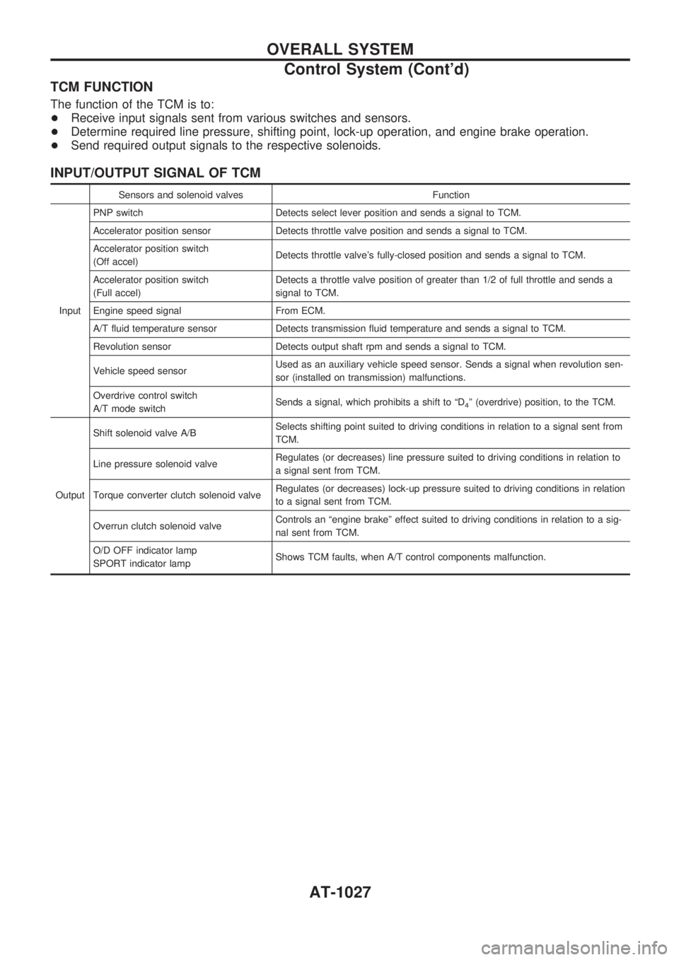
TCM FUNCTION
The function of the TCM is to:
+Receive input signals sent from various switches and sensors.
+Determine required line pressure, shifting point, lock-up operation, and engine brake operation.
+Send required output signals to the respective solenoids.
INPUT/OUTPUT SIGNAL OF TCM
Sensors and solenoid valves Function
InputPNP switch Detects select lever position and sends a signal to TCM.
Accelerator position sensor Detects throttle valve position and sends a signal to TCM.
Accelerator position switch
(Off accel)Detects throttle valve's fully-closed position and sends a signal to TCM.
Accelerator position switch
(Full accel)Detects a throttle valve position of greater than 1/2 of full throttle and sends a
signal to TCM.
Engine speed signal From ECM.
A/T fluid temperature sensor Detects transmission fluid temperature and sends a signal to TCM.
Revolution sensor Detects output shaft rpm and sends a signal to TCM.
Vehicle speed sensorUsed as an auxiliary vehicle speed sensor. Sends a signal when revolution sen-
sor (installed on transmission) malfunctions.
Overdrive control switch
A/T mode switchSends a signal, which prohibits a shift to ªD
4º (overdrive) position, to the TCM.
OutputShift solenoid valve A/BSelects shifting point suited to driving conditions in relation to a signal sent from
TCM.
Line pressure solenoid valveRegulates (or decreases) line pressure suited to driving conditions in relation to
a signal sent from TCM.
Torque converter clutch solenoid valveRegulates (or decreases) lock-up pressure suited to driving conditions in relation
to a signal sent from TCM.
Overrun clutch solenoid valveControls an ªengine brakeº effect suited to driving conditions in relation to a sig-
nal sent from TCM.
O/D OFF indicator lamp
SPORT indicator lampShows TCM faults, when A/T control components malfunction.
OVERALL SYSTEM
Control System (Cont'd)
AT-1027
Page 62 of 1033
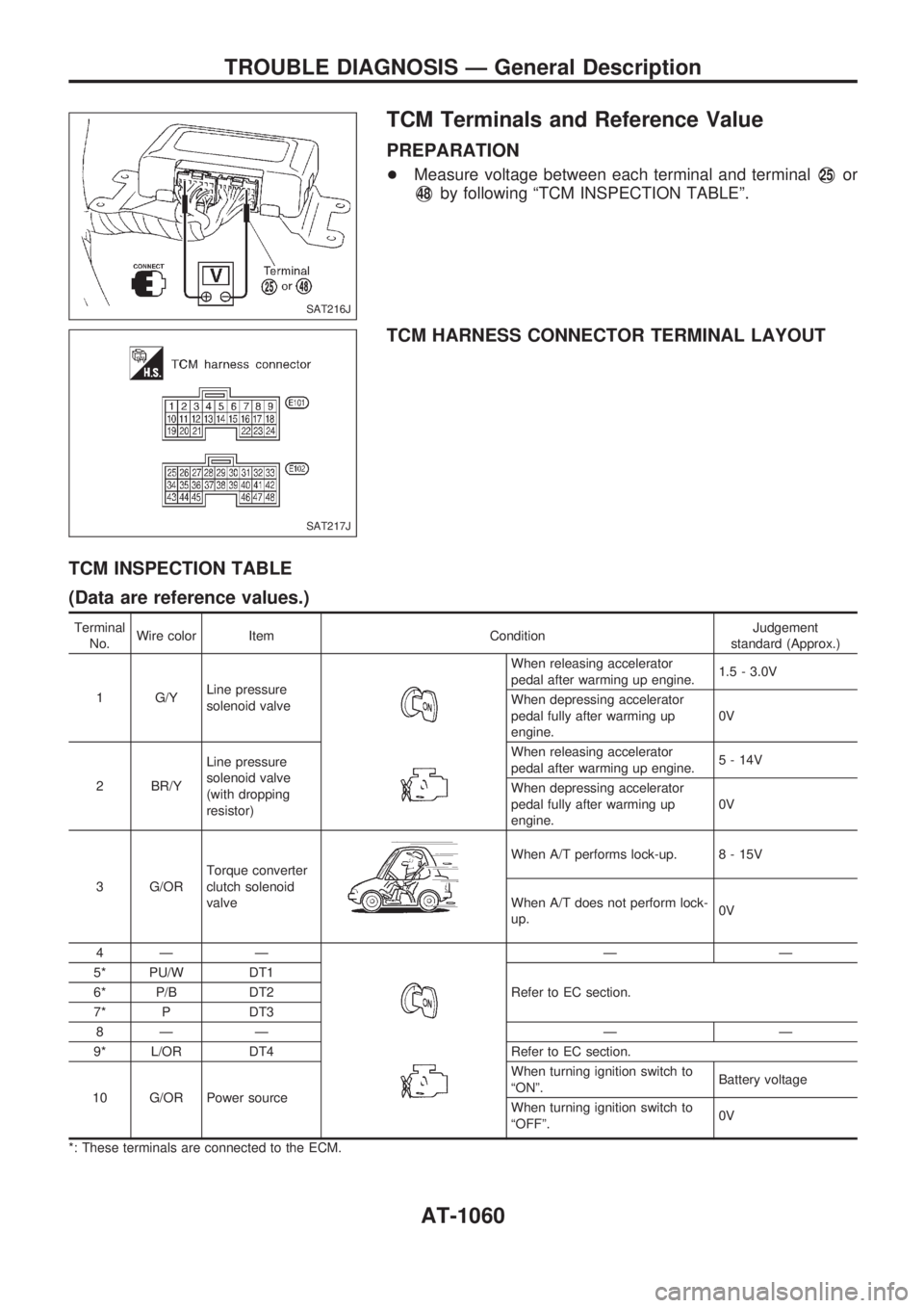
TCM Terminals and Reference Value
PREPARATION
+Measure voltage between each terminal and terminalV25or
V48by following ªTCM INSPECTION TABLEº.
TCM HARNESS CONNECTOR TERMINAL LAYOUT
TCM INSPECTION TABLE
(Data are reference values.)
Terminal
No.Wire color Item ConditionJudgement
standard (Approx.)
1 G/YLine pressure
solenoid valve
When releasing accelerator
pedal after warming up engine.1.5 - 3.0V
When depressing accelerator
pedal fully after warming up
engine.0V
2 BR/YLine pressure
solenoid valve
(with dropping
resistor)When releasing accelerator
pedal after warming up engine.5 - 14V
When depressing accelerator
pedal fully after warming up
engine.0V
3 G/ORTorque converter
clutch solenoid
valve
When A/T performs lock-up. 8 - 15V
When A/T does not perform lock-
up.0V
4Ð Ð
ÐÐ
5* PU/W DT1
Refer to EC section. 6* P/B DT2
7* P DT3
8Ð Ð Ð Ð
9* L/OR DT4 Refer to EC section.
10 G/OR Power sourceWhen turning ignition switch to
ªONº.Battery voltage
When turning ignition switch to
ªOFFº.0V
*: These terminals are connected to the ECM.
SAT216J
SAT217J
TROUBLE DIAGNOSIS Ð General Description
AT-1060
Page 63 of 1033
Terminal
No.Wire color Item ConditionJudgement
standard (Approx.)
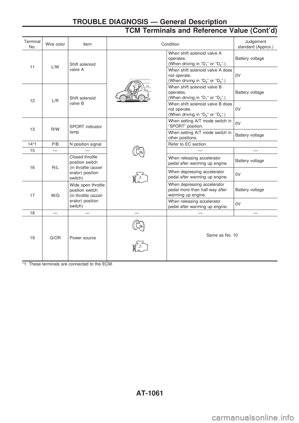
11 L/WShift solenoid
valve A
When shift solenoid valve A
operates.
(When driving in ªD
1ºorªD4º.)Battery voltage
When shift solenoid valve A does
not operate.
(When driving in ªD
2ºorªD3º.)0V
12 L/RShift solenoid
valve BWhen shift solenoid valve B
operates.
(When driving in ªD
1ºorªD2º.)Battery voltage
When shift solenoid valve B does
not operate.
(When driving in ªD
3ºorªD4º.)0V
13 R/WSPORT indicator
lamp
When setting A/T mode switch in
ªSPORTº position.0V
When setting A/T mode switch in
other positions.Battery voltage
14*1 P/B N position signal Refer to EC section.
15 Ð Ð Ð Ð
16 R/LClosed throttle
position switch
(in throttle (accel-
erator) position
switch)When releasing accelerator
pedal after warming up engine.Battery voltage
When depressing accelerator
pedal after warming up engine.0V
17 W/GWide open throttle
position switch
(in throttle (accel-
erator) position
switch)When depressing accelerator
pedal more than half-way after
warming up engine.Battery voltage
When releasing accelerator
pedal after warming up engine.0V
18 Ð Ð Ð Ð Ð
19 G/OR Power source
Same as No. 10
*1: These terminals are connected to the ECM.
TROUBLE DIAGNOSIS Ð General Description
TCM Terminals and Reference Value (Cont'd)
AT-1061
Page 67 of 1033
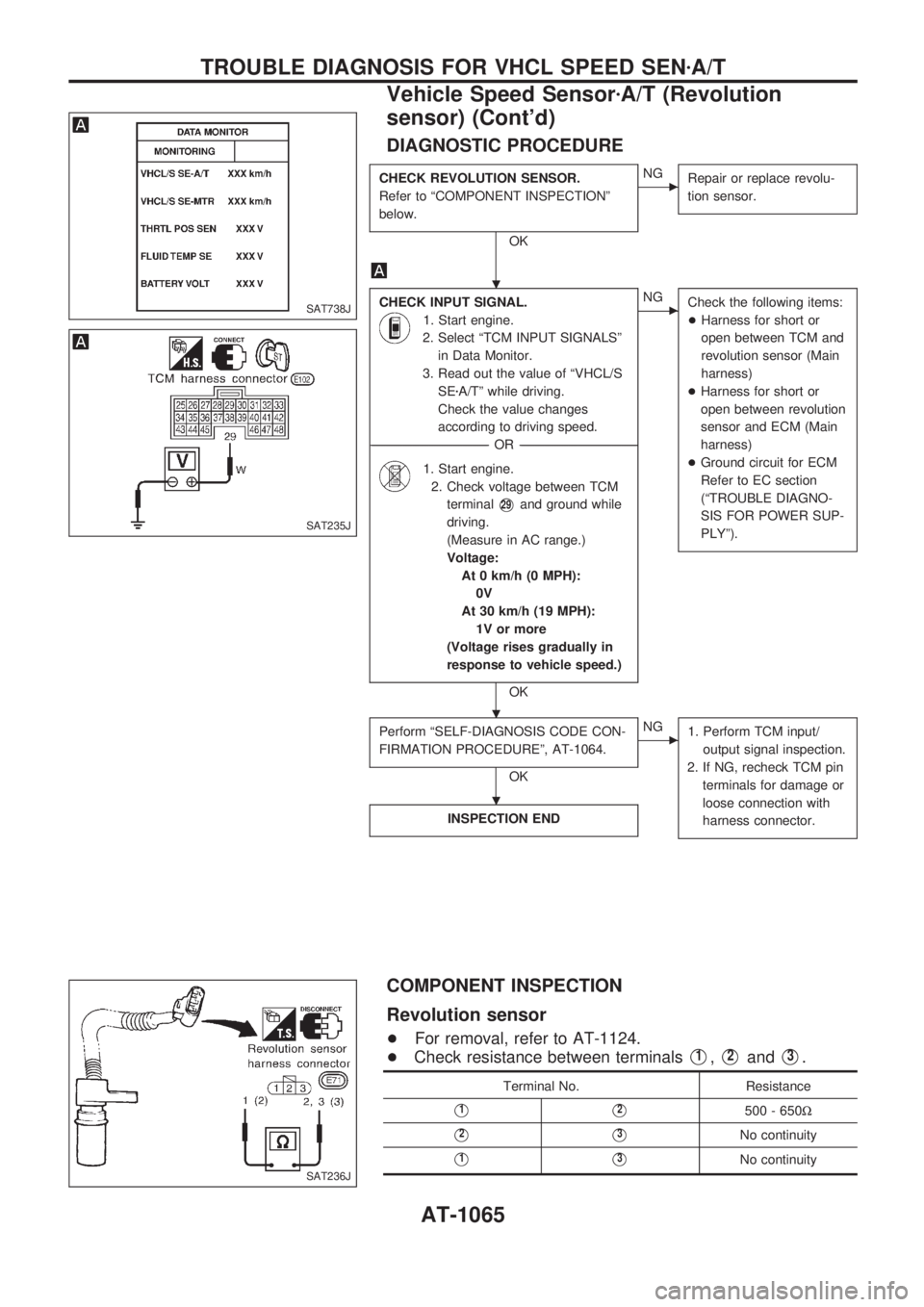
DIAGNOSTIC PROCEDURE
CHECK REVOLUTION SENSOR.
Refer to ªCOMPONENT INSPECTIONº
below.
OK
cNG
Repair or replace revolu-
tion sensor.
CHECK INPUT SIGNAL.
1. Start engine.
2. Select ªTCM INPUT SIGNALSº
in Data Monitor.
3. Read out the value of ªVHCL/S
SEzA/Tº while driving.
Check the value changes
according to driving speed.
------------------------------------------------------------------------------------------------------------------------------------OR------------------------------------------------------------------------------------------------------------------------------------
1. Start engine.
2. Check voltage between TCM
terminal
V29and ground while
driving.
(Measure in AC range.)
Voltage:
At 0 km/h (0 MPH):
0V
At 30 km/h (19 MPH):
1V or more
(Voltage rises gradually in
response to vehicle speed.)
OK
cNG
Check the following items:
+Harness for short or
open between TCM and
revolution sensor (Main
harness)
+Harness for short or
open between revolution
sensor and ECM (Main
harness)
+Ground circuit for ECM
Refer to EC section
(ªTROUBLE DIAGNO-
SIS FOR POWER SUP-
PLYº).
Perform ªSELF-DIAGNOSIS CODE CON-
FIRMATION PROCEDUREº, AT-1064.
OK
cNG
1. Perform TCM input/
output signal inspection.
2. If NG, recheck TCM pin
terminals for damage or
loose connection with
harness connector.
INSPECTION END
COMPONENT INSPECTION
Revolution sensor
+For removal, refer to AT-1124.
+Check resistance between terminals
V1,V2andV3.
Terminal No. Resistance
V1V2500 - 650W
V2V3No continuity
V1V3No continuity
SAT738J
SAT235J
SAT236J
.
.
.
TROUBLE DIAGNOSIS FOR VHCL SPEED SENzA/T
Vehicle Speed SensorzA/T (Revolution
sensor) (Cont'd)
AT-1065
Page 71 of 1033
![NISSAN PATROL 2000 Electronic Repair Manual DIAGNOSTIC PROCEDURE
Perform diagnostic test mode II (self-
diagnostic results) for engine control.
Refer to EC section [ªMalfunction Indica-
tor (MI)º, ªON BOARD DIAGNOSTIC
SYSTEM DESCRIPTIONº].
NISSAN PATROL 2000 Electronic Repair Manual DIAGNOSTIC PROCEDURE
Perform diagnostic test mode II (self-
diagnostic results) for engine control.
Refer to EC section [ªMalfunction Indica-
tor (MI)º, ªON BOARD DIAGNOSTIC
SYSTEM DESCRIPTIONº].](/manual-img/5/57367/w960_57367-70.png)
DIAGNOSTIC PROCEDURE
Perform diagnostic test mode II (self-
diagnostic results) for engine control.
Refer to EC section [ªMalfunction Indica-
tor (MI)º, ªON BOARD DIAGNOSTIC
SYSTEM DESCRIPTIONº].
OK
cNG
Check accelerator position
sensor circuit for engine
control. Refer to EC sec-
tion [ªTROUBLE DIAGNO-
SIS FOR ªTHRTL
(ACCEL) POSI SENº
(DTC 43)].
CHECK INPUT SIGNAL.
1. Turn ignition switch to ªONº
position.
(Do not start engine.)
2. Select ªTCM INPUT SIGNALSº
in Data Monitor.
3. Read out the value of ªTHRTL
POS SENº.
Voltage:
Fully-closed throttle:
Approximately 0.5V
Fully-open throttle:
Approximately 4V
------------------------------------------------------------------------------------------------------------------------------------OR------------------------------------------------------------------------------------------------------------------------------------
1. Turn ignition switch to ªONº
position. (Do not start engine.)
2. Check voltage between TCM
terminals
V41andV42while
accelerator pedal is depressed
slowly.
Voltage:
Fully-closed throttle valve:
Approximately 0.5 - 0.7V
Fully-open throttle valve:
Approximately 4V
(Voltage rises gradually in
response to throttle position)
OK
cNG
Check harness for short or
open between ECM and
TCM regarding accelerator
position sensor circuit.
(Main harness)
CHECK ACCELERATOR POSITION
SWITCH.
Refer to ªCHECK ACCELERATOR POSI-
TION SWITCHº, AT-1091.
OK
cNG
Repair or replace dam-
aged parts.
Perform ªSELF-DIAGNOSIS CODE CON-
FIRMATION PROCEDUREº, AT-1068.
OK
cNG
1. Perform TCM input/
output signal inspection.
2. If NG, recheck TCM pin
terminals for damage or
loose connection with
harness connector.
INSPECTION END
SAT738J
SAT239J
.
.
.
.
TROUBLE DIAGNOSIS FOR THROTTLE POSI SEN
Accelerator Position Sensor (Cont'd)
AT-1069
Page 84 of 1033
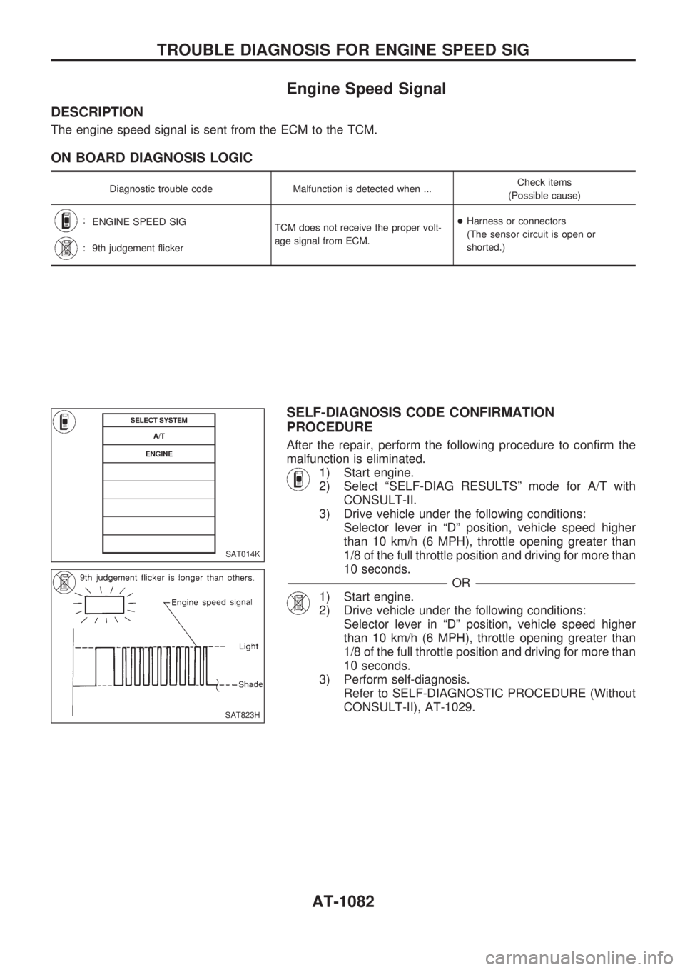
Engine Speed Signal
DESCRIPTION
The engine speed signal is sent from the ECM to the TCM.
ON BOARD DIAGNOSIS LOGIC
Diagnostic trouble code Malfunction is detected when ...Check items
(Possible cause)
:
ENGINE SPEED SIG
TCM does not receive the proper volt-
age signal from ECM.+Harness or connectors
(The sensor circuit is open or
shorted.)
:
9th judgement flicker
SELF-DIAGNOSIS CODE CONFIRMATION
PROCEDURE
After the repair, perform the following procedure to confirm the
malfunction is eliminated.
1) Start engine.
2) Select ªSELF-DIAG RESULTSº mode for A/T with
CONSULT-II.
3) Drive vehicle under the following conditions:
Selector lever in ªDº position, vehicle speed higher
than 10 km/h (6 MPH), throttle opening greater than
1/8 of the full throttle position and driving for more than
10 seconds.
-------------------------------------------------------------------------------------------------------------------------------------------------------------------------------------------------------------------------------------------------OR-------------------------------------------------------------------------------------------------------------------------------------------------------------------------------------------------------------------------------------------------
1) Start engine.
2) Drive vehicle under the following conditions:
Selector lever in ªDº position, vehicle speed higher
than 10 km/h (6 MPH), throttle opening greater than
1/8 of the full throttle position and driving for more than
10 seconds.
3) Perform self-diagnosis.
Refer to SELF-DIAGNOSTIC PROCEDURE (Without
CONSULT-II), AT-1029.
SAT014K
SAT823H
TROUBLE DIAGNOSIS FOR ENGINE SPEED SIG
AT-1082
Page 85 of 1033
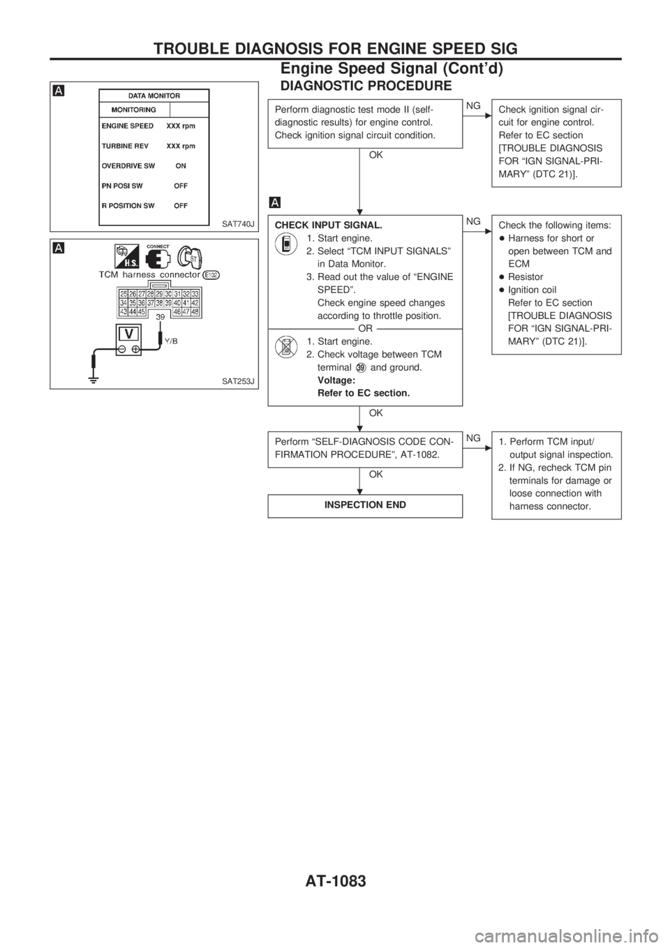
DIAGNOSTIC PROCEDURE
Perform diagnostic test mode II (self-
diagnostic results) for engine control.
Check ignition signal circuit condition.
OK
cNG
Check ignition signal cir-
cuit for engine control.
Refer to EC section
[TROUBLE DIAGNOSIS
FOR ªIGN SIGNAL-PRI-
MARYº (DTC 21)].
CHECK INPUT SIGNAL.
1. Start engine.
2. Select ªTCM INPUT SIGNALSº
in Data Monitor.
3. Read out the value of ªENGINE
SPEEDº.
Check engine speed changes
according to throttle position.
------------------------------------------------------------------------------------------------------------------------------------OR------------------------------------------------------------------------------------------------------------------------------------
1. Start engine.
2. Check voltage between TCM
terminal
V39and ground.
Voltage:
Refer to EC section.
OK
cNG
Check the following items:
+Harness for short or
open between TCM and
ECM
+Resistor
+Ignition coil
Refer to EC section
[TROUBLE DIAGNOSIS
FOR ªIGN SIGNAL-PRI-
MARYº (DTC 21)].
Perform ªSELF-DIAGNOSIS CODE CON-
FIRMATION PROCEDUREº, AT-1082.
OK
cNG
1. Perform TCM input/
output signal inspection.
2. If NG, recheck TCM pin
terminals for damage or
loose connection with
harness connector.
INSPECTION END
SAT740J
SAT253J
.
.
.
TROUBLE DIAGNOSIS FOR ENGINE SPEED SIG
Engine Speed Signal (Cont'd)
AT-1083
Page 234 of 1033
ENGINE CONTROL SYSTEM
SECTION
EC
MODIFICATION NOTICE:
+The RD28ETi engine has been replaced by the ZD30DDTi engine.
CONTENTS
ZD30DDTi
PRECAUTIONS AND PREPARATION............... 1005
Special Service Tool ........................................ 1005
Supplemental Restraint System (SRS) ªAIR
BAGº and ªSEAT BELT PRE-TENSIONERº ... 1005
TROUBLE DIAGNOSIS Ð INDEX...................... 1006
Alphabetical & Numerical Index for DTC......... 1006
PRECAUTIONS................................................... 1008
Precautions ...................................................... 1008
ENGINE AND EMISSION CONTROL OVERALL
SYSTEM............................................................... 1011
ECCS-D Component Parts Location ............... 1011
Circuit Diagram ................................................ 1015
System Diagram .............................................. 1016
Vacuum Hose Drawing .................................... 1017
System Chart ................................................... 1018
ENGINE AND EMISSION BASIC CONTROL
SYSTEM............................................................... 1019
Fuel Injection Control System.......................... 1019
Fuel Injection Timing Control System.............. 1021
Air Conditioning Cut Control ............................ 1021
Fuel Cut Control (at no load & high engine
speed) .............................................................. 1021
Crankcase Ventilation System ......................... 1022
BASIC SERVICE PROCEDURE......................... 1023
Injection Tube and Injection Nozzle ................ 1023
Electronic Control Fuel Injection Pump ........... 1026
Air Bleeding...................................................... 1031
ON BOARD DIAGNOSTIC SYSTEM
DESCRIPTION..................................................... 1032
DTC and MI Detection Logic ........................... 1032
Diagnostic Trouble Code (DTC) ...................... 1032
Malfunction Indicator (MI) ................................ 1033CONSULT-II ..................................................... 1038
TROUBLE DIAGNOSIS Ð INTRODUCTION..... 1045
Introduction ...................................................... 1045
Work Flow ........................................................ 1047
TROUBLE DIAGNOSIS Ð BASIC
INSPECTION........................................................ 1049
Basic Inspection ............................................... 1049
TROUBLE DIAGNOSIS Ð GENERAL
DESCRIPTION..................................................... 1055
Symptom Matrix Chart ..................................... 1055
CONSULT-II Reference Value in Data Monitor
Mode ................................................................ 1065
Major Sensor Reference Graph in Data
Monitor Mode ................................................... 1067
ECM Terminals and Reference Value ............. 1068
TROUBLE DIAGNOSIS FOR INTERMITTENT
INCIDENT............................................................. 1076
Description ....................................................... 1076
Diagnostic Procedure....................................... 1076
TROUBLE DIAGNOSIS FOR POWER
SUPPLY............................................................... 1077
Main Power Supply and Ground Circuit .......... 1077
DTC 0102 MASS AIR FLOW SEN...................... 1086
Component Description ................................... 1086
CONSULT-II Reference Value in Data Monitor
Mode ................................................................ 1086
ECM Terminals and Reference Value ............. 1086
On Board Diagnosis Logic ............................... 1086
DTC Confirmation Procedure .......................... 1087
Wiring Diagram ................................................ 1088
Diagnostic Procedure....................................... 1089
DTC 0103 COOLANT TEMP SEN...................... 1092
Description ....................................................... 1092
EC