2000 NISSAN PATROL Check engine light
[x] Cancel search: Check engine lightPage 4 of 1033

Diagnostic Procedure....................................... 1088
TROUBLE DIAGNOSIS FOR CONTROL UNIT
(EFP ROM)........................................................... 1089
Description ....................................................... 1089
Diagnostic Procedure....................................... 1090
TROUBLE DIAGNOSIS FOR
NON-DETECTABLE ITEMS................................ 1091
PNP, Overdrive Control, A/T Mode or
Accelerator Position Switches ......................... 1091
DIAGNOSTIC PROCEDURES FOR
SYMPTOMS......................................................... 1097
1. SPORT Indicator Lamp Does Not
Come On.......................................................... 1097
2. SPORT Indicator Lamp Does Not
Come On.......................................................... 1098
3. O/D OFF Indicator Lamp Does Not Come
On .................................................................... 1098
4. SPORT Indicator Lamp Does Not
Come On.......................................................... 1099
5. Engine Cannot Be Started In ªPº and ªNº
Position ............................................................ 1100
6. In ªPº Position, Vehicle Moves Forward Or
Backward When Pushed ................................. 1100
7. In ªNº Position, Vehicle Moves .................... 1101
8. Large Shock. ªNº®ªRº Position ................ 1102
9. Vehicle Does Not Creep Backward In ªRº
Position ............................................................ 1103
10. Vehicle Does Not Creep Forward In ªDº,
ª2º Or ª1º Position ............................................ 1104
11. Vehicle Cannot Be Started From D
1......... 1105
12. A/T Does Not Shift: D
1®D2Or Does Not
Kickdown: D
4®D2......................................... 1106
13. A/T Does Not Shift: D
2®D3.................... 1107
14. A/T Does Not Shift: D
3®D4.................... 1108
15. A/T Does Not Perform Lock-up ................. 1109
16. A/T Does Not Hold Lock-up Condition ...... 1110
17. Lock-up Is Not Released ........................... 1110
18. Engine Speed Does Not Return To Idle
(Light Braking D
4®D3) .................................. 1111
19. Vehicle Does Not Start From D
1............... 1112
20. A/T Does Not Shift: D
2®D1When
Depressing Accelerator Pedal ......................... 1113
21. A/T Does Not Shift: D
4®D3, When
Overdrive Control Switch ªONº®ªOFFº ........ 1114
22. A/T Does Not Shift: D
3®22, When
Selector Lever ªDº®ª2º Position ................... 1114
23. A/T Does Not Shift: 2
2®11, WhenSelector Lever ª2º®ª1º Position .................... 1115
24. Vehicle Does Not Decelerate By Engine
Brake ................................................................ 1115
TROUBLE DIAGNOSES Ð A/T Shift Lock
System................................................................. 1116
Description ....................................................... 1116
Wiring Diagram Ð SHIFT Ð ........................... 1117
Diagnostic Procedure....................................... 1118
Key Interlock Cable.......................................... 1121
Component Check ........................................... 1122
ON-VEHICLE SERVICE...................................... 1124
Control Valve Assembly and Accumulators .... 1124
Revolution Sensor Replacement ..................... 1125
Rear Oil Seal Replacement ............................. 1125
Parking Pawl Components Inspection ............. 1125
PNP Switch Adjustment ................................... 1125
Manual Control Linkage Adjustment................ 1126
REMOVAL AND INSTALLATION....................... 1127
Removal ........................................................... 1127
Installation ........................................................ 1128
MAJOR OVERHAUL........................................... 1129
Oil Channel ...................................................... 1131
Locations of Needle Bearings, Thrust Washers
and Snap Rings ............................................... 1132
DISASSEMBLY.................................................... 1133
REPAIR FOR COMPONENT PARTS................. 1144
Oil Pump .......................................................... 1144
Control Valve Assembly................................... 1148
Control Valve Upper Body ............................... 1154
Control Valve Lower Body ............................... 1159
Reverse Clutch ................................................ 1161
High Clutch ...................................................... 1165
Forward and Overrun Clutches ....................... 1167
Low & Reverse Brake ...................................... 1171
Forward Clutch Drum Assembly ...................... 1175
Rear Internal Gear and Forward Clutch Hub .. 1177
Band Servo Piston Assembly .......................... 1180
Parking Pawl Components .............................. 1184
ASSEMBLY.......................................................... 1186
Assembly (1) .................................................... 1186
Adjustment ....................................................... 1190
Assembly (2) .................................................... 1195
A/T FLUID COOLER SYSTEM........................... 1205
A/T Fluid Cooler ............................................... 1205
SERVICE DATA AND SPECIFICATIONS (SDS)1206
General Specifications ..................................... 1206
Specifications and Adjustment......................... 1206
When you read wiring diagrams:
+Read GI section, ªHOW TO READ WIRING DIAGRAMSº.
+See EL section, ªPOWER SUPPLY ROUTINGº for power distribution circuit.
When you perform trouble diagnoses, read GI section, ªHOW TO FOLLOW FLOW
CHART IN TROUBLE DIAGNOSESº.
AT-1002
Page 36 of 1033
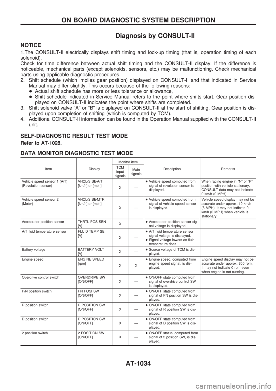
Diagnosis by CONSULT-II
NOTICE
1.The CONSULT-II electrically displays shift timing and lock-up timing (that is, operation timing of each
solenoid).
Check for time difference between actual shift timing and the CONSULT-II display. If the difference is
noticeable, mechanical parts (except solenoids, sensors, etc.) may be malfunctioning. Check mechanical
parts using applicable diagnostic procedures.
2. Shift schedule (which implies gear position) displayed on CONSULT-II and that indicated in Service
Manual may differ slightly. This occurs because of the following reasons:
+Actual shift schedule has more or less tolerance or allowance,
+Shift schedule indicated in Service Manual refers to the point where shifts start. Gear position dis-
played on CONSULT-II indicates the point where shifts are completed.
3. Shift solenoid valve ªAº or ªBº is displayed on CONSULT-II at the start of shifting. Gear position is dis-
played upon completion of shifting (which is computed by TCM).
4. Additional CONSULT-II information can be found in the Operation Manual supplied with the CONSULT-II
unit.
SELF-DIAGNOSTIC RESULT TEST MODE
Refer to AT-1028.
DATA MONITOR DIAGNOSTIC TEST MODE
Item DisplayMonitor item
Description Remarks TCM
input
signalsMain
signals
Vehicle speed sensor 1 (A/T)
(Revolution sensor)VHCL/S SEzA/T
[km/h] or [mph]
XÐ+Vehicle speed computed from
signal of revolution sensor is
displayed.When racing engine in ªNº or ªPº
position with vehicle stationary,
CONSULT data may not indicate
0 km/h (0 MPH).
Vehicle speed sensor 2
(Meter)VHCL/S SEzMTR
[km/h] or [mph]
XÐ+Vehicle speed computed from
signal of vehicle speed sensor
is displayed.Vehicle speed display may not be
accurate under approx. 10 km/h
(6 MPH). It may not indicate 0
km/h (0 MPH) when vehicle is
stationary.
Accelerator position sensor THRTL POS SEN
[V]XÐ+Accelerator position sensor sig-
nal voltage is displayed.
A/T fluid temperature sensor FLUID TEMP SE
[V]
XÐ+A/T fluid temperature sensor
signal voltage is displayed.
+Signal voltage lowers as fluid
temperature rises.
Battery voltage BATTERY VOLT
[V]XÐ+Source voltage of TCM is dis-
played.
Engine speed ENGINE SPEED
[rpm]
XX+Engine speed, computed from
engine speed signal, is dis-
played.Engine speed display may not be
accurate under approx. 800 rpm.
It may not indicate 0 rpm even
when engine is not running.
Overdrive control switch OVERDRIVE SW
[ON/OFF] X Ð+ON/OFF state computed from
signal of overdrive control SW
is displayed.
P/N position switch PN POSI SW
[ON/OFF] X Ð+ON/OFF state computed from
signal of PN position SW is dis-
played.
R position switch R POSITION SW
[ON/OFF] X Ð+ON/OFF state computed from
signal of R position SW is dis-
played.
D position switch D POSITION SW
[ON/OFF] X Ð+ON/OFF state computed from
signal of D position SW is dis-
played.
2 position switch 2 POSITION SW
[ON/OFF] X Ð+ON/OFF status, computed from
signal of 2 position SW, is dis-
played.
ON BOARD DIAGNOSTIC SYSTEM DESCRIPTION
AT-1034
Page 40 of 1033
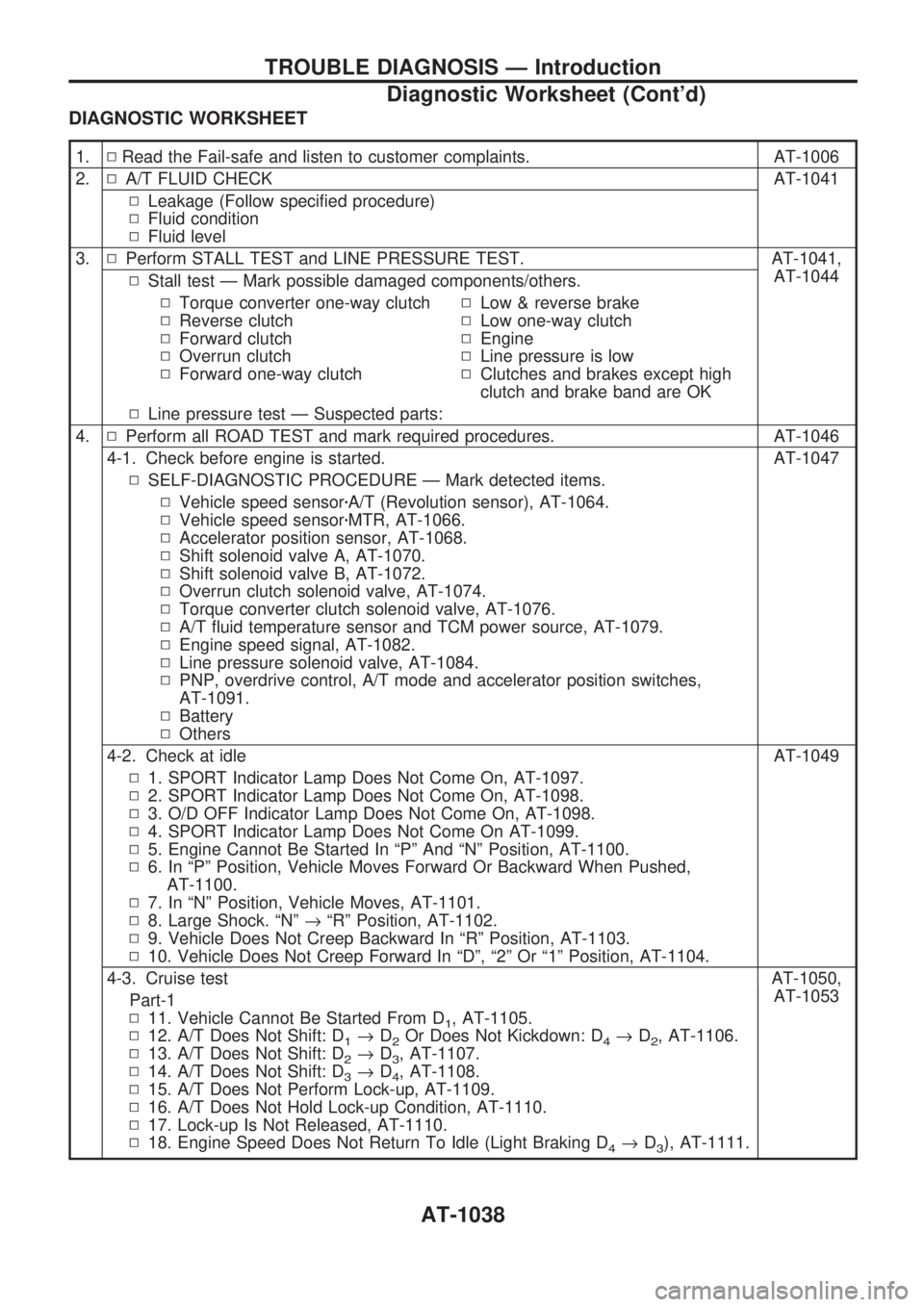
DIAGNOSTIC WORKSHEET
1.NRead the Fail-safe and listen to customer complaints. AT-1006
2.NA/T FLUID CHECK AT-1041
NLeakage (Follow specified procedure)
NFluid condition
NFluid level
3.NPerform STALL TEST and LINE PRESSURE TEST. AT-1041,
AT-1044
NStall test Ð Mark possible damaged components/others.
NTorque converter one-way clutch
NReverse clutch
NForward clutch
NOverrun clutch
NForward one-way clutchNLow & reverse brake
NLow one-way clutch
NEngine
NLine pressure is low
NClutches and brakes except high
clutch and brake band are OK
NLine pressure test Ð Suspected parts:
4.NPerform all ROAD TEST and mark required procedures. AT-1046
4-1. Check before engine is started. AT-1047
NSELF-DIAGNOSTIC PROCEDURE Ð Mark detected items.
NVehicle speed sensorzA/T (Revolution sensor), AT-1064.
NVehicle speed sensorzMTR, AT-1066.
NAccelerator position sensor, AT-1068.
NShift solenoid valve A, AT-1070.
NShift solenoid valve B, AT-1072.
NOverrun clutch solenoid valve, AT-1074.
NTorque converter clutch solenoid valve, AT-1076.
NA/T fluid temperature sensor and TCM power source, AT-1079.
NEngine speed signal, AT-1082.
NLine pressure solenoid valve, AT-1084.
NPNP, overdrive control, A/T mode and accelerator position switches,
AT-1091.
NBattery
NOthers
4-2. Check at idle AT-1049
N1. SPORT Indicator Lamp Does Not Come On, AT-1097.
N2. SPORT Indicator Lamp Does Not Come On, AT-1098.
N3. O/D OFF Indicator Lamp Does Not Come On, AT-1098.
N4. SPORT Indicator Lamp Does Not Come On AT-1099.
N5. Engine Cannot Be Started In ªPº And ªNº Position, AT-1100.
N6. In ªPº Position, Vehicle Moves Forward Or Backward When Pushed,
AT-1100.
N7. In ªNº Position, Vehicle Moves, AT-1101.
N8. Large Shock. ªNº®ªRº Position, AT-1102.
N9. Vehicle Does Not Creep Backward In ªRº Position, AT-1103.
N10. Vehicle Does Not Creep Forward In ªDº, ª2º Or ª1º Position, AT-1104.
4-3. Cruise test AT-1050,
AT-1053
Part-1
N11. Vehicle Cannot Be Started From D
1, AT-1105.
N12. A/T Does Not Shift: D
1®D2Or Does Not Kickdown: D4®D2, AT-1106.
N13. A/T Does Not Shift: D
2®D3, AT-1107.
N14. A/T Does Not Shift: D
3®D4, AT-1108.
N15. A/T Does Not Perform Lock-up, AT-1109.
N16. A/T Does Not Hold Lock-up Condition, AT-1110.
N17. Lock-up Is Not Released, AT-1110.
N18. Engine Speed Does Not Return To Idle (Light Braking D
4®D3), AT-1111.
TROUBLE DIAGNOSIS Ð Introduction
Diagnostic Worksheet (Cont'd)
AT-1038
Page 43 of 1033
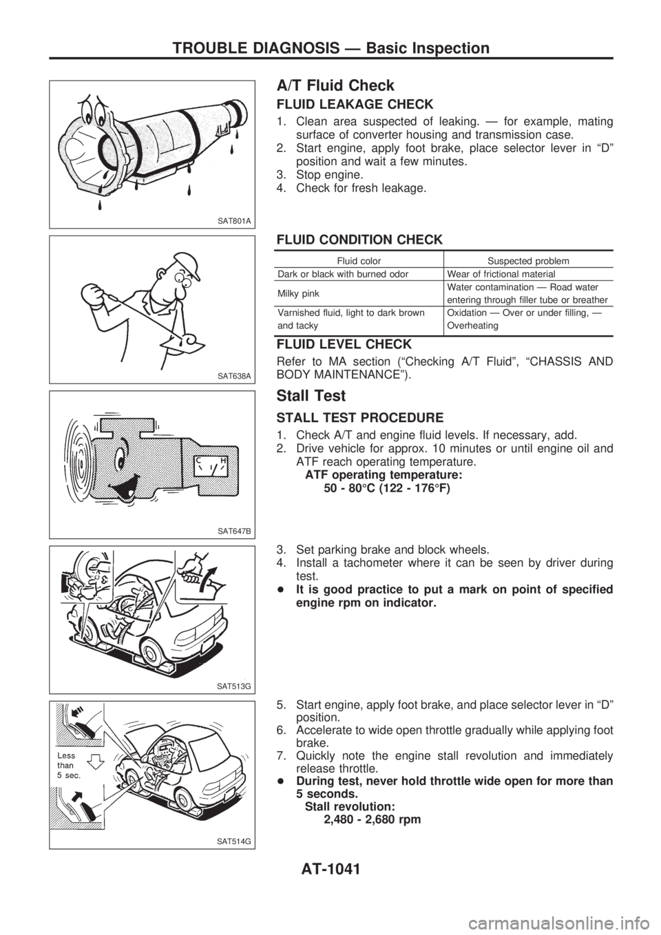
A/T Fluid Check
FLUID LEAKAGE CHECK
1. Clean area suspected of leaking. Ð for example, mating
surface of converter housing and transmission case.
2. Start engine, apply foot brake, place selector lever in ªDº
position and wait a few minutes.
3. Stop engine.
4. Check for fresh leakage.
FLUID CONDITION CHECK
Fluid color Suspected problem
Dark or black with burned odor Wear of frictional material
Milky pinkWater contamination Ð Road water
entering through filler tube or breather
Varnished fluid, light to dark brown
and tackyOxidation Ð Over or under filling, Ð
Overheating
FLUID LEVEL CHECK
Refer to MA section (ªChecking A/T Fluidº, ªCHASSIS AND
BODY MAINTENANCEº).
Stall Test
STALL TEST PROCEDURE
1. Check A/T and engine fluid levels. If necessary, add.
2. Drive vehicle for approx. 10 minutes or until engine oil and
ATF reach operating temperature.
ATF operating temperature:
50 - 80ÉC (122 - 176ÉF)
3. Set parking brake and block wheels.
4. Install a tachometer where it can be seen by driver during
test.
+It is good practice to put a mark on point of specified
engine rpm on indicator.
5. Start engine, apply foot brake, and place selector lever in ªDº
position.
6. Accelerate to wide open throttle gradually while applying foot
brake.
7. Quickly note the engine stall revolution and immediately
release throttle.
+During test, never hold throttle wide open for more than
5 seconds.
Stall revolution:
2,480 - 2,680 rpm
SAT801A
SAT638A
SAT647B
SAT513G
SAT514G
TROUBLE DIAGNOSIS Ð Basic Inspection
AT-1041
Page 113 of 1033
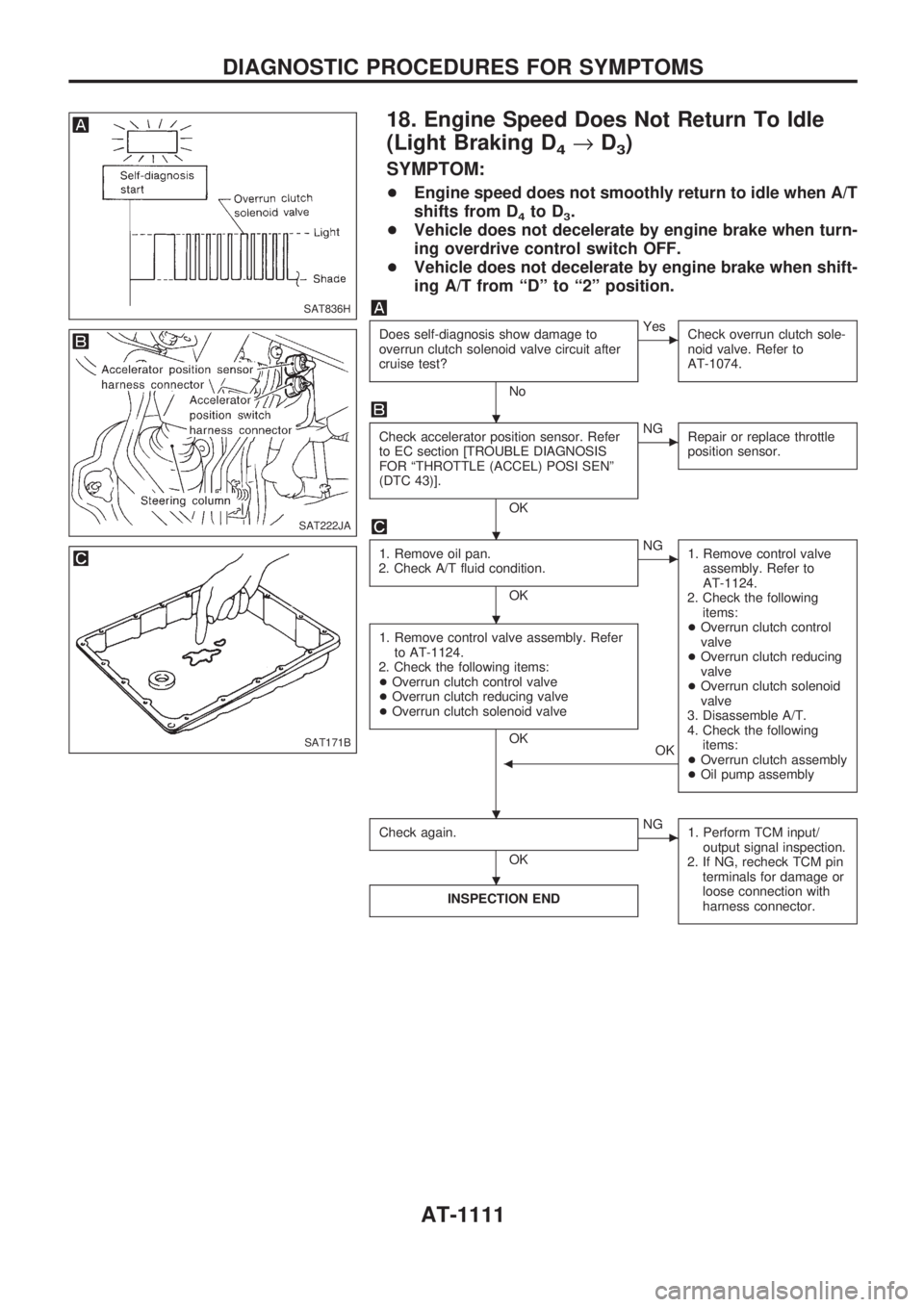
18. Engine Speed Does Not Return To Idle
(Light Braking D
4®D3)
SYMPTOM:
+Engine speed does not smoothly return to idle when A/T
shifts from D
4to D3.
+Vehicle does not decelerate by engine brake when turn-
ing overdrive control switch OFF.
+Vehicle does not decelerate by engine brake when shift-
ing A/T from ªDº to ª2º position.
Does self-diagnosis show damage to
overrun clutch solenoid valve circuit after
cruise test?
No
cYes
Check overrun clutch sole-
noid valve. Refer to
AT-1074.
Check accelerator position sensor. Refer
to EC section [TROUBLE DIAGNOSIS
FOR ªTHROTTLE (ACCEL) POSI SENº
(DTC 43)].
OK
cNG
Repair or replace throttle
position sensor.
1. Remove oil pan.
2. Check A/T fluid condition.
OK
cNG
1. Remove control valve
assembly. Refer to
AT-1124.
2. Check the following
items:
+Overrun clutch control
valve
+Overrun clutch reducing
valve
+Overrun clutch solenoid
valve
3. Disassemble A/T.
4. Check the following
items:
+Overrun clutch assembly
+Oil pump assembly
1. Remove control valve assembly. Refer
to AT-1124.
2. Check the following items:
+Overrun clutch control valve
+Overrun clutch reducing valve
+Overrun clutch solenoid valve
OK
OK
b
Check again.
OK
cNG
1. Perform TCM input/
output signal inspection.
2. If NG, recheck TCM pin
terminals for damage or
loose connection with
harness connector.
INSPECTION END
SAT836H
SAT222JA
SAT171B
.
.
.
. .
.
DIAGNOSTIC PROCEDURES FOR SYMPTOMS
AT-1111
Page 117 of 1033
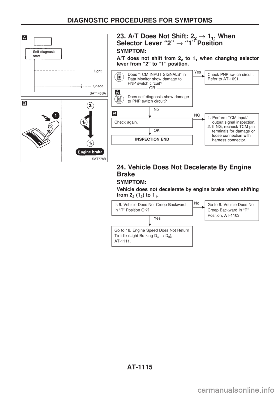
23. A/T Does Not Shift: 22®11, When
Selector Lever ª2º®ª1º Position
SYMPTOM:
A/T does not shift from 22to 11when changing selector
lever from ª2º to ª1º position.
Does ªTCM INPUT SIGNALSº in
Data Monitor show damage to
PNP switch circuit?
------------------------------------------------------------------------------------------------------------------------------------OR------------------------------------------------------------------------------------------------------------------------------------
Does self-diagnosis show damage
to PNP switch circuit?
No
cYes
Check PNP switch circuit.
Refer to AT-1091.
Check again.
OK
cNG
1. Perform TCM input/
output signal inspection.
2. If NG, recheck TCM pin
terminals for damage or
loose connection with
harness connector.
INSPECTION END
24. Vehicle Does Not Decelerate By Engine
Brake
SYMPTOM:
Vehicle does not decelerate by engine brake when shifting
from 2
2(12)to11.
Is 9. Vehicle Does Not Creep Backward
In ªRº Position OK?
Yes
cNo
Go to 9. Vehicle Does Not
Creep Backward In ªRº
Position, AT-1103.
Go to 18. Engine Speed Does Not Return
To Idle (Light Braking D
4®D3),
AT-1111.
SAT146BA
SAT778B
.
.
.
DIAGNOSTIC PROCEDURES FOR SYMPTOMS
AT-1115
Page 130 of 1033
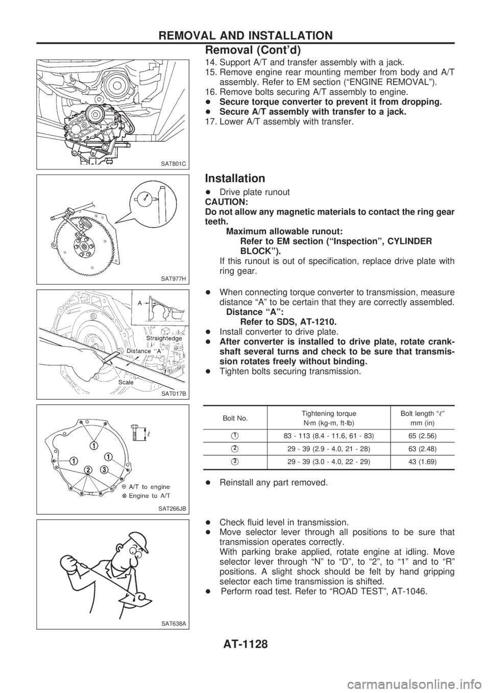
14. Support A/T and transfer assembly with a jack.
15. Remove engine rear mounting member from body and A/T
assembly. Refer to EM section (ªENGINE REMOVALº).
16. Remove bolts securing A/T assembly to engine.
+Secure torque converter to prevent it from dropping.
+Secure A/T assembly with transfer to a jack.
17. Lower A/T assembly with transfer.
Installation
+Drive plate runout
CAUTION:
Do not allow any magnetic materials to contact the ring gear
teeth.
Maximum allowable runout:
Refer to EM section (ªInspectionº, CYLINDER
BLOCKº).
If this runout is out of specification, replace drive plate with
ring gear.
+When connecting torque converter to transmission, measure
distance ªAº to be certain that they are correctly assembled.
Distance ªAº:
Refer to SDS, AT-1210.
+Install converter to drive plate.
+After converter is installed to drive plate, rotate crank-
shaft several turns and check to be sure that transmis-
sion rotates freely without binding.
+Tighten bolts securing transmission.
Bolt No.Tightening torque
Nzm (kg-m, ft-lb)Bolt length ª!º
mm (in)
V183 - 113 (8.4 - 11.6, 61 - 83) 65 (2.56)
V229 - 39 (2.9 - 4.0, 21 - 28) 63 (2.48)
V329 - 39 (3.0 - 4.0, 22 - 29) 43 (1.69)
+Reinstall any part removed.
+Check fluid level in transmission.
+Move selector lever through all positions to be sure that
transmission operates correctly.
With parking brake applied, rotate engine at idling. Move
selector lever through ªNº to ªDº, to ª2º, to ª1º and to ªRº
positions. A slight shock should be felt by hand gripping
selector each time transmission is shifted.
+Perform road test. Refer to ªROAD TESTº, AT-1046.
SAT801C
SAT977H
SAT017B
SAT266JB
SAT638A
REMOVAL AND INSTALLATION
Removal (Cont'd)
AT-1128
Page 266 of 1033
2. Change the diagnostic test mode from Mode II to Mode I by using the data link connector. (See
EC-1035.)
The emission related diagnostic information in the ECM can be erased by changing the diagnostic test mode.
+If the battery is disconnected, the emission-related diagnostic information will be lost after
approx. 24 hours.
+Erasing the emission-related diagnostic information using CONSULT-II is easier and quicker than
switching the diagnostic test mode using the data link connector.
NATS (Nissan Anti-Theft System)
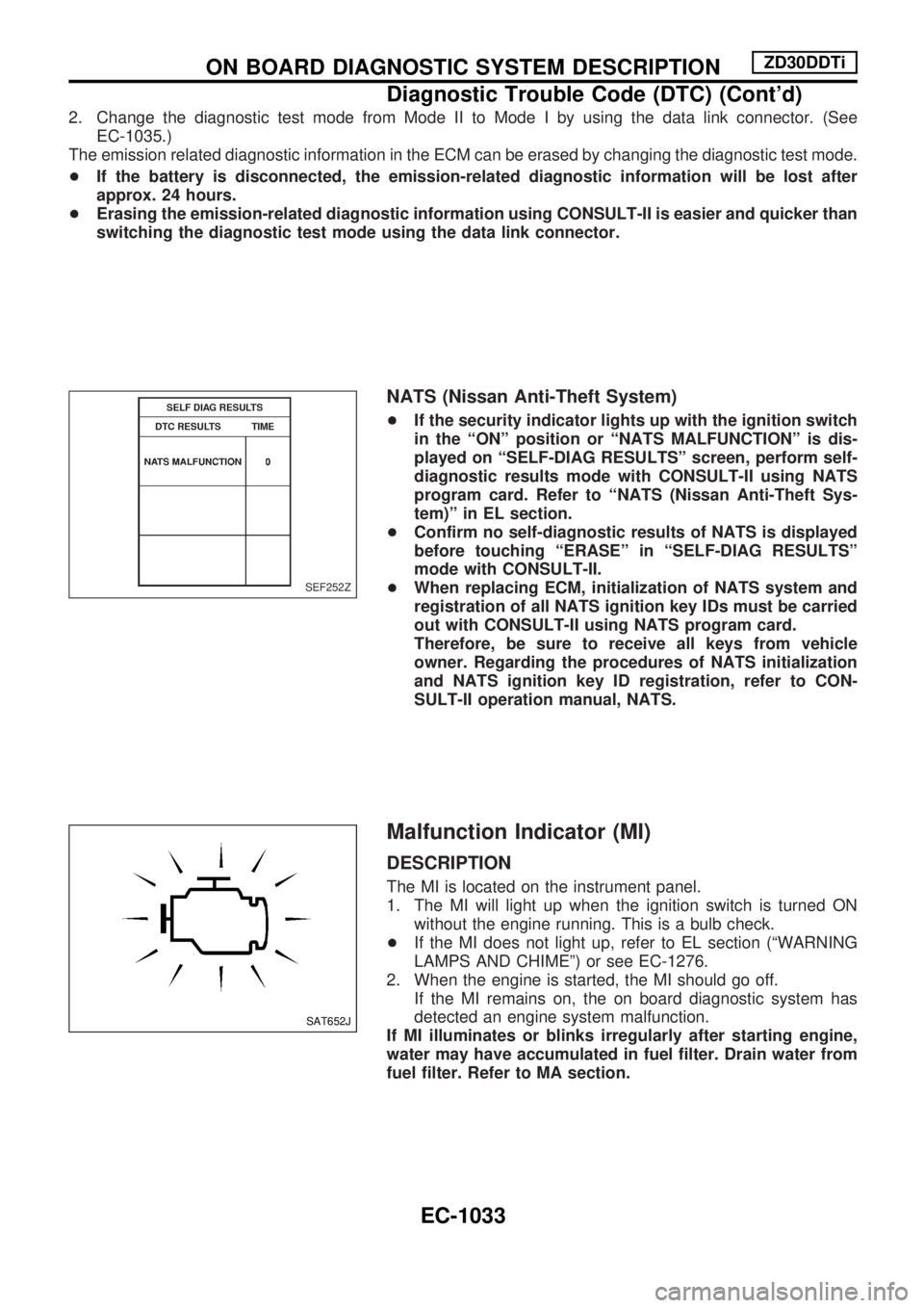
+If the security indicator lights up with the ignition switch
in the ªONº position or ªNATS MALFUNCTIONº is dis-
played on ªSELF-DIAG RESULTSº screen, perform self-
diagnostic results mode with CONSULT-II using NATS
program card. Refer to ªNATS (Nissan Anti-Theft Sys-
tem)º in EL section.
+Confirm no self-diagnostic results of NATS is displayed
before touching ªERASEº in ªSELF-DIAG RESULTSº
mode with CONSULT-II.
+When replacing ECM, initialization of NATS system and
registration of all NATS ignition key IDs must be carried
out with CONSULT-II using NATS program card.
Therefore, be sure to receive all keys from vehicle
owner. Regarding the procedures of NATS initialization
and NATS ignition key ID registration, refer to CON-
SULT-II operation manual, NATS.
Malfunction Indicator (MI)
DESCRIPTION
The MI is located on the instrument panel.
1. The MI will light up when the ignition switch is turned ON
without the engine running. This is a bulb check.
+If the MI does not light up, refer to EL section (ªWARNING
LAMPS AND CHIMEº) or see EC-1276.
2. When the engine is started, the MI should go off.
If the MI remains on, the on board diagnostic system has
detected an engine system malfunction.
If MI illuminates or blinks irregularly after starting engine,
water may have accumulated in fuel filter. Drain water from
fuel filter. Refer to MA section.
SEF252Z
SAT652J
ON BOARD DIAGNOSTIC SYSTEM DESCRIPTIONZD30DDTi
Diagnostic Trouble Code (DTC) (Cont'd)
EC-1033