2000 NISSAN PATROL sensor
[x] Cancel search: sensorPage 153 of 1033
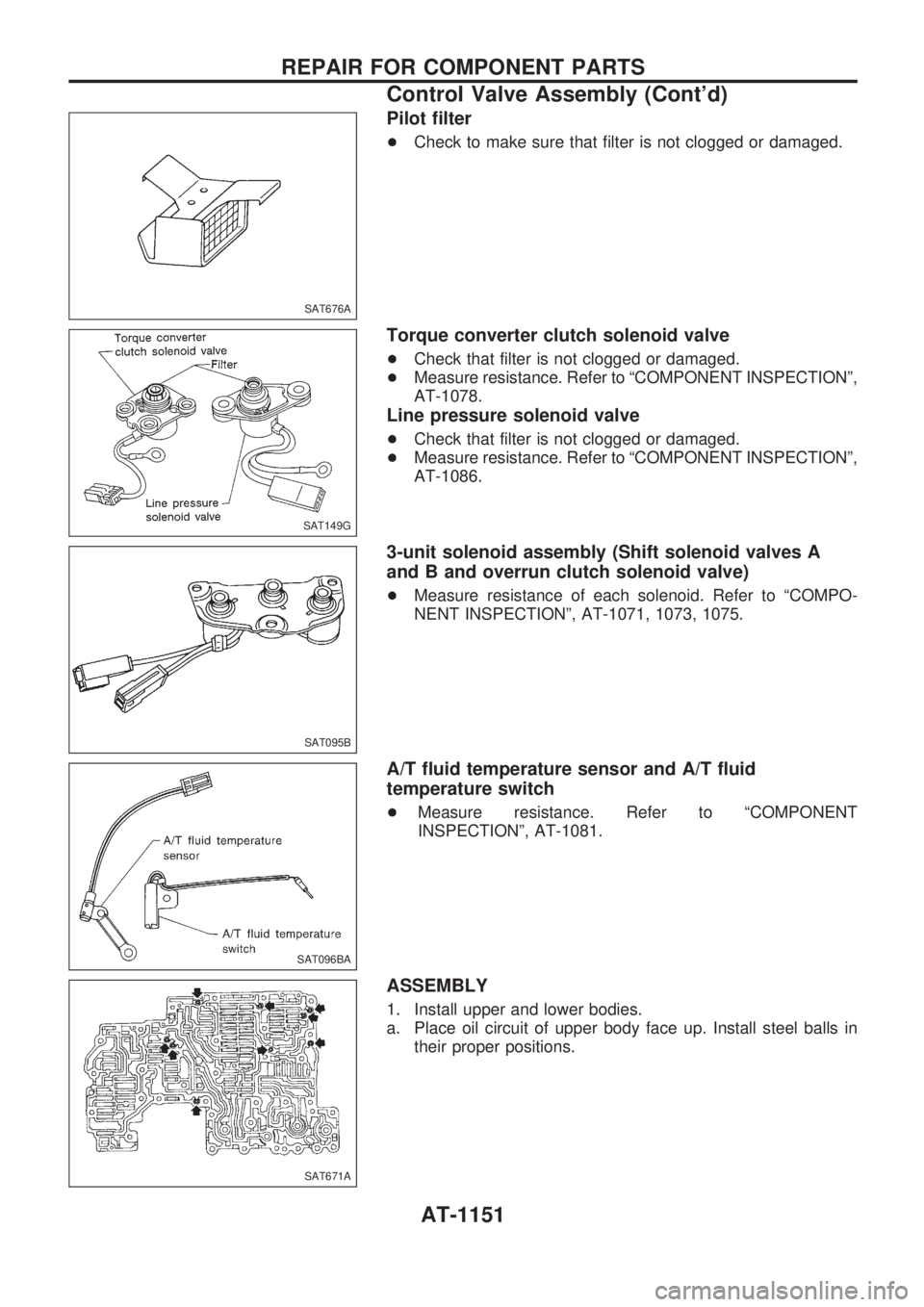
Pilot filter
+Check to make sure that filter is not clogged or damaged.
Torque converter clutch solenoid valve
+Check that filter is not clogged or damaged.
+Measure resistance. Refer to ªCOMPONENT INSPECTIONº,
AT-1078.
Line pressure solenoid valve
+Check that filter is not clogged or damaged.
+Measure resistance. Refer to ªCOMPONENT INSPECTIONº,
AT-1086.
3-unit solenoid assembly (Shift solenoid valves A
and B and overrun clutch solenoid valve)
+Measure resistance of each solenoid. Refer to ªCOMPO-
NENT INSPECTIONº, AT-1071, 1073, 1075.
A/T fluid temperature sensor and A/T fluid
temperature switch
+Measure resistance. Refer to ªCOMPONENT
INSPECTIONº, AT-1081.
ASSEMBLY
1. Install upper and lower bodies.
a. Place oil circuit of upper body face up. Install steel balls in
their proper positions.
SAT676A
SAT149G
SAT095B
SAT096BA
SAT671A
REPAIR FOR COMPONENT PARTS
Control Valve Assembly (Cont'd)
AT-1151
Page 154 of 1033
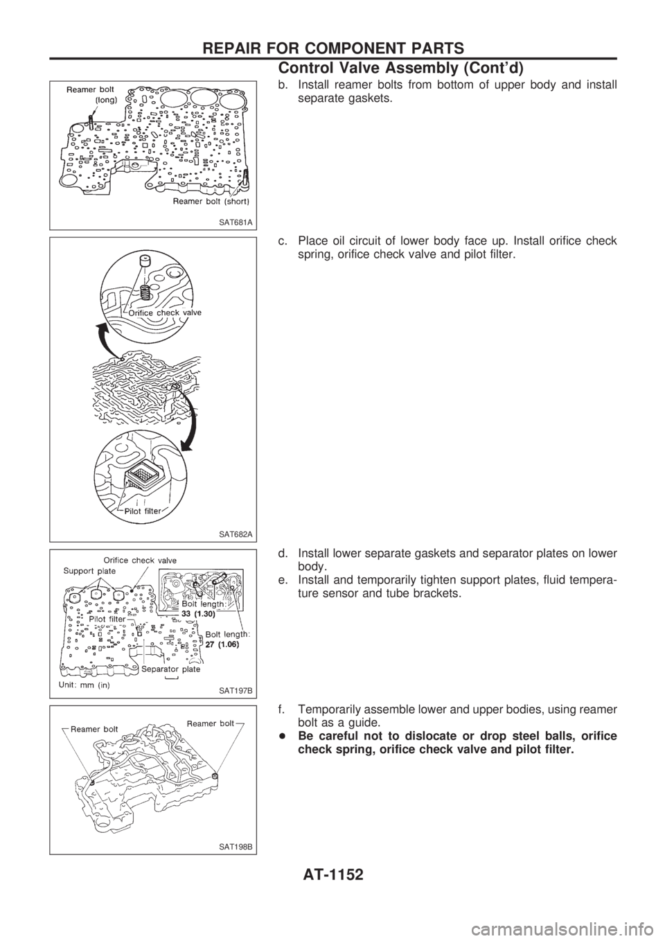
b. Install reamer bolts from bottom of upper body and install
separate gaskets.
c. Place oil circuit of lower body face up. Install orifice check
spring, orifice check valve and pilot filter.
d. Install lower separate gaskets and separator plates on lower
body.
e. Install and temporarily tighten support plates, fluid tempera-
ture sensor and tube brackets.
f. Temporarily assemble lower and upper bodies, using reamer
bolt as a guide.
+Be careful not to dislocate or drop steel balls, orifice
check spring, orifice check valve and pilot filter.
SAT681A
SAT682A
SAT197B
SAT198B
REPAIR FOR COMPONENT PARTS
Control Valve Assembly (Cont'd)
AT-1152
Page 198 of 1033
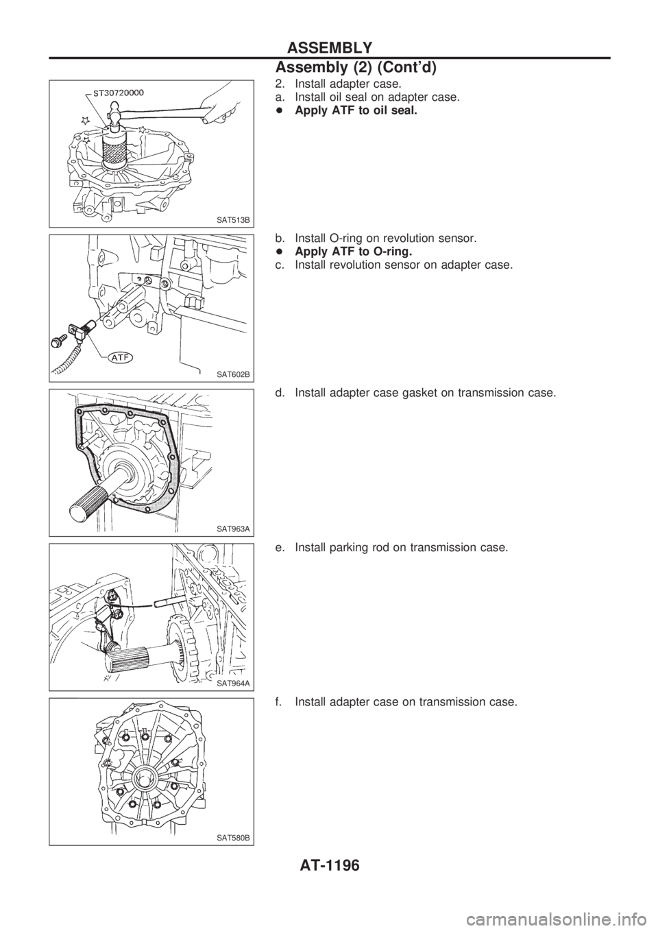
2. Install adapter case.
a. Install oil seal on adapter case.
+Apply ATF to oil seal.
b. Install O-ring on revolution sensor.
+Apply ATF to O-ring.
c. Install revolution sensor on adapter case.
d. Install adapter case gasket on transmission case.
e. Install parking rod on transmission case.
f. Install adapter case on transmission case.
SAT513B
SAT602B
SAT963A
SAT964A
SAT580B
ASSEMBLY
Assembly (2) (Cont'd)
AT-1196
Page 204 of 1033
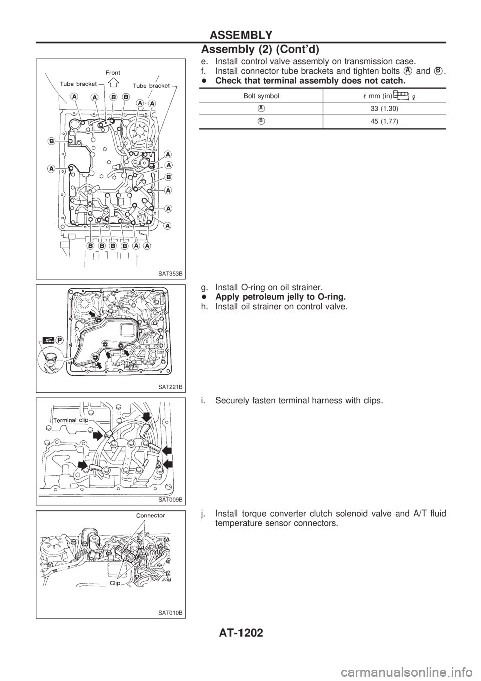
e. Install control valve assembly on transmission case.
f. Install connector tube brackets and tighten bolts
VAandVB.
+Check that terminal assembly does not catch.
Bolt symbol!mm (in)
VA33 (1.30)
VB45 (1.77)
g. Install O-ring on oil strainer.
+Apply petroleum jelly to O-ring.
h. Install oil strainer on control valve.
i. Securely fasten terminal harness with clips.
j. Install torque converter clutch solenoid valve and A/T fluid
temperature sensor connectors.
SAT353B
SAT221B
SAT009B
SAT010B
ASSEMBLY
Assembly (2) (Cont'd)
AT-1202
Page 224 of 1033
Supplemental Restraint System (SRS) ªAIR
BAGº and ªSEAT BELT PRE-TENSIONERº
The Supplemental Restraint System such as ªAIR BAGº and ªSEAT BELT PRE-TENSIONERº used along
with a seat belt, helps to reduce the risk or severity of injury to the driver and front passenger for certain
types of collision. The SRS system composition which is available to NISSAN MODEL Y61 is as follows (The
composition varies according to the destination and optional equipment.):
+For a frontal collision
The Supplemental Restraint System consists of driver air bag module (located in the center of the
steering wheel), front passenger air bag module (located on the instrument panel on passenger side),
seat belt pre-tensioners, a diagnosis sensor unit, warning lamp, wiring harness and spiral cable.
+ For a side collision
The Supplemental Restraint System consists of front side air bag module (located in the outer side of
front seat), satellite sensor, diagnosis sensor unit (one of components of air bags for a frontal collision),
wiring harness, warning lamp (one of components of air bags for a frontal collision).
Information necessary to service the system safely is included in the RS sectionof this Service Manual.
WARNING:
+ To avoid rendering the SRS inoperative, which could increase the risk of personal injury or death
in the event of a collision which would result in air bag inflation, all maintenance should be per-
formed by an authorized NISSAN dealer.
+ Improper maintenance, including incorrect removal and installation of the SRS, can lead to per-
sonal injury caused by intentional activation of the system. For removal of Spiral Cable and Air
Bag Module, see the RS section.
+ Do not use electrical test equipment on any circuit related to the SRS unless instructed to in this
Service Manual. Spiral cable and wiring harnesses covered with yellow insulation tape either just
before the harness connectors or for the complete harness are related to the SRS.
PRECAUTIONS
BT-1002
Page 234 of 1033
ENGINE CONTROL SYSTEM
SECTION
EC
MODIFICATION NOTICE:
+The RD28ETi engine has been replaced by the ZD30DDTi engine.
CONTENTS
ZD30DDTi
PRECAUTIONS AND PREPARATION............... 1005
Special Service Tool ........................................ 1005
Supplemental Restraint System (SRS) ªAIR
BAGº and ªSEAT BELT PRE-TENSIONERº ... 1005
TROUBLE DIAGNOSIS Ð INDEX...................... 1006
Alphabetical & Numerical Index for DTC......... 1006
PRECAUTIONS................................................... 1008
Precautions ...................................................... 1008
ENGINE AND EMISSION CONTROL OVERALL
SYSTEM............................................................... 1011
ECCS-D Component Parts Location ............... 1011
Circuit Diagram ................................................ 1015
System Diagram .............................................. 1016
Vacuum Hose Drawing .................................... 1017
System Chart ................................................... 1018
ENGINE AND EMISSION BASIC CONTROL
SYSTEM............................................................... 1019
Fuel Injection Control System.......................... 1019
Fuel Injection Timing Control System.............. 1021
Air Conditioning Cut Control ............................ 1021
Fuel Cut Control (at no load & high engine
speed) .............................................................. 1021
Crankcase Ventilation System ......................... 1022
BASIC SERVICE PROCEDURE......................... 1023
Injection Tube and Injection Nozzle ................ 1023
Electronic Control Fuel Injection Pump ........... 1026
Air Bleeding...................................................... 1031
ON BOARD DIAGNOSTIC SYSTEM
DESCRIPTION..................................................... 1032
DTC and MI Detection Logic ........................... 1032
Diagnostic Trouble Code (DTC) ...................... 1032
Malfunction Indicator (MI) ................................ 1033CONSULT-II ..................................................... 1038
TROUBLE DIAGNOSIS Ð INTRODUCTION..... 1045
Introduction ...................................................... 1045
Work Flow ........................................................ 1047
TROUBLE DIAGNOSIS Ð BASIC
INSPECTION........................................................ 1049
Basic Inspection ............................................... 1049
TROUBLE DIAGNOSIS Ð GENERAL
DESCRIPTION..................................................... 1055
Symptom Matrix Chart ..................................... 1055
CONSULT-II Reference Value in Data Monitor
Mode ................................................................ 1065
Major Sensor Reference Graph in Data
Monitor Mode ................................................... 1067
ECM Terminals and Reference Value ............. 1068
TROUBLE DIAGNOSIS FOR INTERMITTENT
INCIDENT............................................................. 1076
Description ....................................................... 1076
Diagnostic Procedure....................................... 1076
TROUBLE DIAGNOSIS FOR POWER
SUPPLY............................................................... 1077
Main Power Supply and Ground Circuit .......... 1077
DTC 0102 MASS AIR FLOW SEN...................... 1086
Component Description ................................... 1086
CONSULT-II Reference Value in Data Monitor
Mode ................................................................ 1086
ECM Terminals and Reference Value ............. 1086
On Board Diagnosis Logic ............................... 1086
DTC Confirmation Procedure .......................... 1087
Wiring Diagram ................................................ 1088
Diagnostic Procedure....................................... 1089
DTC 0103 COOLANT TEMP SEN...................... 1092
Description ....................................................... 1092
EC
Page 235 of 1033
On Board Diagnosis Logic ............................... 1092
DTC Confirmation Procedure .......................... 1092
Wiring Diagram ................................................ 1093
Diagnostic Procedure....................................... 1094
DTC 0104 VEHICLE SPEED SEN...................... 1096
Description ....................................................... 1096
ECM Terminals and Reference Value ............. 1096
On Board Diagnosis Logic ............................... 1096
Overall Function Check ................................... 1097
Wiring Diagram ................................................ 1098
Diagnostic Procedure....................................... 1099
DTC 0203 ACCEL POS SW (F/C)...................... 1100
Description ....................................................... 1100
CONSULT-II Reference Value in Data Monitor
Mode ................................................................ 1100
ECM Terminals and Reference Value ............. 1100
On Board Diagnosis Logic ............................... 1100
DTC Confirmation Procedure .......................... 1101
Wiring Diagram ................................................ 1102
Diagnostic Procedure....................................... 1103
DTC 0208 OVER HEAT....................................... 1105
Description ....................................................... 1105
CONSULT-II Reference Value in Data Monitor
Mode ................................................................ 1105
ECM Terminals and Reference Value ............. 1106
On Board Diagnosis Logic ............................... 1106
Overall Function Check ................................... 1107
Wiring Diagram ................................................ 1108
Diagnostic Procedure....................................... 1109
Main 12 Causes of Overheating ...................... 1116
DTC 0301 ECM 2, DTC 0901 ECM 12............... 1117
Description ....................................................... 1117
On Board Diagnosis Logic ............................... 1117
DTC Confirmation Procedure .......................... 1117
Diagnostic Procedure....................................... 1118
DTC 0402 P9zFUEL TEMP SEN......................... 1119
Description ....................................................... 1119
CONSULT-II Reference Value in Data Monitor
Mode ................................................................ 1120
ECM Terminals and Reference Value ............. 1120
On Board Diagnosis Logic ............................... 1120
DTC Confirmation Procedure .......................... 1121
Wiring Diagram ................................................ 1122
Diagnostic Procedure....................................... 1123
DTC 0403 ACCEL POS SENSOR...................... 1125
Description ....................................................... 1125
CONSULT-II Reference Value in Data Monitor
Mode ................................................................ 1125
ECM Terminals and Reference Value ............. 1126
On Board Diagnosis Logic ............................... 1126
DTC Confirmation Procedure .......................... 1127
Wiring Diagram ................................................ 1128
Diagnostic Procedure....................................... 1130
DTC 0406 INT AIR VOL...................................... 1138On Board Diagnosis Logic ............................... 1138
DTC Confirmation Procedure .......................... 1138
Diagnostic Procedure....................................... 1139
DTC 0407 CRANK POS SEN (TDC).................. 1140
Description ....................................................... 1140
CONSULT-II Reference Value in Data Monitor
Mode ................................................................ 1140
ECM Terminals and Reference Value ............. 1140
On Board Diagnosis Logic ............................... 1141
DTC Confirmation Procedure .......................... 1141
Wiring Diagram ................................................ 1142
Diagnostic Procedure....................................... 1143
DTC 0502 BATTERY VOLTAGE........................ 1146
On Board Diagnosis Logic ............................... 1146
DTC Confirmation Procedure .......................... 1146
Diagnostic Procedure....................................... 1146
DTC 0504 A/T COMM LINE................................ 1148
System Description .......................................... 1148
ECM Terminals and Reference Value ............. 1148
On Board Diagnosis Logic ............................... 1148
DTC Confirmation Procedure .......................... 1149
Overall Function Check ................................... 1149
Wiring Diagram ................................................ 1150
Diagnostic Procedure....................................... 1151
DTC 0701 P1zCAM POS SEN............................. 1153
Description ....................................................... 1153
CONSULT-II Reference Value in Data Monitor
Mode ................................................................ 1154
ECM Terminals and Reference Value ............. 1154
On Board Diagnosis Logic ............................... 1154
DTC Confirmation Procedure .......................... 1155
Wiring Diagram ................................................ 1156
Diagnostic Procedure....................................... 1157
DTC 0702 P2zTDC PULSE SIG........................... 1159
Description ....................................................... 1159
CONSULT-II Reference Value in Data Monitor
Mode ................................................................ 1160
ECM Terminals and Reference Value ............. 1160
On Board Diagnosis Logic ............................... 1160
DTC Confirmation Procedure .......................... 1161
Wiring Diagram ................................................ 1162
Diagnostic Procedure....................................... 1163
DTC 0703 P3zPUMP COMM LINE...................... 1165
Description ....................................................... 1165
CONSULT-II Reference Value in Data Monitor
Mode ................................................................ 1166
ECM Terminals and Reference Value ............. 1166
On Board Diagnosis Logic ............................... 1166
DTC Confirmation Procedure .......................... 1167
Wiring Diagram ................................................ 1168
Diagnostic Procedure....................................... 1169
DTC 0704 P4zSPILL/V CIRC, DTC 0706
P6zSPILL VALVE................................................. 1171
Description ....................................................... 1171
EC-1002
Page 237 of 1033
Description ....................................................... 1254
ECM Terminals and Reference Value ............. 1254
Wiring Diagram ................................................ 1255
Diagnostic Procedure....................................... 1256
VARIABLE NOZZLE TURBOCHARGER
CONTROL............................................................ 1261
Description ....................................................... 1261
CONSULT-II Reference Value in Data Monitor
Mode ................................................................ 1261
ECM Terminals and Reference Value ............. 1262
Wiring Diagram ................................................ 1263
Diagnostic Procedure....................................... 1264
EXHAUST GAS CONTROL VALVE CONTROL
SOLENOID........................................................... 1269
Description ....................................................... 1269
CONSULT-II Reference Value in Data Monitor
Mode ................................................................ 1269ECM Terminals and Reference Value ............. 1269
Wiring Diagram ................................................ 1270
Diagnostic Procedure....................................... 1271
AIR CONDITIONER CONTROL.......................... 1275
Wiring Diagram ................................................ 1275
MI & DATA LINK CONNECTORS...................... 1276
Wiring Diagram ................................................ 1276
SERVICE DATA AND SPECIFICATIONS
(SDS).................................................................... 1277
General Specifications ..................................... 1277
Injection Pump Numbers ................................. 1277
Injection Nozzle................................................ 1277
Engine Coolant Temperature Sensor .............. 1277
Crankshaft Position Sensor (TDC) .................. 1277
Glow Plug......................................................... 1277
Accelerator Position Sensor ............................ 1277
EGR Volume Control Valve ............................. 1277
EC-1004