Page 510 of 1033
General Specifications
Unit: rpm
EngineZD30DDTi
Idle speed750 25
Maximum engine speed4,300
Injection Pump Numbers
Engine Part number Pump assembly number
ZD30DDTi 16700 VG100 109342-4023
Injection Nozzle
Unit: kPa (bar, kg/cm2, psi)
Initial injection pressureUsed 19,026 (190.3, 194, 2,759)
New 19,516 - 20,497 (195.2 - 205.0, 199 - 209, 2,830 - 2,972)
Limit 16,182 (161.8, 165, 2,346)
Engine Coolant Temperature Sensor
Temperature ÉC (ÉF) Resistance kW
20 (68) 2.1 - 2.9
50 (122) 0.68 - 1.00
90 (194) 0.236 - 0.260
Crankshaft Position Sensor (TDC)
Resistance [at 20ÉC (68ÉF)]W1,287 - 1,573
Glow Plug
Resistance [at 20ÉC (68ÉF)]WApproximately 0.5
Accelerator Position Sensor
Throttle valve conditions Resistance between terminals 2 and 3 kW[at 25ÉC (77ÉF)]
Completely closedApproximately 0.5
Partially open0.5-4
Completely openApproximately 4
EGR Volume Control Valve
Resistance [at 25ÉC (77ÉF)]W13-17
SERVICE DATA AND SPECIFICATIONS (SDS)ZD30DDTi
EC-1277
Page 737 of 1033

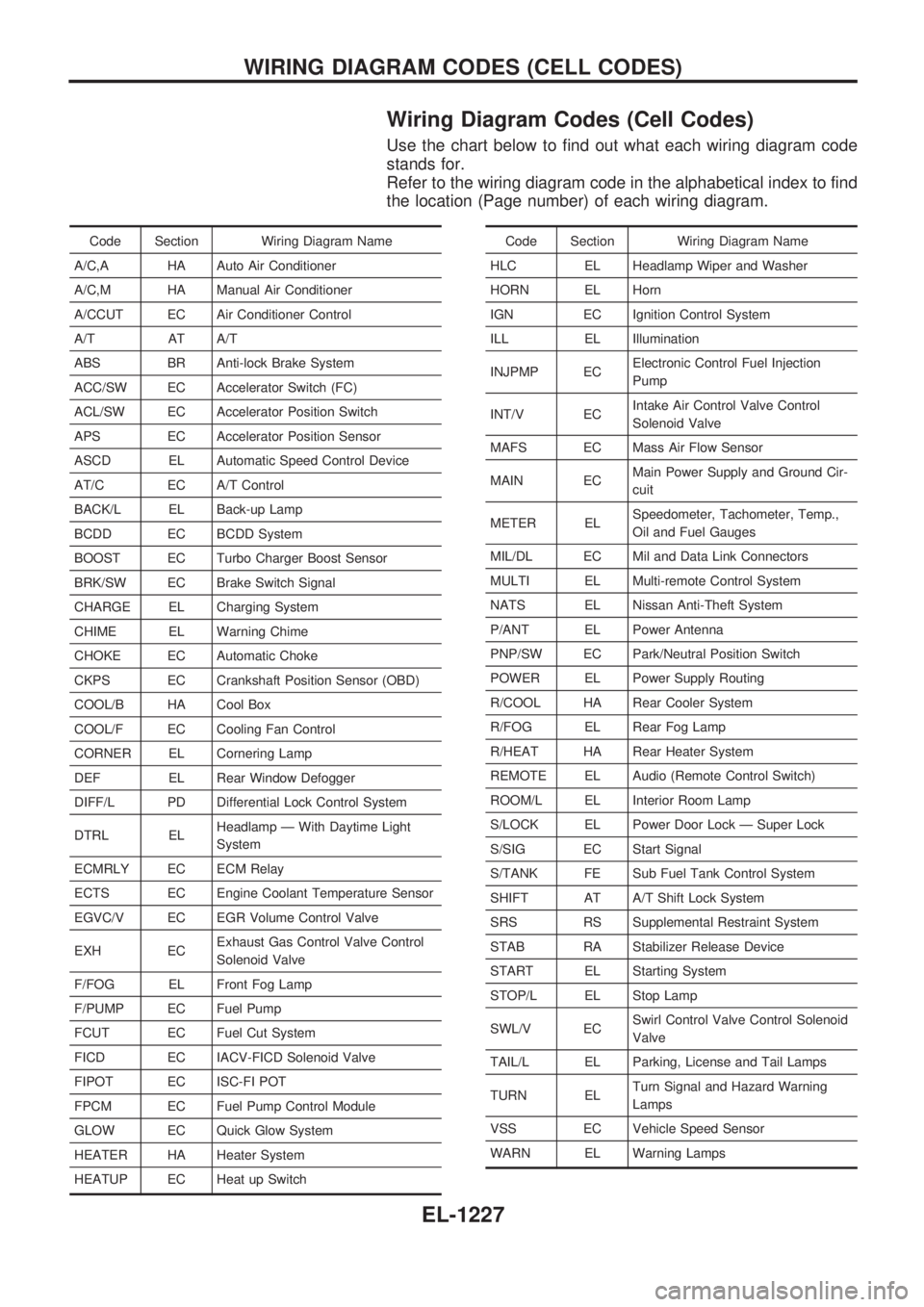
Wiring Diagram Codes (Cell Codes)
Use the chart below to find out what each wiring diagram code
stands for.
Refer to the wiring diagram code in the alphabetical index to find
the location (Page number) of each wiring diagram.
Code Section Wiring Diagram Name
A/C,A HA Auto Air Conditioner
A/C,M HA Manual Air Conditioner
A/CCUT EC Air Conditioner Control
A/T AT A/T
ABS BR Anti-lock Brake System
ACC/SW EC Accelerator Switch (FC)
ACL/SW EC Accelerator Position Switch
APS EC Accelerator Position Sensor
ASCD EL Automatic Speed Control Device
AT/C EC A/T Control
BACK/L EL Back-up Lamp
BCDD EC BCDD System
BOOST EC Turbo Charger Boost Sensor
BRK/SW EC Brake Switch Signal
CHARGE EL Charging System
CHIME EL Warning Chime
CHOKE EC Automatic Choke
CKPS EC Crankshaft Position Sensor (OBD)
COOL/B HA Cool Box
COOL/F EC Cooling Fan Control
CORNER EL Cornering Lamp
DEF EL Rear Window Defogger
DIFF/L PD Differential Lock Control System
DTRL ELHeadlamp Ð With Daytime Light
System
ECMRLY EC ECM Relay
ECTS EC Engine Coolant Temperature Sensor
EGVC/V EC EGR Volume Control Valve
EXH ECExhaust Gas Control Valve Control
Solenoid Valve
F/FOG EL Front Fog Lamp
F/PUMP EC Fuel Pump
FCUT EC Fuel Cut System
FICD EC IACV-FICD Solenoid Valve
FIPOT EC ISC-FI POT
FPCM EC Fuel Pump Control Module
GLOW EC Quick Glow System
HEATER HA Heater System
HEATUP EC Heat up SwitchCode Section Wiring Diagram Name
HLC EL Headlamp Wiper and Washer
HORN EL Horn
IGN EC Ignition Control System
ILL EL Illumination
INJPMP ECElectronic Control Fuel Injection
Pump
INT/V ECIntake Air Control Valve Control
Solenoid Valve
MAFS EC Mass Air Flow Sensor
MAIN ECMain Power Supply and Ground Cir-
cuit
METER ELSpeedometer, Tachometer, Temp.,
Oil and Fuel Gauges
MIL/DL EC Mil and Data Link Connectors
MULTI EL Multi-remote Control System
NATS EL Nissan Anti-Theft System
P/ANT EL Power Antenna
PNP/SW EC Park/Neutral Position Switch
POWER EL Power Supply Routing
R/COOL HA Rear Cooler System
R/FOG EL Rear Fog Lamp
R/HEAT HA Rear Heater System
REMOTE EL Audio (Remote Control Switch)
ROOM/L EL Interior Room Lamp
S/LOCK EL Power Door Lock Ð Super Lock
S/SIG EC Start Signal
S/TANK FE Sub Fuel Tank Control System
SHIFT AT A/T Shift Lock System
SRS RS Supplemental Restraint System
STAB RA Stabilizer Release Device
START EL Starting System
STOP/L EL Stop Lamp
SWL/V ECSwirl Control Valve Control Solenoid
Valve
TAIL/L EL Parking, License and Tail Lamps
TURN ELTurn Signal and Hazard Warning
Lamps
VSS EC Vehicle Speed Sensor
WARN EL Warning Lamps
WIRING DIAGRAM CODES (CELL CODES)
EL-1227
Page 741 of 1033
Parts Requiring Angular Tightening
+Use an angle wrench for the final tightening of the cylinder
head bolts.
+Do not use a torque value for final tightening.
+The torque value for these parts are for a preliminary step.
+Ensure thread and seat surfaces are clean and coated with
engine oil.
Liquid Gasket Application Procedure
1.Use a scraper to remove old liquid gasket from mating
surfaces and grooves. Also, completely clean any oil
from these areas.
2.Apply a continuous bead of liquid gasket to mating sur-
faces. (Use Genuine Liquid Gasket or equivalent.)
+Be sure liquid gasket diameter is as specified.
3.Apply liquid gasket around the inner side of bolt holes
(unless otherwise specified).
4.Assembly should be done within 5 minutes after coating.
5.Wait at least 30 minutes before refilling engine oil and
engine coolant.
SEM164F
AEM080
PRECAUTIONSZD
EM-1003
Page 750 of 1033
Removal and Installation
REMOVAL
1. Remove the following parts.
+Drain engine coolant. Refer to MA section, ªChanging Engine
Coolantº.
+Remove engine cover. Refer to the figure at left.
+Remove intercooler.
+Remove air hose (on throttle body side).
+Remove injection tube.
+Remove or relocate wires/harnesses and tubes/pipes.
SEM292G
INTAKE MANIFOLDZD
EM-1012
Page 752 of 1033
Removal and Installation
REMOVAL
1. Remove the following parts.
+Undercover
+Under guard
+Engine coolant (drain)
Refer to MA section, ªChanging Engine Coolantº.
+Battery (on left side) (for cold areas)
+Exhaust front tube
Refer to FE section, ªRemoval and Installationº, ªEXHAUST
SYSTEMº.
+Remove wires, harnesses, tubes and pipes.
SEM295G
SEM296G
CATALYST AND TURBOCHARGERZD
EM-1014
Page 765 of 1033
Removal and Installation
CAUTION:
As the internal mechanism of the idler gear must first of all,
and always, be set by a bolt when removing the timing chain
before removing the fuel injection pump and timing gear,
follow the procedures on EM-1039, ªRemoval of timing
chain after setting idler gearº, ªElectronic controlled fuel
injection pumpº.
+This chapter will deal with the summary of removing the tim-
ing chain before removing the camshaft and cylinder head.
Removal
1. Remove the following parts.
+Engine cover
+Intercooler
+Air inlet pipe
+Throttle body
+Rocker cover
+Spill tube
+Coolant (Drain)
+Radiator upper hose
+Water outlet
+Radiator shroud
+Cooling fan
+Auxilary belt
FEM003
TIMING CHAINZD
EM-1027
Page 778 of 1033

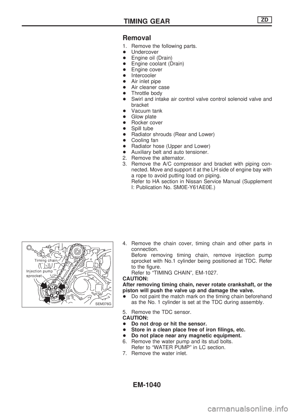
Removal
1. Remove the following parts.
+Undercover
+Engine oil (Drain)
+Engine coolant (Drain)
+Engine cover
+Intercooler
+Air inlet pipe
+Air cleaner case
+Throttle body
+Swirl and intake air control valve control solenoid valve and
bracket
+Vacuum tank
+Glow plate
+Rocker cover
+Spill tube
+Radiator shrouds (Rear and Lower)
+Cooling fan
+Radiator hose (Upper and Lower)
+Auxiliary belt and auto tensioner.
2. Remove the alternator.
3. Remove the A/C compressor and bracket with piping con-
nected. Move and support it at the LH side of engine bay with
a rope to avoid putting load on piping.
Refer to HA section in Nissan Service Manual (Supplement
I: Publication No. SM0E-Y61AE0E.)
4. Remove the chain cover, timing chain and other parts in
connection.
Before removing timing chain, remove injection pump
sprocket with No.1 cylinder being positioned at TDC. Refer
to the figure.
Refer to ªTIMING CHAINº, EM-1027.
CAUTION:
After removing timing chain, never rotate crankshaft, or the
piston will push the valve up and damage the valve.
+Do not paint the match mark on the timing chain beforehand
as the No. 1 cylinder is set at the TDC during assembly.
5. Remove the TDC sensor.
CAUTION:
+Do not drop or hit the sensor.
+Store in a clean place free of iron filings, etc.
+Do not place near any magnetic equipment.
6. Remove the water pump and its stud bolts.
Refer to ªWATER PUMPº in LC section.
7. Remove the water inlet.
SEM376G
TIMING GEARZD
EM-1040
Page 802 of 1033
Precautions
+Do not perform operation unless it is perfectly safe.
+Do not start operation unless the exhaust system and cool-
ant are cooled down.
+Lift the engine at the designated support points only.
+Perform operations for the items other than the engine body,
referring to the applicable sections.
+Refer to MT section and AT section for rear mount.
Removal
+After removing transmission, hoist the engine and remove it.
Preparation
1. Drain coolant from radiator drain plugs.
2. Remove the following parts.
+Engine hood
+Undercover
+Under protector
+Battery
+Intercooler cover
+Intercooler
+Radiator shroud
+Radiator
+Accessory belt
+Cooling fan
+Exhaust front tube
Engine room (Left)
3. Remove air duct and air cleaner case.
4. Disconnect vacuum hose to the vehicle on the engine.
SEM362G
ENGINE REMOVALZD
EM-1064