2000 NISSAN PATROL engine coolant
[x] Cancel search: engine coolantPage 803 of 1033
5. Disconnect harness connectors from alternator and air com-
pressor.
6. Remove alternator.
7. After removing refrigerant, remove pipes of air compressor
and inlet/outlet.
8. Disconnect heating hose, install blank cap to hose to prevent
coolant from leaking.
9. Remove heating pipe.
10. Remove heat insulator.
11. Remove catalytic converter.
Engine room (Right)
12. Remove power steering reservoir tank from bracket, and fix
it to the vehicle with a rope.
CAUTION:
Keep the reservoir tank level when fixing to prevent oil leak.
13. Remove fuel feed and return hoses.
CAUTION:
Install blank caps immediately to avoid fuel leakage.
14. Remove all harness connectors on the engine, and move
harnesses to the side of the vehicle.
Vehicle underfloor
15. Remove starter motor.
16. Detach A/T oil cooler pipes from oil pan. (A/T model)
17. Remove rear propeller shaft.
18. Remove mounting bolts to secure the engine to transmission.
1) Remove torque converter installation bolt. (A/T model)
2) Lift transmission bottom with transmission jack, and remove
rear mount members from the vehicle.
3) Lower transmission with the jack, and remove upper mount-
ing bolts securing the engine to transmission.
4) Lift transmission with the jack, and reinstall rear mount mem-
bers to the vehicle.
5) Position the jack to the front side of transmission.
6) Remove remaining mounting bolts securing the engine to
transmission.
Removal operation
19. Remove air conditioner high pressure pipes at the rear of the
engine room.
+This is due to some inconvenience in the rear slinger instal-
lation.
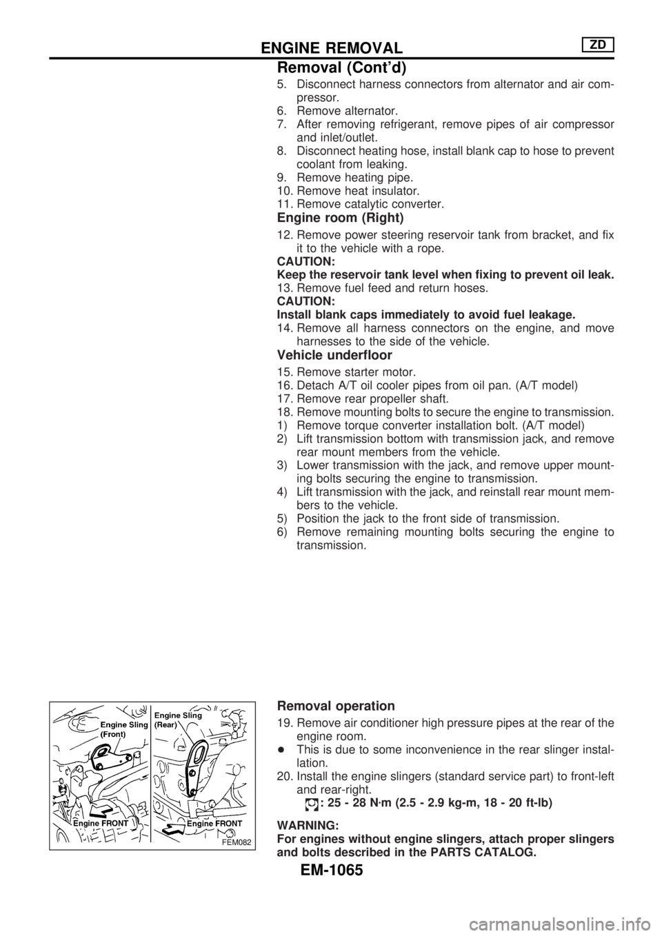
20. Install the engine slingers (standard service part) to front-left
and rear-right.
:25-28Nzm (2.5 - 2.9 kg-m, 18 - 20 ft-lb)
WARNING:
For engines without engine slingers, attach proper slingers
and bolts described in the PARTS CATALOG.
FEM082
ENGINE REMOVALZD
Removal (Cont'd)
EM-1065
Page 804 of 1033
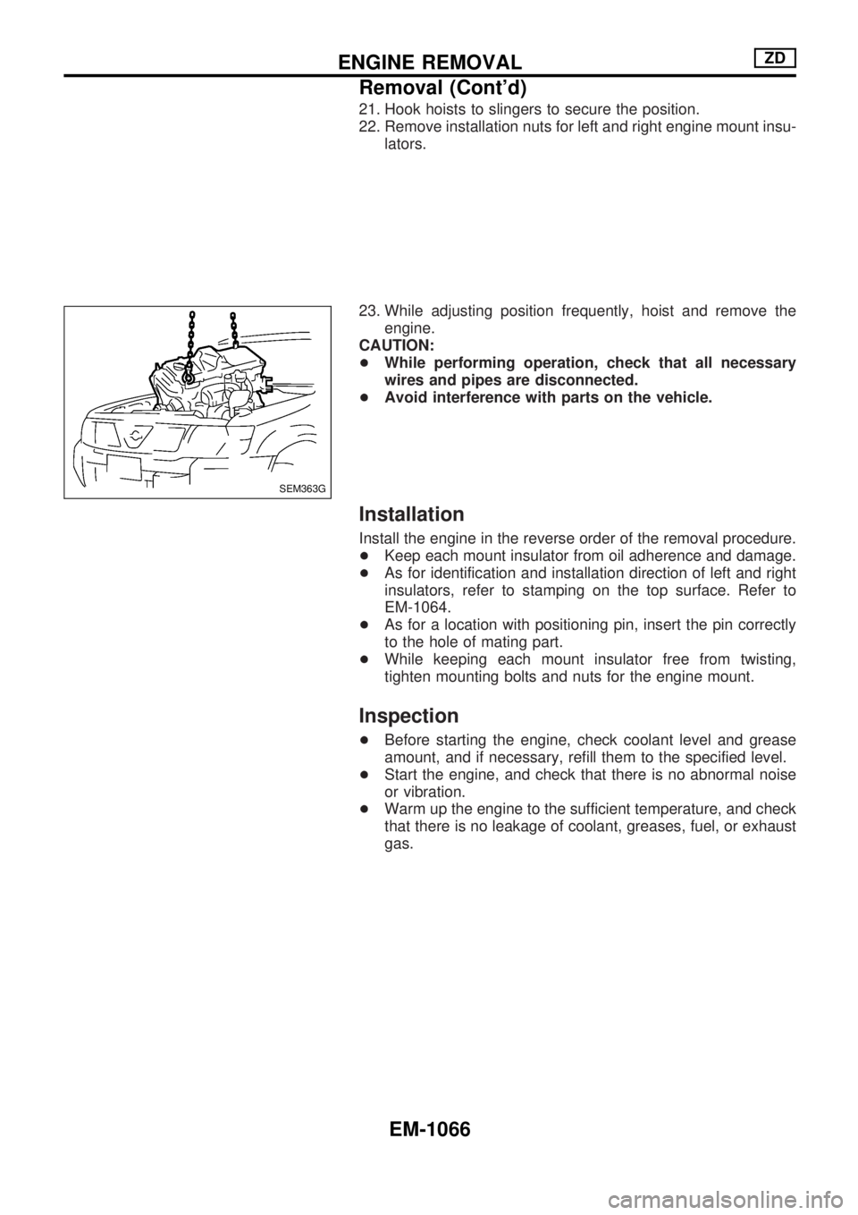
21. Hook hoists to slingers to secure the position.
22. Remove installation nuts for left and right engine mount insu-
lators.
23. While adjusting position frequently, hoist and remove the
engine.
CAUTION:
+While performing operation, check that all necessary
wires and pipes are disconnected.
+Avoid interference with parts on the vehicle.
Installation
Install the engine in the reverse order of the removal procedure.
+Keep each mount insulator from oil adherence and damage.
+As for identification and installation direction of left and right
insulators, refer to stamping on the top surface. Refer to
EM-1064.
+As for a location with positioning pin, insert the pin correctly
to the hole of mating part.
+While keeping each mount insulator free from twisting,
tighten mounting bolts and nuts for the engine mount.
Inspection
+Before starting the engine, check coolant level and grease
amount, and if necessary, refill them to the specified level.
+Start the engine, and check that there is no abnormal noise
or vibration.
+Warm up the engine to the sufficient temperature, and check
that there is no leakage of coolant, greases, fuel, or exhaust
gas.
SEM363G
ENGINE REMOVALZD
Removal (Cont'd)
EM-1066
Page 807 of 1033
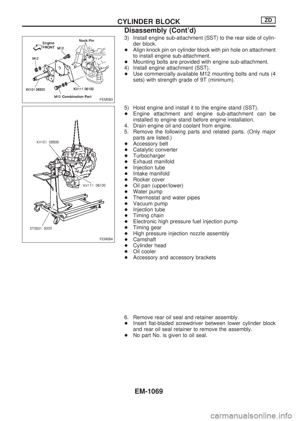
3) Install engine sub-attachment (SST) to the rear side of cylin-
der block.
+Align knock pin on cylinder block with pin hole on attachment
to install engine sub-attachment.
+Mounting bolts are provided with engine sub-attachment.
4) Install engine attachment (SST).
+Use commercially available M12 mounting bolts and nuts (4
sets) with strength grade of 9T (minimum).
5) Hoist engine and install it to the engine stand (SST).
+Engine attachment and engine sub-attachment can be
installed to engine stand before engine installation.
4. Drain engine oil and coolant from engine.
5. Remove the following parts and related parts. (Only major
parts are listed.)
+Accessory belt
+Catalytic converter
+Turbocharger
+Exhaust manifold
+Injection tube
+Intake manifold
+Rocker cover
+Oil pan (upper/lower)
+Water pump
+Thermostat and water pipes
+Vacuum pump
+Injection tube
+Timing chain
+Electronic high pressure fuel injection pump
+Timing gear
+High pressure injection nozzle assembly
+Camshaft
+Cylinder head
+Oil cooler
+Accessory and accessory brackets
6. Remove rear oil seal and retainer assembly.
+Insert flat-bladed screwdriver between lower cylinder block
and rear oil seal retainer to remove the assembly.
+No part No. is given to oil seal.
FEM083
FEM084
CYLINDER BLOCKZD
Disassembly (Cont'd)
EM-1069
Page 813 of 1033
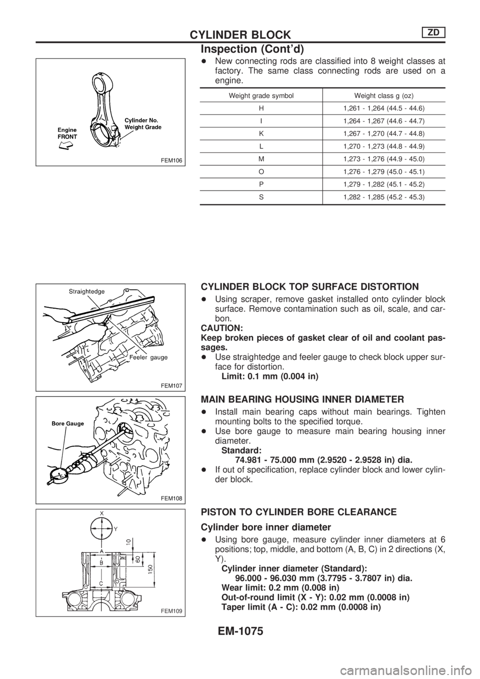
+New connecting rods are classified into 8 weight classes at
factory. The same class connecting rods are used on a
engine.
Weight grade symbol Weight class g (oz)
H 1,261 - 1,264 (44.5 - 44.6)
I 1,264 - 1,267 (44.6 - 44.7)
K 1,267 - 1,270 (44.7 - 44.8)
L 1,270 - 1,273 (44.8 - 44.9)
M 1,273 - 1,276 (44.9 - 45.0)
O 1,276 - 1,279 (45.0 - 45.1)
P 1,279 - 1,282 (45.1 - 45.2)
S 1,282 - 1,285 (45.2 - 45.3)
CYLINDER BLOCK TOP SURFACE DISTORTION
+Using scraper, remove gasket installed onto cylinder block
surface. Remove contamination such as oil, scale, and car-
bon.
CAUTION:
Keep broken pieces of gasket clear of oil and coolant pas-
sages.
+Use straightedge and feeler gauge to check block upper sur-
face for distortion.
Limit: 0.1 mm (0.004 in)
MAIN BEARING HOUSING INNER DIAMETER
+Install main bearing caps without main bearings. Tighten
mounting bolts to the specified torque.
+Use bore gauge to measure main bearing housing inner
diameter.
Standard:
74.981 - 75.000 mm (2.9520 - 2.9528 in) dia.
+If out of specification, replace cylinder block and lower cylin-
der block.
PISTON TO CYLINDER BORE CLEARANCE
Cylinder bore inner diameter
+Using bore gauge, measure cylinder inner diameters at 6
positions; top, middle, and bottom (A, B, C) in 2 directions (X,
Y).
Cylinder inner diameter (Standard):
96.000 - 96.030 mm (3.7795 - 3.7807 in) dia.
Wear limit: 0.2 mm (0.008 in)
Out-of-round limit (X - Y): 0.02 mm (0.0008 in)
Taper limit (A - C): 0.02 mm (0.0008 in)
FEM106
FEM107
FEM108
FEM109
CYLINDER BLOCKZD
Inspection (Cont'd)
EM-1075
Page 819 of 1033
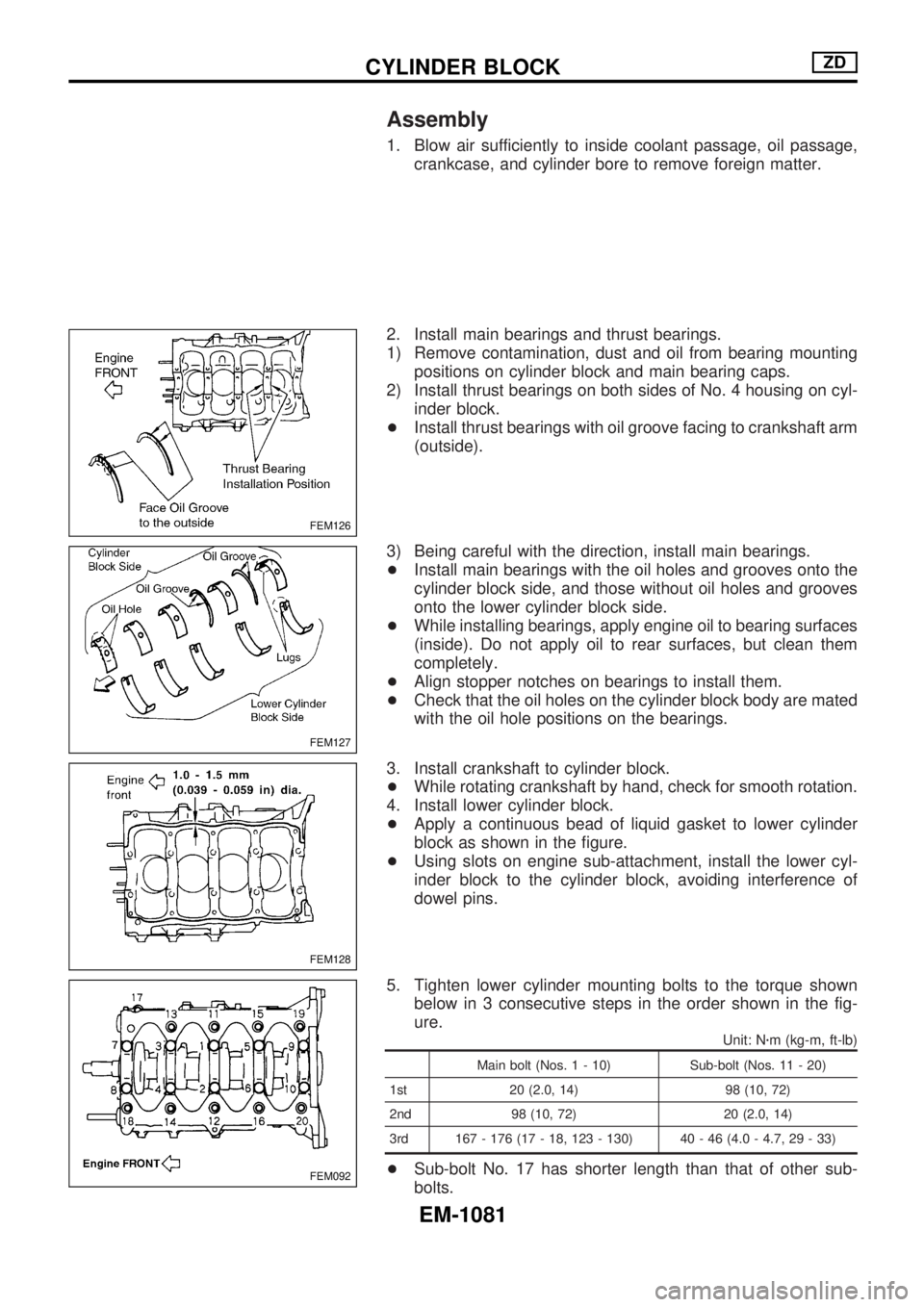
Assembly
1. Blow air sufficiently to inside coolant passage, oil passage,
crankcase, and cylinder bore to remove foreign matter.
2. Install main bearings and thrust bearings.
1) Remove contamination, dust and oil from bearing mounting
positions on cylinder block and main bearing caps.
2) Install thrust bearings on both sides of No. 4 housing on cyl-
inder block.
+Install thrust bearings with oil groove facing to crankshaft arm
(outside).
3) Being careful with the direction, install main bearings.
+Install main bearings with the oil holes and grooves onto the
cylinder block side, and those without oil holes and grooves
onto the lower cylinder block side.
+While installing bearings, apply engine oil to bearing surfaces
(inside). Do not apply oil to rear surfaces, but clean them
completely.
+Align stopper notches on bearings to install them.
+Check that the oil holes on the cylinder block body are mated
with the oil hole positions on the bearings.
3. Install crankshaft to cylinder block.
+While rotating crankshaft by hand, check for smooth rotation.
4. Install lower cylinder block.
+Apply a continuous bead of liquid gasket to lower cylinder
block as shown in the figure.
+Using slots on engine sub-attachment, install the lower cyl-
inder block to the cylinder block, avoiding interference of
dowel pins.
5. Tighten lower cylinder mounting bolts to the torque shown
below in 3 consecutive steps in the order shown in the fig-
ure.
Unit: Nzm (kg-m, ft-lb)
Main bolt (Nos. 1 - 10) Sub-bolt (Nos. 11 - 20)
1st 20 (2.0, 14) 98 (10, 72)
2nd 98 (10, 72) 20 (2.0, 14)
3rd 167 - 176 (17 - 18, 123 - 130) 40 - 46 (4.0 - 4.7, 29 - 33)
+Sub-bolt No. 17 has shorter length than that of other sub-
bolts.
FEM126
FEM127
FEM128
FEM092
CYLINDER BLOCKZD
EM-1081
Page 880 of 1033
A
A/T - Wiring diagram ............................. AT-1009
A/T control ............................................. EC-1148
A/T fluid temperature sensor ................. AT-1081
A/T mode switch .................................... AT-1095
A/T self-diagnoses ................................. AT-1028
A/T shift lock system - Wiring
diagram .............................................. AT-1117
A/T shift lock system ............................. AT-1116
A/T trouble diagnoses ........................... AT-1036
APS - Wiring diagram ........................... EC-1125
ASCD (automatic speed control
device) ............................................... EL-1110
ASCD - Wiring diagram ......................... EL-1111
AT/C - Wiring diagram .......................... EC-1150
Accelerator control system .................... FE-1007
Accelerator position sensor .................. EC-1125
Air bag disposal .................................... RS-1015
Air bag precautions ................................ GI-1002
Air bag ................................................... RS-1003
Air cleaner filter replacement ............... MA-1019
Air conditioner cut control ..................... EC-1021
Air flow meter - See Mass air flow
sensor ................................................ EC-1086
Alternator ............................................... EL-1041
Angular tightening application .............. EM-1003
Anti-lock brake system - Wiring
diagram ............................................. BR-1002
Audio ...................................................... EL-1108
Automatic speed control system - See
ASCD ................................................. EL-1110
Automatic transmission fluid
replacement ...................................... MA-1021
B
BACK/L - Wiring diagram ...................... EL-1051
BOOST - Wiring diagram ...................... EC-1204
Back-up lamp ......................................... EL-1051
Basic inspection .................................... EC-1049
Battery ................................................... EL-1035
Boring/horning cylinder block ............... EM-1075
C
CHARGE - Wiring diagram ................... EL-1040
CKPS - Wiring diagram ........................ EC-1140
CONSULT for engine ............................ EC-1038
CONSULT general information .............. GI-1003
COOL/F - Wiring diagram ..................... EC-1105
CORNER - Wiring diagram ................... EL-1054
Camshaft inspection ............................. EM-1032
Charging system .................................... EL-1040
Chassis and body maintenance ........... MA-1020
Clutch operating cylinder ....................... CL-1003
Collision diagnosis ................................ RS-1052
Combination meter ................................ EL-1073Combination switch ............................... EL-1042
Compression pressure ......................... EM-1010
Compressor mounting ........................... HA-1023
Connecting rod bearing clearance ....... EM-1078
Connecting rod bushing clearance ....... EM-1074
Connecting rod ..................................... EM-1074
Control valve (A/T) ................................ AT-1148
Converter housing installation ............... AT-1128
Coolant mixture ratio ............................ MA-1010
Coolant replacement ............................ MA-1014
Cooling fan control ................................ EC-1105
Cornering lamp ...................................... EL-1054
Crankcase emission control system -
See Positive crankcase ventilation ... EC-1022
Crankcase ventilation system - See
Positive crankcase ventilation ........... EC-1022
Crankshaft position sensor (TDC) ........ EC-1140
Crankshaft ............................................ EM-1077
Cruise control - See ASCD ................... EL-1110
Cylinder block boring ............................ EM-1020
Cylinder block ....................................... EM-1067
Cylinder head bolt tightening ................ EM-1034
Cylinder head ....................................... EM-1053
D
DEF - Wiring diagram ............................ EL-1102
DTRL - Wiring diagram ......................... EL-1044
Data link connector for Consult ............ EC-1038
Daytime light system ............................. EL-1044
Diagnosis sensor unit ........................... RS-1008
Diagnostic trouble code (DTC) for
OBD system ...................................... EC-1032
Dome light - See Interior lamp .............. EL-1067
Door mirror ............................................ BT-1007
Door trim ................................................ BT-1004
Drive belt inspection ............................. MA-1011
Drive plate runout ................................. EM-1095
Dropping resistor (A/T) .......................... AT-1086
E
ECCS-D control module .. EC-1068, 1117, 1189,
1191, 1196, 1200
ECM input/output signal ........................ EC-1068
ECTS - Wiring diagram ......................... EC-1092
EGR - Wiring diagram .......................... EC-1209
EGR volume control valve .................... EC-1207
Electrical unit ......................................... EL-1231
Electrical units location .......................... EL-1185
Electronic fuel injection pump .... EC-1119, 1153,
1159, 1165, 1171, 1177, 1180, 1215
Engine control circuit diagram .............. EC-1015
Engine control component parts
location .............................................. EC-1011
Engine control system diagram and
chart .................................................. EC-1016
ALPHABETICAL INDEX
IDX-1002
Page 881 of 1033
Engine coolant temperature sensor
(ECTS) .............................................. EC-1092
Engine oil filter replacement ................. MA-1013
Engine oil replacement ......................... MA-1012
Engine removal ..................................... EM-1064
Engine serial number ............................. GI-1008
F
F/FOG - Wiring diagram ........................ EL-1052
Final drive disassembly .............. PD-1004, 1005
Fluid temperature sensor (A/T) ............. AT-1081
Fluids .................................................... MA-1008
Flywheel runout .................................... EM-1095
Fog lamp, front ...................................... EL-1052
Fog lamp, rear ....................................... EL-1053
Forward clutch ....................................... AT-1167
Front axle .............................................. FA-1002
Front final drive disassembly (4WD) .... PD-1004
Front fog lamp ....................................... EL-1052
Front passenger air bag ....................... RS-1003
Front seat .............................................. BT-1006
Front washer .......................................... EL-1098
Front wiper ............................................. EL-1098
Fuel cut control (at no load & high
engine speed) ................................... EC-1021
Fuel filter replacement .......................... MA-1017
Fuel gauge ............................................. EL-1073
Fuel injection system ............................ EC-1019
Fuel line inspection ............................... MA-1018
Fuel precautions ..................................... GI-1002
Fuse block ............................................. EL-1229
Fuse ....................................................... EL-1230
Fusible link ............................................. EL-1230
G
GLOW - Wiring diagram ....................... EC-1221
Gauges .................................................. EL-1073
Glow plug .............................................. EC-1221
Glow relay ............................................. EC-1221
Grease ........................................ MA-1008, 1016
Ground distribution ................................ EL-1013
H
HEAT UP - Wiring diagram .................. EC-1242
HEATER - Wiring diagram .................... HA-1005
HLC - Wiring diagram ............................ EL-1099
HORN - Wiring diagram ........................ EL-1100
Harness layout ....................................... EL-1191
Hazard warning lamp ............................ EL-1058
Headlamp washer .................................. EL-1099
Headlamp wiper ..................................... EL-1099
Headlamp .............................................. EL-1044
Heat up switch ...................................... EC-1241
High clutch ............................................. AT-1165Horn ....................................................... EL-1100
How to erase DTC for OBD system ..... EC-1032
I
ILL - Wiring diagram .............................. EL-1061
Identification plate .................................. GI-1008
Idle speed ............................................. EC-1049
Illumination ............................................. EL-1060
Injection nozzle ..................................... EC-1023
Intake manifold ..................................... EM-1012
Interior lamp ........................................... EL-1067
Interior ................................................... BT-1004
J
Junction box (J/B) .................................. EL-1229
L
License lamp ......................................... EL-1046
Lifting points ........................................... GI-1009
Line pressure solenoid valve ................ AT-1086
Line pressure test (A/T) ........................ AT-1044
Liquid gasket application ...................... EM-1003
Location of electrical units ..................... EL-1185
Low and reverse brake ......................... AT-1171
Lubricants ............................................. MA-1008
Luggage room lamp .............................. EL-1067
M
MAFS - Wiring diagram ........................ EC-1086
MAIN - Wiring diagram ......................... EC-1077
MAJOR OVERHALL .............................. AT-1129
METER - Wiring diagram ...................... EL-1073
Maintenance (engine) ........................... MA-1011
Malfunction indicator lamp (MIL) .......... EC-1033
Manifold tightening torque (intake &
exhaust) ............................................ MA-1011
Mass air flow sensor (MAFS) ............... EC-1086
Meter ...................................................... EL-1073
Mirror, door ............................................ BT-1007
Mirror, outside ....................................... BT-1007
Model variation ....................................... GI-1005
N
NATS (Nissan Anti-theft System) .......... EL-1163
NATS - Wiring diagram ......................... EL-1166
NVH troubleshooting (EM) ................... EM-1008
ALPHABETICAL INDEX
IDX-1003
Page 890 of 1033
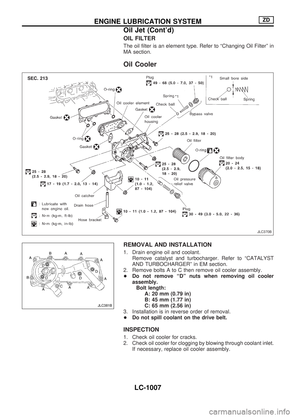
OIL FILTER
The oil filter is an element type. Refer to ªChanging Oil Filterº in
MA section.
Oil Cooler
REMOVAL AND INSTALLATION
1. Drain engine oil and coolant.
Remove catalyst and turbocharger. Refer to ªCATALYST
AND TURBOCHARGERº in EM section.
2. Remove bolts A to C then remove oil cooler assembly.
+Do not remove ªDº nuts when removing oil cooler
assembly.
Bolt length:
A: 20 mm (0.79 in)
B: 45 mm (1.77 in)
C: 65 mm (2.56 in)
3. Installation is in reverse order of removal.
+Do not spill coolant on the drive belt.
INSPECTION
1. Check oil cooler for cracks.
2. Check oil cooler for clogging by blowing through coolant inlet.
If necessary, replace oil cooler assembly.
JLC370B
JLC381B
ENGINE LUBRICATION SYSTEMZD
Oil Jet (Cont'd)
LC-1007