2000 NISSAN PATROL window
[x] Cancel search: windowPage 653 of 1033
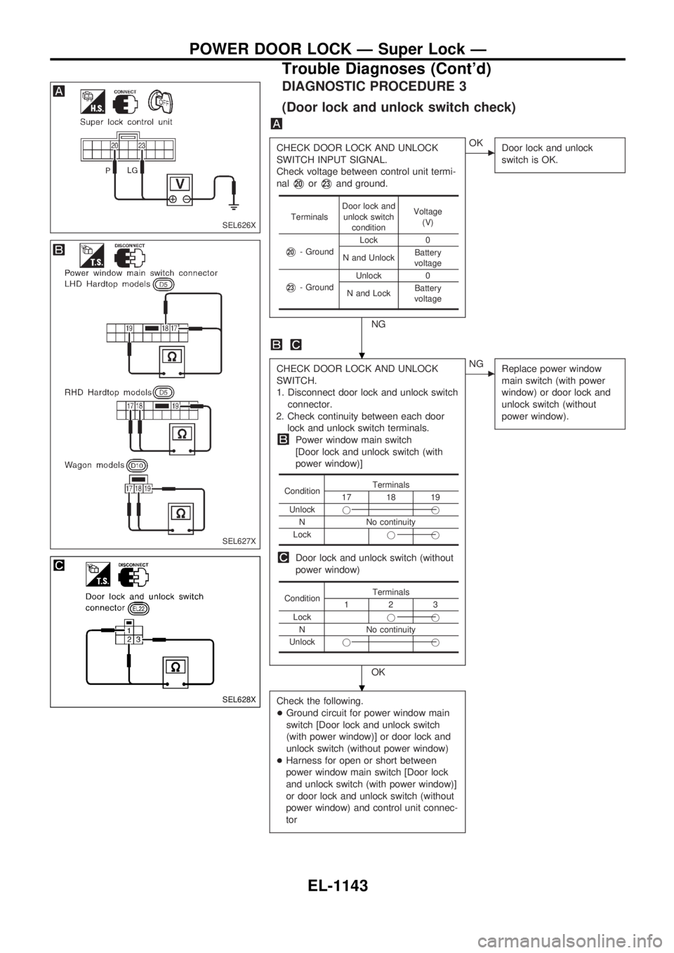
DIAGNOSTIC PROCEDURE 3
(Door lock and unlock switch check)
CHECK DOOR LOCK AND UNLOCK
SWITCH INPUT SIGNAL.
Check voltage between control unit termi-
nal
V20orV23and ground.
NG
cOK
Door lock and unlock
switch is OK.
CHECK DOOR LOCK AND UNLOCK
SWITCH.
1. Disconnect door lock and unlock switch
connector.
2. Check continuity between each door
lock and unlock switch terminals.
Power window main switch
[Door lock and unlock switch (with
power window)]
Door lock and unlock switch (without
power window)
OK
cNG
Replace power window
main switch (with power
window) or door lock and
unlock switch (without
power window).
Check the following.
+Ground circuit for power window main
switch [Door lock and unlock switch
(with power window)] or door lock and
unlock switch (without power window)
+Harness for open or short between
power window main switch [Door lock
and unlock switch (with power window)]
or door lock and unlock switch (without
power window) and control unit connec-
tor
TerminalsDoor lock and
unlock switch
conditionVoltage
(V)
V20- GroundLock 0
N and UnlockBattery
voltage
V23- GroundUnlock 0
N and LockBattery
voltage
ConditionTerminals17 18 19
Unlockjj
N No continuity
Lockjj
ConditionTerminals123
Lockjj
N No continuity
Unlockjj
SEL626X
SEL627X
SEL628X
.
.
POWER DOOR LOCK Ð Super Lock Ð
Trouble Diagnoses (Cont'd)
EL-1143
Page 669 of 1033
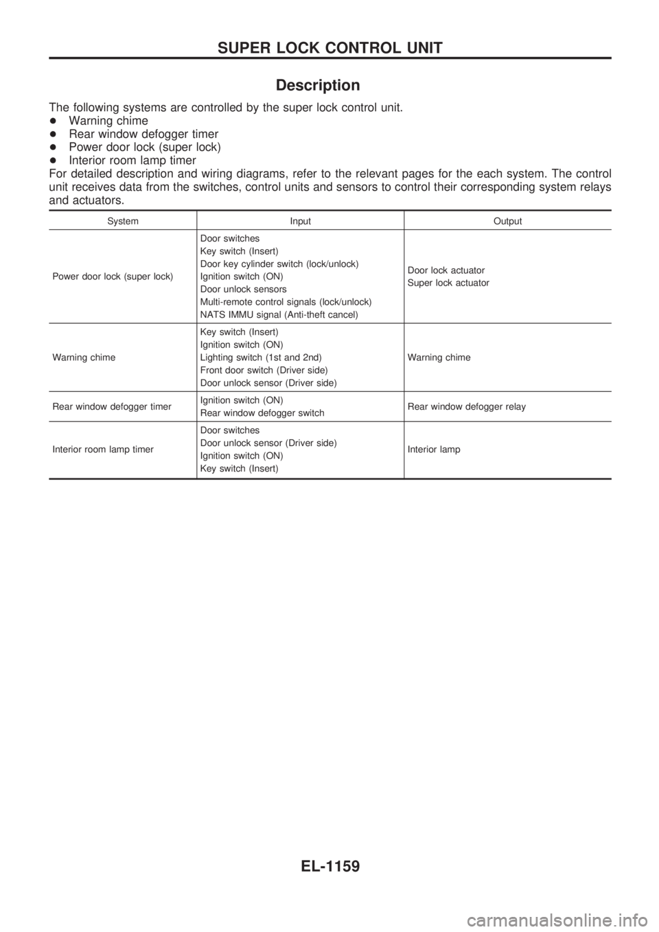
Description
The following systems are controlled by the super lock control unit.
+Warning chime
+Rear window defogger timer
+Power door lock (super lock)
+Interior room lamp timer
For detailed description and wiring diagrams, refer to the relevant pages for the each system. The control
unit receives data from the switches, control units and sensors to control their corresponding system relays
and actuators.
System Input Output
Power door lock (super lock)Door switches
Key switch (Insert)
Door key cylinder switch (lock/unlock)
Ignition switch (ON)
Door unlock sensors
Multi-remote control signals (lock/unlock)
NATS IMMU signal (Anti-theft cancel)Door lock actuator
Super lock actuator
Warning chimeKey switch (Insert)
Ignition switch (ON)
Lighting switch (1st and 2nd)
Front door switch (Driver side)
Door unlock sensor (Driver side)Warning chime
Rear window defogger timerIgnition switch (ON)
Rear window defogger switchRear window defogger relay
Interior room lamp timerDoor switches
Door unlock sensor (Driver side)
Ignition switch (ON)
Key switch (Insert)Interior lamp
SUPER LOCK CONTROL UNIT
EL-1159
Page 672 of 1033
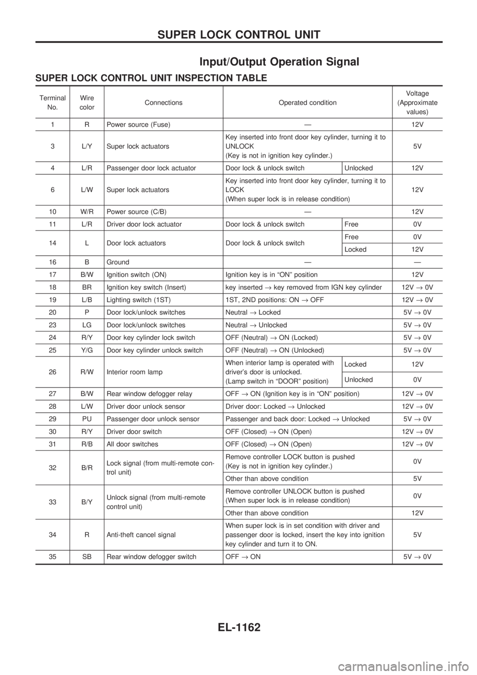
Input/Output Operation Signal
SUPER LOCK CONTROL UNIT INSPECTION TABLE
Terminal
No.Wire
colorConnections Operated conditionVoltage
(Approximate
values)
1 R Power source (Fuse) Ð 12V
3 L/Y Super lock actuatorsKey inserted into front door key cylinder, turning it to
UNLOCK
(Key is not in ignition key cylinder.)5V
4 L/R Passenger door lock actuator Door lock & unlock switch Unlocked 12V
6 L/W Super lock actuatorsKey inserted into front door key cylinder, turning it to
LOCK
(When super lock is in release condition)12V
10 W/R Power source (C/B) Ð 12V
11 L/R Driver door lock actuator Door lock & unlock switch Free 0V
14 L Door lock actuators Door lock & unlock switchFree 0V
Locked 12V
16 B Ground Ð Ð
17 B/W Ignition switch (ON) Ignition key is in ªONº position 12V
18 BR Ignition key switch (Insert) key inserted®key removed from IGN key cylinder 12V®0V
19 L/B Lighting switch (1ST) 1ST, 2ND positions: ON®OFF 12V®0V
20 P Door lock/unlock switches Neutral®Locked 5V®0V
23 LG Door lock/unlock switches Neutral®Unlocked 5V®0V
24 R/Y Door key cylinder lock switch OFF (Neutral)®ON (Locked) 5V®0V
25 Y/G Door key cylinder unlock switch OFF (Neutral)®ON (Unlocked) 5V®0V
26 R/W Interior room lampWhen interior lamp is operated with
driver's door is unlocked.
(Lamp switch in ªDOORº position)Locked 12V
Unlocked 0V
27 B/W Rear window defogger relay OFF®ON (Ignition key is in ªONº position) 12V®0V
28 L/W Driver door unlock sensor Driver door: Locked®Unlocked 12V®0V
29 PU Passenger door unlock sensor Passenger and back door: Locked®Unlocked 5V®0V
30 R/Y Driver door switch OFF (Closed)®ON (Open) 12V®0V
31 R/B All door switches OFF (Closed)®ON (Open) 12V®0V
32 B/RLock signal (from multi-remote con-
trol unit)Remove controller LOCK button is pushed
(Key is not in ignition key cylinder.)0V
Other than above condition 5V
33 B/YUnlock signal (from multi-remote
control unit)Remove controller UNLOCK button is pushed
(When super lock is in release condition)0V
Other than above condition 12V
34 R Anti-theft cancel signalWhen super lock is in set condition with driver and
passenger door is locked, insert the key into ignition
key cylinder and turn it to ON.5V
35 SB Rear window defogger switch OFF®ON 5V®0V
SUPER LOCK CONTROL UNIT
EL-1162
Page 736 of 1033
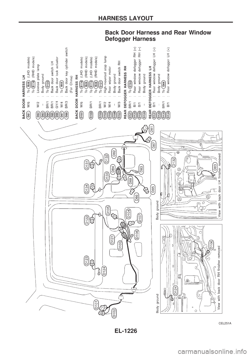
Back Door Harness and Rear Window
Defogger Harness
CEL251A
HARNESS LAYOUT
EL-1226
Page 737 of 1033
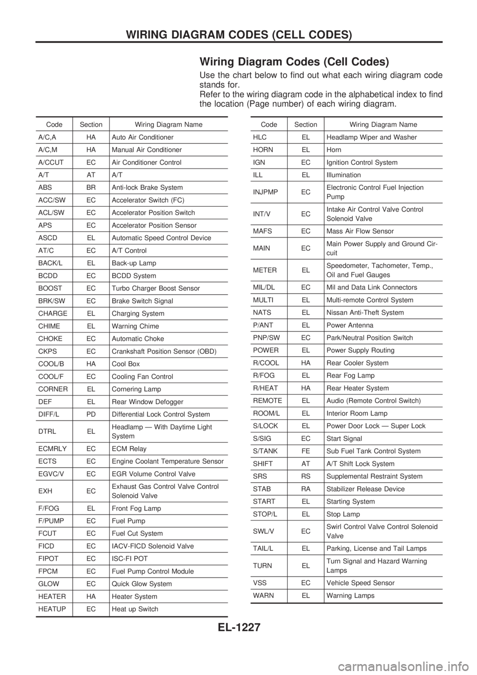
Wiring Diagram Codes (Cell Codes)
Use the chart below to find out what each wiring diagram code
stands for.
Refer to the wiring diagram code in the alphabetical index to find
the location (Page number) of each wiring diagram.
Code Section Wiring Diagram Name
A/C,A HA Auto Air Conditioner
A/C,M HA Manual Air Conditioner
A/CCUT EC Air Conditioner Control
A/T AT A/T
ABS BR Anti-lock Brake System
ACC/SW EC Accelerator Switch (FC)
ACL/SW EC Accelerator Position Switch
APS EC Accelerator Position Sensor
ASCD EL Automatic Speed Control Device
AT/C EC A/T Control
BACK/L EL Back-up Lamp
BCDD EC BCDD System
BOOST EC Turbo Charger Boost Sensor
BRK/SW EC Brake Switch Signal
CHARGE EL Charging System
CHIME EL Warning Chime
CHOKE EC Automatic Choke
CKPS EC Crankshaft Position Sensor (OBD)
COOL/B HA Cool Box
COOL/F EC Cooling Fan Control
CORNER EL Cornering Lamp
DEF EL Rear Window Defogger
DIFF/L PD Differential Lock Control System
DTRL ELHeadlamp Ð With Daytime Light
System
ECMRLY EC ECM Relay
ECTS EC Engine Coolant Temperature Sensor
EGVC/V EC EGR Volume Control Valve
EXH ECExhaust Gas Control Valve Control
Solenoid Valve
F/FOG EL Front Fog Lamp
F/PUMP EC Fuel Pump
FCUT EC Fuel Cut System
FICD EC IACV-FICD Solenoid Valve
FIPOT EC ISC-FI POT
FPCM EC Fuel Pump Control Module
GLOW EC Quick Glow System
HEATER HA Heater System
HEATUP EC Heat up SwitchCode Section Wiring Diagram Name
HLC EL Headlamp Wiper and Washer
HORN EL Horn
IGN EC Ignition Control System
ILL EL Illumination
INJPMP ECElectronic Control Fuel Injection
Pump
INT/V ECIntake Air Control Valve Control
Solenoid Valve
MAFS EC Mass Air Flow Sensor
MAIN ECMain Power Supply and Ground Cir-
cuit
METER ELSpeedometer, Tachometer, Temp.,
Oil and Fuel Gauges
MIL/DL EC Mil and Data Link Connectors
MULTI EL Multi-remote Control System
NATS EL Nissan Anti-Theft System
P/ANT EL Power Antenna
PNP/SW EC Park/Neutral Position Switch
POWER EL Power Supply Routing
R/COOL HA Rear Cooler System
R/FOG EL Rear Fog Lamp
R/HEAT HA Rear Heater System
REMOTE EL Audio (Remote Control Switch)
ROOM/L EL Interior Room Lamp
S/LOCK EL Power Door Lock Ð Super Lock
S/SIG EC Start Signal
S/TANK FE Sub Fuel Tank Control System
SHIFT AT A/T Shift Lock System
SRS RS Supplemental Restraint System
STAB RA Stabilizer Release Device
START EL Starting System
STOP/L EL Stop Lamp
SWL/V ECSwirl Control Valve Control Solenoid
Valve
TAIL/L EL Parking, License and Tail Lamps
TURN ELTurn Signal and Hazard Warning
Lamps
VSS EC Vehicle Speed Sensor
WARN EL Warning Lamps
WIRING DIAGRAM CODES (CELL CODES)
EL-1227
Page 738 of 1033
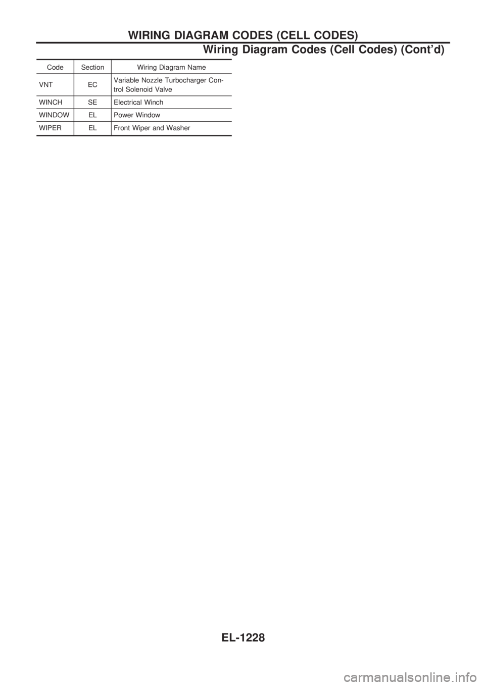
Code Section Wiring Diagram Name
VNT ECVariable Nozzle Turbocharger Con-
trol Solenoid Valve
WINCH SE Electrical Winch
WINDOW EL Power Window
WIPER EL Front Wiper and Washer
WIRING DIAGRAM CODES (CELL CODES)
Wiring Diagram Codes (Cell Codes) (Cont'd)
EL-1228
Page 846 of 1033
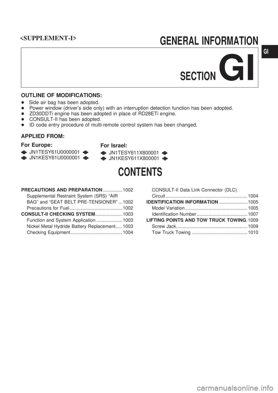
GENERAL INFORMATION
SECTION
GI
OUTLINE OF MODIFICATIONS:
+Side air bag has been adopted.
+Power window (driver's side only) with an interruption detection function has been adopted.
+ZD30DDTi engine has been adopted in place of RD28ETi engine.
+CONSULT-II has been adopted.
+ID code entry procedure of multi-remote control system has been changed.
APPLIED FROM:
For Europe:
JN1TESY61U0000001
JN1KESY61U0000001
For Israel:
JN1TESY611X800001
JN1KESY611X800001
CONTENTS
PRECAUTIONS AND PREPARATION............... 1002
Supplemental Restraint System (SRS) ªAIR
BAGº and ªSEAT BELT PRE-TENSIONERº ... 1002
Precautions for Fuel......................................... 1002
CONSULT-II CHECKING SYSTEM..................... 1003
Function and System Application .................... 1003
Nickel Metal Hydride Battery Replacement ..... 1003
Checking Equipment ........................................ 1004CONSULT-II Data Link Connector (DLC)
Circuit ............................................................... 1004
IDENTIFICATION INFORMATION...................... 1005
Model Variation ................................................ 1005
Identification Number ....................................... 1007
LIFTING POINTS AND TOW TRUCK TOWING. 1009
Screw Jack....................................................... 1009
Tow Truck Towing ........................................... 1010
GI
Page 882 of 1033
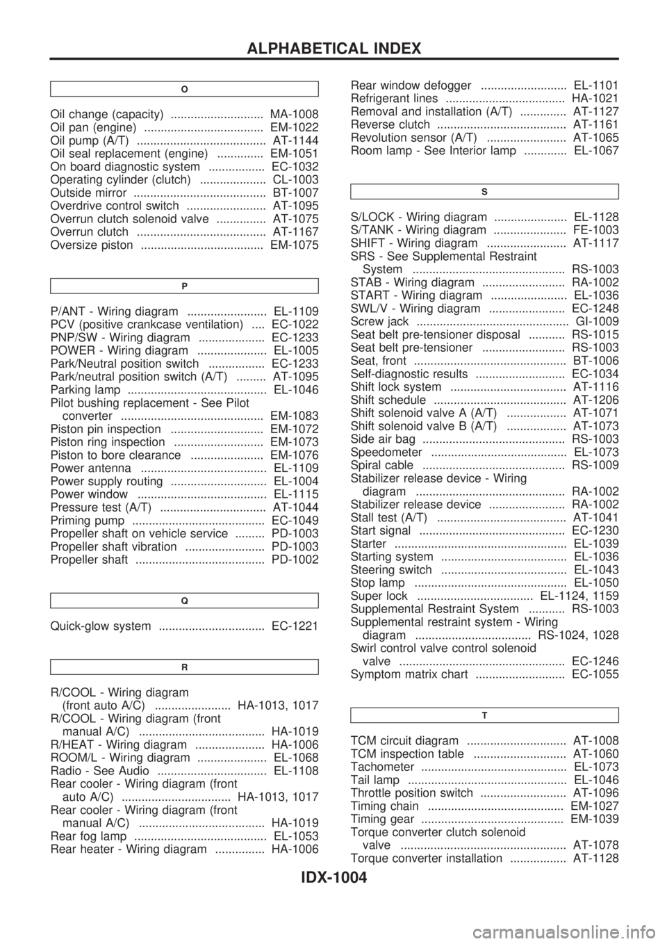
O
Oil change (capacity) ............................ MA-1008
Oil pan (engine) .................................... EM-1022
Oil pump (A/T) ....................................... AT-1144
Oil seal replacement (engine) .............. EM-1051
On board diagnostic system ................. EC-1032
Operating cylinder (clutch) .................... CL-1003
Outside mirror ........................................ BT-1007
Overdrive control switch ........................ AT-1095
Overrun clutch solenoid valve ............... AT-1075
Overrun clutch ....................................... AT-1167
Oversize piston ..................................... EM-1075
P
P/ANT - Wiring diagram ........................ EL-1109
PCV (positive crankcase ventilation) .... EC-1022
PNP/SW - Wiring diagram .................... EC-1233
POWER - Wiring diagram ..................... EL-1005
Park/Neutral position switch ................. EC-1233
Park/neutral position switch (A/T) ......... AT-1095
Parking lamp .......................................... EL-1046
Pilot bushing replacement - See Pilot
converter ........................................... EM-1083
Piston pin inspection ............................ EM-1072
Piston ring inspection ........................... EM-1073
Piston to bore clearance ...................... EM-1076
Power antenna ...................................... EL-1109
Power supply routing ............................. EL-1004
Power window ....................................... EL-1115
Pressure test (A/T) ................................ AT-1044
Priming pump ........................................ EC-1049
Propeller shaft on vehicle service ......... PD-1003
Propeller shaft vibration ........................ PD-1003
Propeller shaft ....................................... PD-1002
Q
Quick-glow system ................................ EC-1221
R
R/COOL - Wiring diagram
(front auto A/C) ....................... HA-1013, 1017
R/COOL - Wiring diagram (front
manual A/C) ...................................... HA-1019
R/HEAT - Wiring diagram ..................... HA-1006
ROOM/L - Wiring diagram ..................... EL-1068
Radio - See Audio ................................. EL-1108
Rear cooler - Wiring diagram (front
auto A/C) ................................. HA-1013, 1017
Rear cooler - Wiring diagram (front
manual A/C) ...................................... HA-1019
Rear fog lamp ........................................ EL-1053
Rear heater - Wiring diagram ............... HA-1006Rear window defogger .......................... EL-1101
Refrigerant lines .................................... HA-1021
Removal and installation (A/T) .............. AT-1127
Reverse clutch ....................................... AT-1161
Revolution sensor (A/T) ........................ AT-1065
Room lamp - See Interior lamp ............. EL-1067
S
S/LOCK - Wiring diagram ...................... EL-1128
S/TANK - Wiring diagram ...................... FE-1003
SHIFT - Wiring diagram ........................ AT-1117
SRS - See Supplemental Restraint
System .............................................. RS-1003
STAB - Wiring diagram ......................... RA-1002
START - Wiring diagram ....................... EL-1036
SWL/V - Wiring diagram ....................... EC-1248
Screw jack .............................................. GI-1009
Seat belt pre-tensioner disposal ........... RS-1015
Seat belt pre-tensioner ......................... RS-1003
Seat, front .............................................. BT-1006
Self-diagnostic results ........................... EC-1034
Shift lock system ................................... AT-1116
Shift schedule ........................................ AT-1206
Shift solenoid valve A (A/T) .................. AT-1071
Shift solenoid valve B (A/T) .................. AT-1073
Side air bag ........................................... RS-1003
Speedometer ......................................... EL-1073
Spiral cable ........................................... RS-1009
Stabilizer release device - Wiring
diagram ............................................. RA-1002
Stabilizer release device ....................... RA-1002
Stall test (A/T) ....................................... AT-1041
Start signal ............................................ EC-1230
Starter .................................................... EL-1039
Starting system ...................................... EL-1036
Steering switch ...................................... EL-1043
Stop lamp .............................................. EL-1050
Super lock ................................... EL-1124, 1159
Supplemental Restraint System ........... RS-1003
Supplemental restraint system - Wiring
diagram ................................... RS-1024, 1028
Swirl control valve control solenoid
valve .................................................. EC-1246
Symptom matrix chart ........................... EC-1055
T
TCM circuit diagram .............................. AT-1008
TCM inspection table ............................ AT-1060
Tachometer ............................................ EL-1073
Tail lamp ................................................ EL-1046
Throttle position switch .......................... AT-1096
Timing chain ......................................... EM-1027
Timing gear ........................................... EM-1039
Torque converter clutch solenoid
valve .................................................. AT-1078
Torque converter installation ................. AT-1128
ALPHABETICAL INDEX
IDX-1004