2000 MITSUBISHI MONTERO ECU
[x] Cancel search: ECUPage 1739 of 1839

SWS -Troubleshooting54B-53
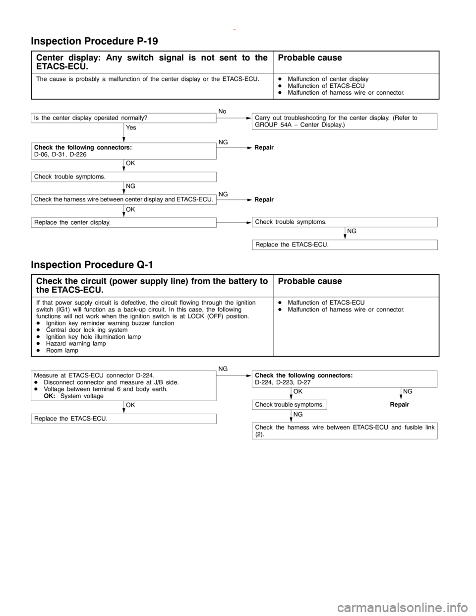
Inspection Procedure P-19
Center display: Any switch signal is not sent to the
ETACS-ECU.Probable cause
The cause is probably a malfunction of the center display or the ETACS-ECU.DMalfunction of center display
DMalfunction of ETACS-ECU
DMalfunction of harness wire or connector.
Ye s
NG
Repair
NG
Replace the ETACS-ECU.
OK
Replace the center display.Check trouble symptoms.
NG
Check the harness wire between center display and ETACS-ECU.NG
Repair
OK
Check trouble symptoms.
Check the following connectors:
D-06, D-31, D-226
Is the center display operated normally?NoCarry out troubleshooting for the center display. (Refer to
GROUP 54A – Center Display.)
Inspection Procedure Q-1
Check the circuit (power supply line) from the battery to
the ETACS-ECU.Probable cause
If that power supply circuit is defective, the circuit flowing through the ignition
switch (IG1) will function as a back-up circuit. In this case, the following
functions will not work when the ignition switch is at LOCK (OFF) position.
DIgnition key reminder warning buzzer function
DCentral door lock ing system
DIgnition key hole illumination lamp
DHazard warninglamp
DRoom lampDMalfunction of ETACS-ECU
DMalfunction of harness wire or connector.
NG
NG
Repair
NG
Check the harness wire between ETACS-ECU and fusible link
(2).
OK
Replace the ETACS-ECU.
OK
Check trouble symptoms.
Check the following connectors:
D-224, D-223, D-27Measure at ETACS-ECU connector D-224.
DDisconnect connector and measure at J/B side.
DVoltage between terminal 6 and body earth.
OK:System voltage
www.WorkshopManuals.co.uk
Purchased from www.WorkshopManuals.co.uk
Page 1746 of 1839

SWS -On-vehicle Service54B-60
ON-VEHICLE SERVICE
ADJUSTMENT PROCEDURES OF SWS FUNCTION
Through special operation of input switches, it is possible to disable and enable the functions listed below.
Settings are retained even if the battery is disconnected.
DKeyless entry hazard answerback function
DInitialization of above mentioned functions
Configuration Mode Entry Conditions
1. Set each switch at the following condition.
DHazard warning lamp switch: OFF
DDiagnosis control: ON (MUT-II
connected or terminal 1 of diagnosis connector connected to earth)
DKey reminder switch: OFF (ignition key inserted)
DIgnition switch: LOCK (OFF)
DDriver’s door switch: OFF (driver’s door closed)
2. When the windshield washer switch is continuously turned ON for more than 10 seconds, the buzzer
integrated in the ETACS-ECU sounds once and the mode is switched to the configuration mode.
Configuration Mode Cancellation Conditions
The ETACS-ECU cancels the configuration mode when any of the conditions listed below is satisfied.
DDiagnosis control: OFF (MUT-II
disconnected or terminal 1 of diagnosis connector disconnected from
earth)
DKey reminder switch: ON (ignition key removed)
DIgnition switch: any position other than LOCK (OFF)
DDriver’s door switch: ON (driver’s door open)
DNo configuration performed within three minutes of entry to configuration mode (If configuration is
performed within first three minutes, monitoring continues for three minutes from that point.)
Configuration of Functions
FunctionConfiguration procedure
Keyless entry hazard
answerbackIf the transmitter’s LOCK switch is turned ON twice within two seconds, the lock answerback
function’s enabled/disabled status is inverted.
D
When function is enabled, buzzer sounds once (initial status).
D
When function is disabled, buzzer sounds twice.
If the transmitter’s UNLOCK switch is turned ON twice within two seconds, the unlock
answerback function’s enabled/disabled status is inverted.
D
When function is enabled, buzzer sounds once (initial status).
D
When function is disabled, buzzer sounds twice.
Initialization of above
mentioned functionsIf the windshield washer switch is turned ON for more than 20 seconds, the buzzer sounds
twice and all functions are initialized. (The configuration mode entry buzzer sounds after 10
seconds, but the switch must be kept ON for 20 seconds to achieve initialization.)
IF the windshield washer switch ins kept ON for more than 20 seconds without prior entry
of the configuration mode, the configuration mode is entered after 10 seconds and
initialization does not take place.
www.WorkshopManuals.co.uk
Purchased from www.WorkshopManuals.co.uk
Page 1748 of 1839

55A-2
HEATER, AIR
CONDITIONER AND
VENTILATION
CONTENTS
SERVICE SPECIFICATIONS 3.................
LUBRICANTS 3..............................
TROUBLESHOOTING
TROUBLESHOOTING
ON-VEHICLE SERVICE 9.....................
Refrigerant Level Test through Performance Test 9.
Magnetic Clutch Test 10.........................
Receiver Drier Test 10..........................
Compressor Drive Belt Adjustment 10.............
Dual Pressure Switch Check 10..................
Charging 11...................................
Performance Test 15............................
Front Blower Relay and Rear Blower Relay
Continuity Check 18............................
Continuity Check of A/C Compressor Relay and
Condernser Fan Relay 18.......................
PTC Heater Relay Continuity Check 19...........
Idle-up Operation Check
Vacuum Actuator Check
Idle-up Solenoid Valve Check 21.................
Clean Air Filter Replacement Procedure 22........
FRONT A/C 23..............................
Air Conditioner Control Panel Assembly and
A/C Switch 23.................................
Heater Unit and Blower Assembly 26.............
Blower Motor and Resistor 29....................
Inside/Outside Air Changeover Damper Motor 30...
Automatic Compressor-ECU and
Air Thermo Sensor Assembly 31.................
REAR HEATER AND REAR COOLER 32.....
Rear A/C Switch, Front Rear Fan Switch 32.......
Rear A/C Control Unit 34........................
Rear Heater Unit 34............................
Rear Heater Unit and Rear Blower Assembly 37....
HEAT SWITCH 40...........................
COMPRESSOR 41...........................
CONDENSER ASSEMBLY AND
CONDENSER FAN 45........................
REFRIGERANT LINE 47.....................
ENGINE COOLANT TEMPERATURE SWITCH
51 ..........................................
IDLE-UP SYSTEM 53........................
DUCTS 54..................................
VENTILATION 56............................
www.WorkshopManuals.co.uk
Purchased from www.WorkshopManuals.co.uk
Page 1750 of 1839

HEATER, AIR CONDITIONER AND VENTILATION - Troubleshooting55A-4
TROUBLESHOOTING
Trouble symp-
tomProbable causeRemedyRefer-
ence
page
The air condi-Malfunction of fuseReplace the fuse.–
tioner does notMalfunction of harness or connectorRepair the harness or connector.–work.
Refrigerant leak or overfilling of refrigerantReplenish the refrigerant, repair the leak
or take out some of the refrigerant.–
A/C compressor relay is defective.Replace the A/C compressor relay.55A-18
The A/C compressor magnetic clutch is
defective.Replace the A/C compressor.55A-10
The dual pressure switch is defective.Replace the dual-pressure switch.55A-10
The A/C switch is defective.Replace the heater control assembly.55A-24
The blower switch is defective.Replace the heater control assembly.55A-24
The air thermo sensor is defective.Replace the automatic compressor-ECU
and the air thermo sensor assembly.55A-31
The automatic compressor-ECU is defec-
tive.Replace the automatic compressor-ECU
and the air thermo sensor assembly.55A-6
The engine-ECU is defective.Replace the engine-ECU.–
When the A/C
is operating,Refrigerant leakReplenish the refrigerant and repair the
leak.–
temperature
inside the pas-The dual pressure switch is defective.Replace the dual-pressure switch.55A-10inside the pas-
senger
The condenser fan relay is defective.Replace the condenser fan relay.55A-18compartment
doesn’t de-
A/C compressor relay is defective.Replace the A/C compressor relay.55A-18
crease (cool
air is not
emitted).The A/C compressor magnetic clutch is
defective.Replace the A/C compressor.55A-10
When the A/C
is operating,
temperature
inside the pas-
senger
compartment
doesn’t in-
crease (warm
air is not
emitted).Malfunction of the air thermo sensorReplace the automatic compressor-ECU
and the air thermo sensor assembly.55A-31
The blowerMalfunction of fuseReplace the fuse.–
motor does notMalfunction of harness or connectorRepair the harness or connector.–run.
The blower relay is defective.Replace the blower relay.55A-18
The blower motor is defective.Replace the blower motor.55A-29
The blower switch is defective.Replace the heater control assembly.55A-24
Malfunction of the resistorReplace the resistor.55A-29
The automatic compressor-ECU is defec-
tive.Replace the automatic compressor-ECU
and the air thermo sensor assembly.55A-6
www.WorkshopManuals.co.uk
Purchased from www.WorkshopManuals.co.uk
Page 1804 of 1839

55B-1
HEATER, AIR
CONDITIONER AND
VENTILATION
CONTENTS
SERVICE SPECIFICATIONS 2.................
LUBRICANTS 2..............................
SPECIAL TOOLS 3...........................
TROUBLESHOOTING
TROUBLESHOOTING
ON-VEHICLE SERVICE 24...................
Magnetic Clutch Test 24.........................
Idle Up Operation Check
FRONT A/C 25..............................
Automatic A/C Control Panel Assembly
(A/C-ECU) 25..................................Blower Linear Controller 26......................
Air Mix Damper Motor and
Air Outlet Changeover Damper Motor 27..........
Heater Water Temperature Sensor 29.............
PHOTO SENSOR 30........................
OUTSIDE AIR TEMPERATURE SENSOR 30..
REAR A/C 30...............................
Electric Motor for Air Outlet Changeover
Damper 30....................................
REFRIGERANT LINE 31.....................
COMPRESSOR 33...........................
www.WorkshopManuals.co.uk
Purchased from www.WorkshopManuals.co.uk
Page 1807 of 1839

HEATER, AIR CONDITIONER AND VENTILATION -Troubleshooting
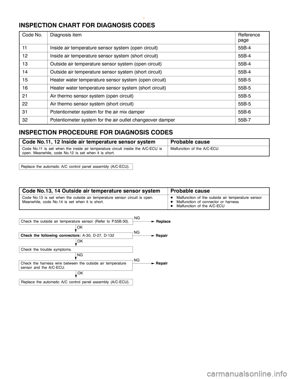
INSPECTION CHART FOR DIAGNOSIS CODES
Code No.Diagnosis itemReference
page
11Inside air temperature sensor system (open circuit)55B-4
12Inside air temperature sensor system (short circuit)55B-4
13Outside air temperature sensor system (open circuit)55B-4
14Outside air temperature sensor system (short circuit)55B-4
15Heater water temperature sensor system (open circuit)55B-5
16Heater water temperature sensor system (short circuit)55B-5
21Air thermo sensor system (open circuit)55B-5
22Air thermo sensor system (short circuit)55B-5
31Potentiometer system for the air mix damper55B-6
32Potentiometer system for the air outlet changeover damper55B-7
INSPECTION PROCEDURE FOR DIAGNOSIS CODES
Code No.11, 12 Inside air temperature sensor systemProbable cause
Code No.11 is set when the inside air temperature circuit inside the A/C-ECU is
open. Meanwhile, code No.12 is set when it is short.Malfunction of the A/C-ECU
Replace the automatic A/C control panelassembly (A/C-ECU).
Code No.13, 14 Outside air temperature sensor systemProbable cause
Code No.13 is set when the outside air temperature sensor circuit is open.
Meanwhile, code No.14 is set when it is short.DMalfunction of the outside air temperature sensor
DMalfunction of connector or harness
DMalfunction of the A/C-ECU
OK
Replace the automatic A/C control panelassembly (A/C-ECU).
NG
Check the harness wire between the outside air temperature
sensor and the A/C-ECU.NG
Repair
OK
Check the trouble symptoms.
OK
Check the following connectors:A-30, D-27, D-132NG
Repair
Check the outside air temperature sensor (Refer to P.55B-30).NG
Replace
www.WorkshopManuals.co.uk
Purchased from www.WorkshopManuals.co.uk
Page 1808 of 1839

HEATER, AIR CONDITIONER AND VENTILATION -Troubleshooting
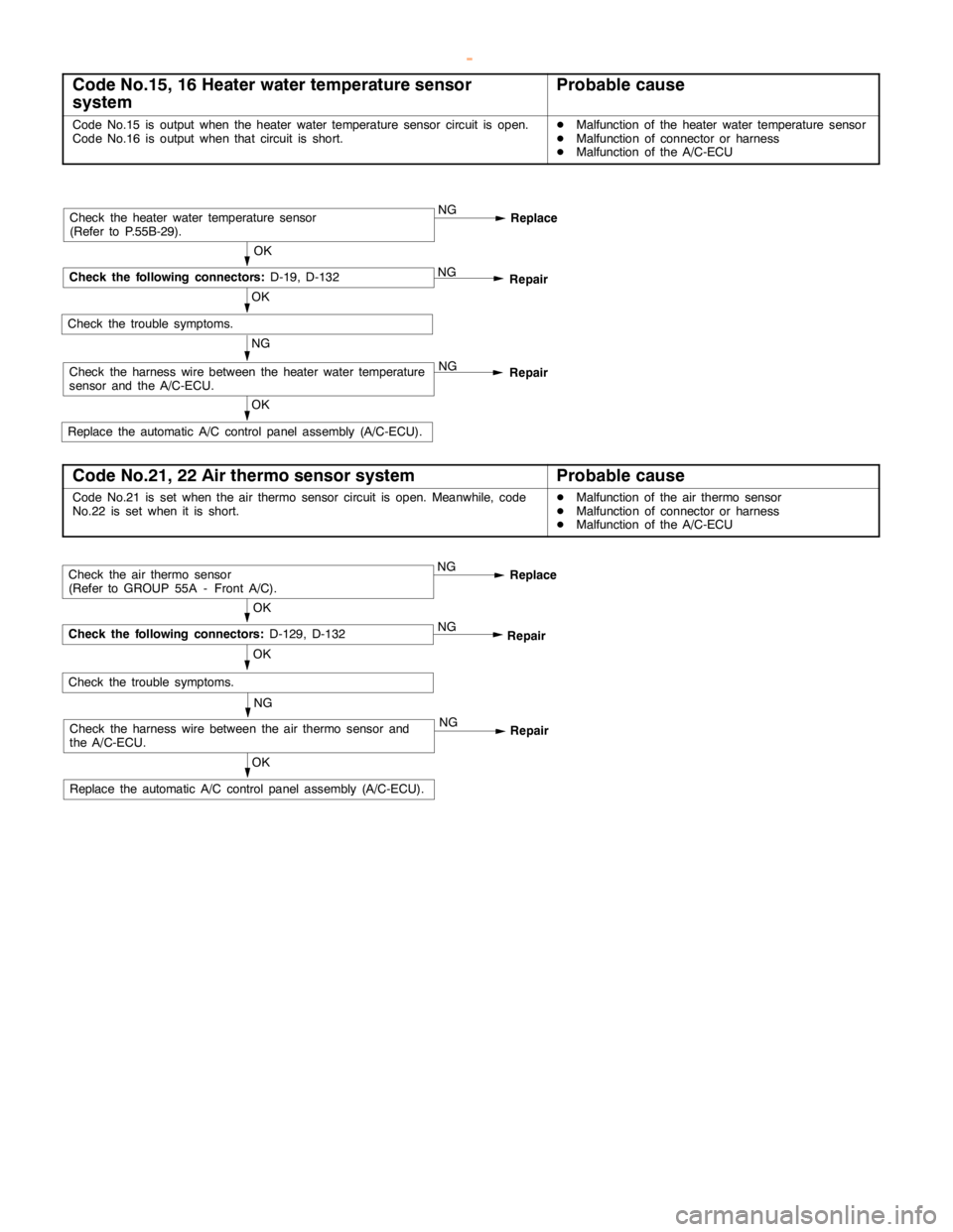
Code No.15, 16 Heater water temperature sensor
systemProbable cause
Code No.15 is output when the heater water temperature sensor circuit is open.
Code No.16 is output when that circuit is short.DMalfunction of the heater water temperature sensor
DMalfunction of connector or harness
DMalfunction of the A/C-ECU
OK
Replace the automatic A/C control panelassembly (A/C-ECU).
NG
Check the harness wire between the heater water temperature
sensor and the A/C-ECU.NG
Repair
OK
Check the trouble symptoms.
OK
Check the following connectors:D-19, D-132NG
Repair
Check the heater water temperature sensor
(Refer to P.55B-29).NG
Replace
Code No.21, 22 Air thermo sensor systemProbable cause
Code No.21 is set when the air thermo sensor circuit is open. Meanwhile, code
No.22 is set when it is short.DMalfunction of the air thermo sensor
DMalfunction of connector or harness
DMalfunction of the A/C-ECU
OK
Replace the automatic A/C control panelassembly (A/C-ECU).
NG
Check the harness wire between the air thermo sensor and
the A/C-ECU.NG
Repair
OK
Check the trouble symptoms.
OK
Check the following connectors:D-129, D-132NG
Repair
Check the air thermo sensor
(Refer to GROUP 55A - Front A/C).NG
Replace
www.WorkshopManuals.co.uk
Purchased from www.WorkshopManuals.co.uk
Page 1809 of 1839

HEATER, AIR CONDITIONER AND VENTILATION -Troubleshooting
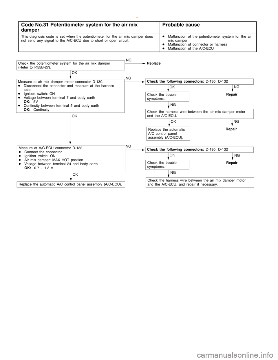
Code No.31 Potentiometer system for the air mix
damperProbable cause
This diagnosis code is set when the potentiometer for the air mix damper does
not send any signal to the A/C-ECU due to short oropencircuit.DMalfunction of the potentiometer system for the air
mix damper
DMalfunction of connector or harness
DMalfunction of the A/C-ECU
NG
Repair
NG
Repair
NG
Check the harness wire between the air mix damper motor
and the A/C-ECU, and repair if necessary.
OK
Replace the automatic A/C control panelassembly (A/C-ECU).
NG
Repair
OK
Replace the automatic
A/C control panel
assembly (A/C-ECU).
OK
Check the trouble
symptoms.
OK
Measure at A/C-ECU connector D-132.
DConnect the connector.
DIgnition switch: ON
DAir mix damper: MAX HOT position
DVoltage between terminal 24 and body earth
OK:0.7 - 1.3 VNGCheck the following connectors:D-130, D-132
NG
Check the harness wire between the air mix damper motor
and the A/C-ECU.
OK
Check the trouble
symptoms.
OK
Measure at air mix damper motor connector D-130.
DDisconnect the connector and measure at the harness
side.
DIgnition switch: ON
DVoltage between terminal 7 and body earth
OK:5V
DContinuity between terminal 5 and body earth
OK:ContinuityNGCheck the following connectors:D-130, D-132
Check the potentiometer system for the air mix damper
(Refer to P.55B-27).NG
Replace
www.WorkshopManuals.co.uk
Purchased from www.WorkshopManuals.co.uk