2000 MITSUBISHI MONTERO light
[x] Cancel search: lightPage 657 of 1839

DIESEL FUEL <4D5-stepIII>-Troubleshooting13E-47
Terminal
No.Normal condition: Inspection conditions (engine status) Check item
21A/C relayA/C switch: OFF→ONSystem voltage→0-1
V
31Idle switchIgnition switch: ONRelease the foot from the
accelerator pedal.0-1V
Step on the accelerator
pedal slightly3 V or higher
32A/C switchA/C in operation (compressor in operation)System voltage
36Selector switch
between A/T and M/TIgnition switch: ONSystem voltage (M/T)
46Control relayIgnition switch: ON0-1V
Ignition switch: ON→OFF (in about 8 seconds)System voltage
51Pump speed sensorEngine: Idling (Use a digital voltage meter to check.)0V↔5V
(repeat the change)
55Accelerator pedal
position sensor (sub)Ignition switch: ONAccelerator pedal: Idling
position0.9 - 1.1 V
Accelerator pedal: Fully
opened position3.7 V or higher
60Sensor power supplyIgnition switch: ON4.6 - 5.4 V
71Ignition switch-STEngine: Cranking8 V or higher
80Back-up power supplyIgnition switch: OFFSystem voltage
81Power supply to accel-
erator pedal position
sensor (main)Ignition switch: ON4.6 - 5.4 V
82Ignition switch-IGIgnition switch: ONSystem voltage
83Engine coolant tem-
perature sensorIgnition switch: ONEngine coolant
temperature: 0_C3.7 - 4.3 V
Engine coolant
temperature: 20_C2.8 - 3.4 V
Engine coolant
temperature: 40_C1.9 - 2.5 V
Engine coolant
temperature: 80_C0.6 - 1.2 V
84Accelerator pedal posi-
tion sensor (main)Ignition switch: ONAccelerator pedal: Idling
position0.9 - 1.1 V
Accelerator pedal: Fully
opened position3.7 V or higher
85Boost pressure sensorIgnition switch: ON (101 kPa)1.0 - 1.4 V
86Vehicle speed sensorDIgnition switch: ON
DMove the vehicle forward slowly0V↔8 - 12 V
(repeat the change)
87Fuel temperature sen-
sor
Ignition switch: ONFuel temperature: 0_C3.2 - 3.6 V
sorFuel temperature: 20_C2.3 - 2.7 V
Fuel temperature: 40_C1.5 - 1.9 V
Fuel temperature: 80_C0.4 - 0.8 V
www.WorkshopManuals.co.uk
Purchased from www.WorkshopManuals.co.uk
Page 1361 of 1839

BODY -Window Glass42-9
HANDLING OF AUTO WINDOW SEALER
Keep the sealant in a cool place, not exposed to the direct
rays of the sun. Do not place any heavy article on the sealant
nor press it, otherwise it will become deformed. Avoid storing
the sealant for more than 6 months, because it will lose its
sealing effect.
BODY PINCH-WELD FLANGE SERVICING
Before servicing the body pinch-weld flange, remove old
adhesive completely. If the flange requires painting, bake
it after painting is completed.
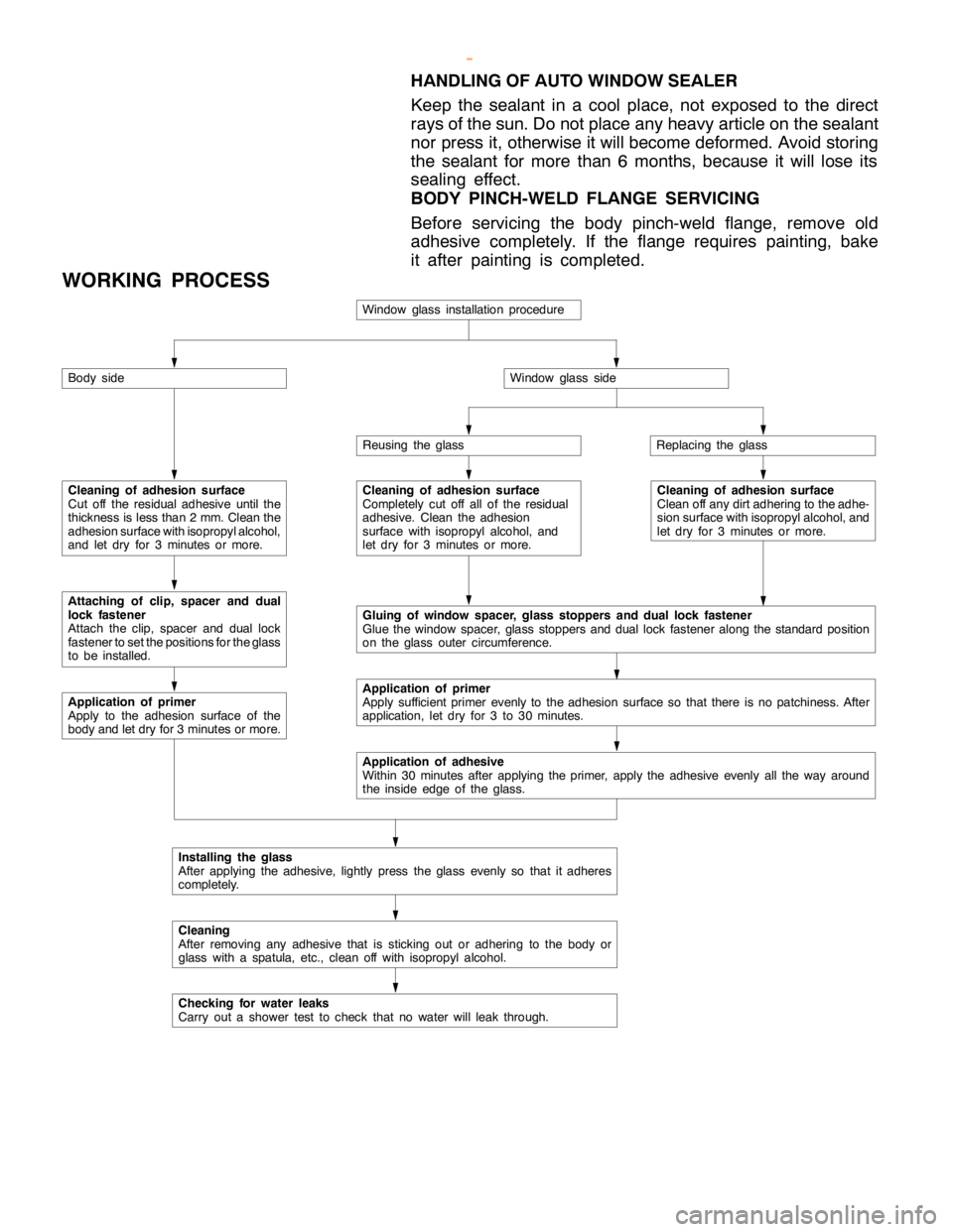
WORKING PROCESS
Window glass installation procedure
Body side
Cleaning of adhesion surface
Cut off the residual adhesive until the
thickness is less than 2 mm. Clean the
adhesion surface with isopropyl alcohol,
and let dry for 3 minutes or more.
Attaching of clip, spacer and dual
lock fastener
Attach the clip, spacer andduallock
fastener to set the positions for the glass
to be installed.
Application of primer
Apply to the adhesion surface of the
body and let dry for 3 minutes or more.
Window glass side
Reusing the glassReplacing the glass
Cleaning of adhesion surface
Completely cut off all of the residual
adhesive. Clean the adhesion
surface with isopropyl alcohol, and
let dry for 3 minutes or more.Cleaning of adhesion surface
Clean off any dirt adhering to the adhe-
sion surface with isopropyl alcohol, and
let dry for 3 minutes or more.
Gluing of window spacer, glass stoppers and dual lock fastener
Glue the window spacer, glass stoppers andduallock fasteneralong the standard position
on the glass outer circumference.
Application of primer
Apply sufficient primer evenly to the adhesion surface so that there is no patchiness. After
application, let dry for 3 to 30 minutes.
Application of adhesive
Within 30 minutes after applying the primer, apply the adhesive evenly all the way around
the inside edge of theglass.
Installing the glass
After applying the adhesive, lightly press the glass evenly so that it adheres
completely.
Cleaning
After removing any adhesive that is sticking out or adhering to the body or
glass with a spatula, etc., clean off with isopropyl alcohol.
Checking for water leaks
Carry out a shower test to check that no water will leak through.
www.WorkshopManuals.co.uk
Purchased from www.WorkshopManuals.co.uk
Page 1573 of 1839

54A-3
ON-VEHICLE SERVICE 46......................
Room Lamp Delay-off Time Adjustment
Procedure 46...............................
REAR COMBINATION LAMP 47...........
SPECIAL TOOLS 47...........................
TROUBLESHOOTING 47.......................
REAR COMBINATION LAMP 47................
HIGH-MOUNTED STOP LAMP 48.........
COLUMN SWITCH 48....................
SPECIAL TOOLS 48...........................
COLUMN SWITCH 48..........................
HAZARD WARNING LAMP SWITCH 50....
SPECIAL TOOLS 50...........................
HAZARD WARNING LAMP SWITCH 50.........
HORN 51................................
CIGARETTE LIGHTER 51.................
ACCESSORY SOCKET 51................
RHEOSTAT 52...........................
CLOCK OR CENTER DISPLAY 53........
TROUBLESHOOTING 53.......................
CLOCK OR CENTER DISPLAY 67..............
RADIO/TAPE PLAYER 68.................
TROUBLESHOOTING 68.......................
RADIO AND CD AUTO CHANGER 81..........
FRONT SPEAKERS 82...................
REAR SPEAKERS 82.....................
ANTENNA83 ............................DEFOGGER 86...........................
TROUBLESHOOTING
ON-VEHICLE SERVICE 86.....................
Printed Heater Check 86.....................
Defogger Relay Continuity Check 86...........
DEFOGGER SWITCH 87.......................
SMART WIRING SYSTEM (SWS)
Refer to GROUP 54B ....................
RADIATOR (RADIATOR FAN MOTOR)
Refer to GROUP 14 ......................
AUTOMATIC TRANSMISSION
Refer to GROUP 23 ......................
ANTI-LOCK BRAKE SYSTEM (ABS)
Refer to GROUP 35B ....................
DOOR HANDLE LATCH (DOOR LOCK)
Refer to GROUP 42 ......................
DOOR GLASS-REGULATOR (POWER
WINDOWS)
Refer to GROUP 42 ......................
KEYLESS ENTRY SYSTEM
Refer to GROUP 42 ......................
WINDSHIELD WIPER/WASHER
Refer to GROUP 51 ......................
REAR WIPER/WASHER
Refer to GROUP 51 ......................
SRS AIRBAG Refer to GROUP 52B......
HEATER Refer to GROUP 55.............
AIR CONDITIONER Refer to GROUP 55...
www.WorkshopManuals.co.uk
Purchased from www.WorkshopManuals.co.uk
Page 1624 of 1839

CHASSIS ELECTRICAL -Clock or Center Display54A-54
BEFORE REMOVING THE BATTERY
The Center display has a large amount of data unique to the vehicle in its memory. When the battery
cable is disconnected, that memory is affected as shown in the table below. Accordingly, it is necessary
to make sure that you take notes of important information before disconnecting the battery cable.
FunctionInput function/memoryWhen battery cable is disconnected
Clock set on displayCurrent timeRetains data for approx. 1 hour
Vehicle model setShort (3-door models)/long (5-door
models)Retains data for approx. 1 hour
Brightness set for displayPosition set on displayRetains data for approx. 1 hour
Unit set for trip computerkm or mile, L/100km or mpg or km/L
Average vehicle speed after resetRetains data for approx. 1 hour
Average vehicle speed on displayAverage vehicle speed after resetRetains data for approx. 1 hour
Average fuel consumption on displayAverage fuel consumption after resetRetains data for approx. 1 hour
Cruising range on displayCruising range, fuel economyRetains data for approx. 1 hour
Outside temperature on displayOutside temperature after the ignition
switch is turned to the OFF(LOCK)
position.Retains data for approx. 1 hour
* The outside temperature sensor
is located near the engine.
Therefore, incorrectly high
temperature may be displayed
when the battery cable is
reconnected within one hour.
DIAGNOSIS FUNCTION FOR CENTER DISPLAY
Center display has the following diagnosis function:
FunctionContents
Service functionThere are the following 4 diagnosis modes available
1. Check of vehicle informationThe vehicle, short (3-door models)/long (5-door models) set
2. Check of LCD segmentsThe LCD segments for display available to light on or not
3. Check of sensorsOutside temperature, voltage of fuel gauge unit, system voltage, fuel amount
remains, fuel economy calculated after supply of fuel
4. Check of units connected into
the center displayThe units connected on display
Voltage (%) on terminal for MUT-II
Vehicle speed signal sent by engine-ECU
Oscillating signal
www.WorkshopManuals.co.uk
Purchased from www.WorkshopManuals.co.uk
Page 1635 of 1839

CHASSIS ELECTRICAL -Clock or Center Display54A-65
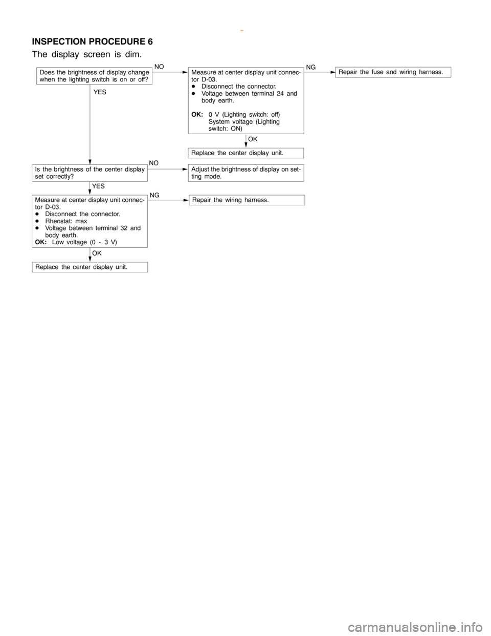
INSPECTION PROCEDURE 6
The display screen is dim.
NOMeasure at center display unit connec-
tor D-03.
DDisconnect the connector.
DVoltage between terminal 24 and
body earth.
OK:0 V (Lighting switch: off)
System voltage (Lighting
switch: ON)NGRepair the fuse and wiring harness.
Is the brightness of the center display
set correctly?NOAdjust the brightness of display on set-
ting mode.
OK
Replace the center display unit.
OK
Replace the center display unit.
YES
Measure at center display unit connec-
tor D-03.
DDisconnect the connector.
DRheostat: max
DVoltage between terminal 32 and
body earth.
OK:Low voltage (0 - 3 V)NGRepair the wiring harness.
Does the brightness of display change
when the lighting switch is on or off?
YES
www.WorkshopManuals.co.uk
Purchased from www.WorkshopManuals.co.uk
Page 1678 of 1839

CHASSIS ELECTRICAL -RV Meter54A-17
Termi-Input/out-
t
Signal sym-
bl
Terminal
lt
Harness problemTrouble symptoms when there is a
hblnal No.
p
put
gy
bolvoltage
(V)Open
circuitshort-cir-
cuit
yp
harness problem
11 - 1 4––––––
15Input/out-
putK (engine
K-LINE
signal)Hi: Sys-
tem volt-
age
Lo:0 - 1ExistsExistsDWiring communication error
DCommunication between the
engine-A/T-ECU
DAbnormal driving information
numerical display
16––––––
17Input/out-
putM-BUSY
(AUDIO)Hi:System
voltage
Lo:0 - 1ExistsExistsDAudio information does not
appear on the screen.
18–SHIELD-
EARTH
(AUDIO)––––
19Input/out-
putM-BUSY
(A/C)Hi:System
voltage
Lo:0 - 1ExistsExistsDAir conditioner information does
not appear on the screen.
DAmbient temperature is not
displayed.
20–SHIELD-
EARTH––––
22 - 21––––––
23InputAmbient
temperature
sensor–ExistsExistsDAmbient temperature is not
displayed.
24InputILL + (Light-
ing switch)Hi:System
voltage
Lo:0 - 1ExistsExistsDoes not illuminate.
25InputACC (ACC
power sup-
l)
System
voltageExists–Screen does not appear. No
operations are possible.
pp
ply)
g
–ExistsBlown multi-purpose fuse
26Input+BSystem
voltageExists–Screen does not appear. No
operations are possible.
g
–ExistsBlown multi-purpose fuse
27InputVSS (Vehicle
speed pulse
signal)Hi:System
voltage
Lo:0 - 1ExistsExistsDAbnormal “Distance km after
replacement” display in mainte-
nance screen
DSwitches which are not
supposed to operate during
driving do operate.
(Example:clock adjustment
screen, maintenance settings,
etc.)
DAmbient temperature display is
abnormally high.
28–Earth–Exists–Screen does not appear.
www.WorkshopManuals.co.uk
Purchased from www.WorkshopManuals.co.uk
Page 1688 of 1839

SWS -General InformationSWS -General Information54B-2
GENERAL INFORMATION
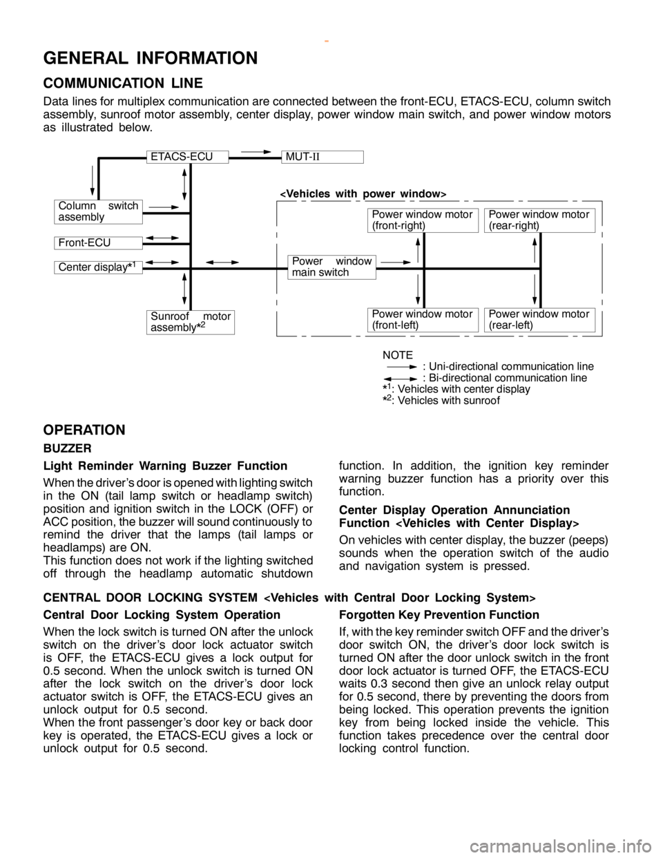
COMMUNICATION LINE
Data lines for multiplex communication are connected between the front-ECU, ETACS-ECU, column switch
assembly, sunroof motor assembly, center display, power window main switch, and power window motors
as illustrated below.
ETACS-ECUMUT-II
Column switch
assembly
Front-ECU
Power window
main switch
Power window motor
(front-right)
Center display*1
Sunroof motor
assembly*2Power window motor
(front-left)
Power window motor
(rear-right)
Power window motor
(rear-left)
NOTE
: Uni-directional communication line
: Bi-directional communication line
*
1: Vehicles with center display
*2: Vehicles with sunroof
OPERATION
BUZZER
Light Reminder Warning Buzzer Function
When the driver’s door is opened with lighting switch
in the ON (tail lamp switch or headlamp switch)
position and ignition switch in the LOCK (OFF) or
ACC position, the buzzer will sound continuously to
remind the driver that the lamps (tail lamps or
headlamps) are ON.
This function does not work if the lighting switched
off through the headlamp automatic shutdownfunction. In addition, the ignition key reminder
warning buzzer function has a priority over this
function.
Center Display Operation Annunciation
Function
On vehicles with center display, the buzzer (peeps)
sounds when the operation switch of the audio
and navigation system is pressed.
CENTRAL DOOR LOCKING SYSTEM
Central Door Locking System Operation
When the lock switch is turned ON after the unlock
switch on the driver’s door lock actuator switch
is OFF, the ETACS-ECU gives a lock output for
0.5 second. When the unlock switch is turned ON
after the lock switch on the driver’s door lock
actuator switch is OFF, the ETACS-ECU gives an
unlock output for 0.5 second.
When the front passenger’s door key or back door
key is operated, the ETACS-ECU gives a lock or
unlock output for 0.5 second.Forgotten Key Prevention Function
If, with the key reminder switch OFF and the driver’s
door switch ON, the driver’s door lock switch is
turned ON after the door unlock switch in the front
door lock actuator is turned OFF, the ETACS-ECU
waits 0.3 second then give an unlock relay output
for 0.5 second, there by preventing the doors from
being locked. This operation prevents the ignition
key from being locked inside the vehicle. This
function takes precedence over the central door
locking control function.
www.WorkshopManuals.co.uk
Purchased from www.WorkshopManuals.co.uk
Page 1689 of 1839

SWS -General Information54B-3
POWER WINDOWS
Power Windows Operation
A signal line dedicated for transmission of multiplex
communication data is connected between the
power window main switches and the power window
motor-ECU.
Communication is uni-directional. The power
window main switches have a transmitting circuit
only, whereas the power window sub switches have
a receiving circuit only.
Power Window Timer Function
With the ignition switch in the ON position, the power
window relay and power window switch receipt
permission signal (a SWS signal transmitted from
the ETACS-ECU) are turned ON [the power windowswitch receipt permission signal remains ON for 30
seconds after the ignition switch is turned LOCK
(OFF)], enabling opening and closing of the
windows. The power window relay goes ON for
additional 30 seconds. If the driver’s door is
subsequently closed during this period, the receipt
permission signal goes OFF. The power window
relay goes OFF 10 seconds after the receipt
permission signal goes OFF.
If the driver’s door is opened during timer operation,
the receipt permission signal goes ON for additional
30 seconds. If the driver’s door is subsequently
closed during this period, the receipt permission
signal goes OFF ten seconds after the receipt
permission signal goes OFF.
KEYLESS ENTRY SYSTEM
Keyless Entry System Operation
If the transmitter LOCK or UNLOCK switch is
pressed while the ignition key is removed and all
of the doors are closed, the doors can be locked
or unlocked.
Keyless Entry Answerback Function
The keyless entry hazard answerable function
facilitates confirmation of door locking and unlock-
ing operations even in daylight. When a LOCKsignal from the keyless entry transmitter is applied
to the ETACS-ECU, all of the turn-signal lamps flash
twice. When an UNLOCK signal from the keyless
entry transmitter is applied to the ETACS-ECU, all of
the turn-signal lamps flash four times. Note that an
unlock switch has change from OFF to ON.
NOTE
The hazard answer back is enabled or disabled
by the configuration function.
SUNROOF
Sunroof Operation
All of the slide open/close, tilt up/down, and stop
operations can be performed by a single switch.
When the roof lid glass is tilted up, the sunshade
opens approximately 98 mm in combined operation
with the roof lid glass for better ventilation.
A jam preventing mechanism has been adopted.
When a slide-close or tilt-down operation is blocked
by an external force, the roof lid glass moves back
and stops.Sunroof Timer Function
When the ignition switch is turned from ON position
to LOCK (OFF) or ACC position, the sunroof will
be ready to work for 30 seconds.
If the driver’s door is opened during the timer
operation, the timer operates for another
30
seconds starting from that point. However, the
timer operation discontinues if the door is closed
during that period.
www.WorkshopManuals.co.uk
Purchased from www.WorkshopManuals.co.uk