2000 MITSUBISHI MONTERO light
[x] Cancel search: lightPage 328 of 1839

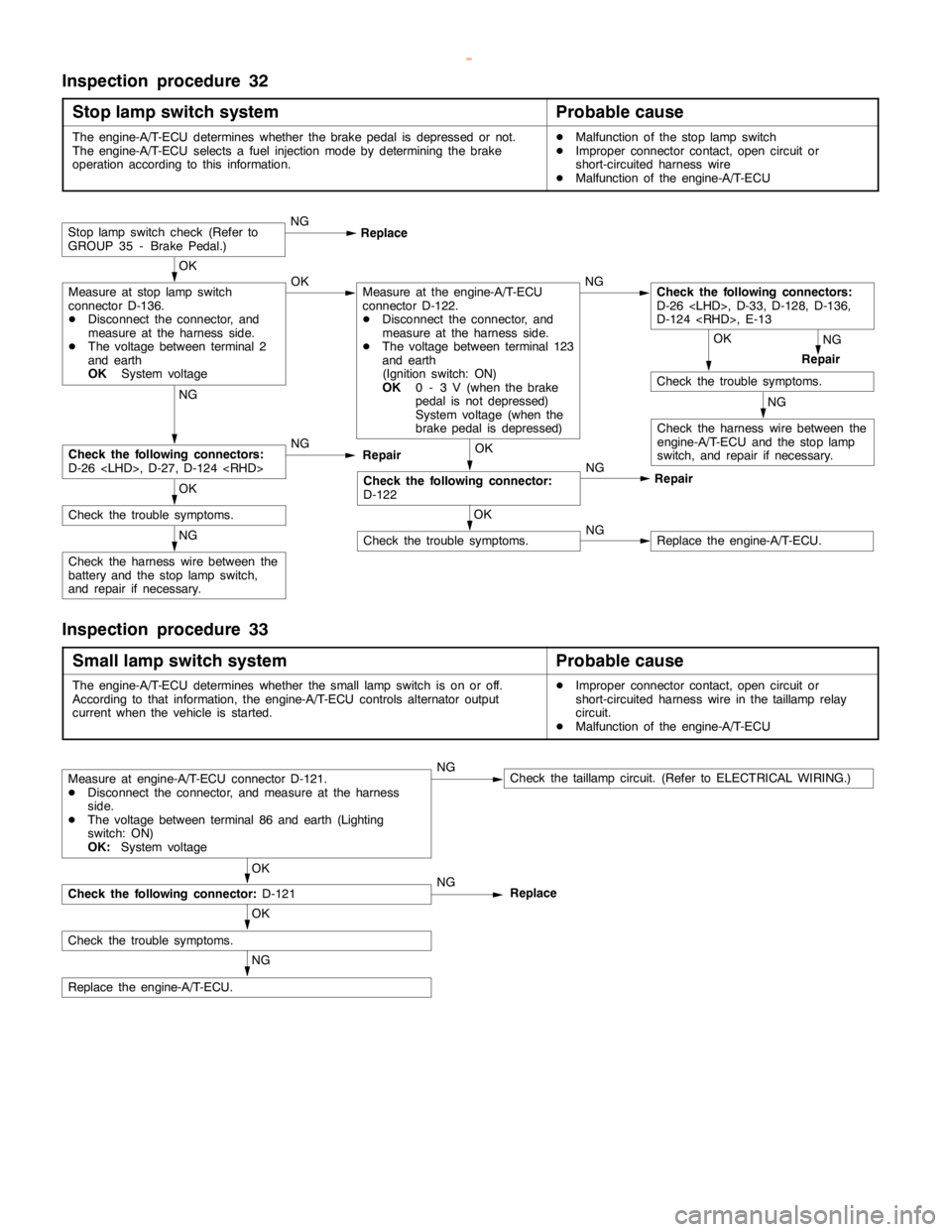
GDI -Troubleshooting
Terminal
No.Normal condition Check requirements (engine condition) Check item
63Stop lamp switchDepress the brake pedal.System voltage
Release the brake pedal.0-3V
65A/C switch (2nd channel)Refer to GROUP 55 - Troubleshooting “Check at the A/C-ECU
terminal, engine-ECU output terminals.”
66Clutch switchDepress the clutch pedal.0-3V
Release the clutch pedal.System voltage
68Ignition switch-STEngine: Cranking8V or more
71Oxygen sensor (front)Engine: Warm up, and then hold the
engine speed at 2,500r/min (Use a
digital voltmeter).0«0.8 V alternates.
76Air flow sensor reset signalEngine: Idling0-1V
Engine: 3,000 r/min6-9V
78Throttle position sensor
(2nd channel)Ignition switch:
ONRelease the
accelerator pedal.4.5 - 5.5 V
Depress the
accelerator pedal
fully.0.4 - 0.6 V
79Accelerator pedal position
switchIgnition switch:
ONRelease the
accelerator pedal.0-1V
Depress the
accelerator pedal
fully.4V or more
80Vehicle speed sensorDIgnition switch: ON
DMove the vehicle forward.0«system voltage
alternates.
83A/C switch (1st channel)Engine: IdlingA/C switch: OFF0-3V
A/C switch: ON
(Compressor is
operating)System voltage
88Small lamp switchLighting switch: OFF0-3V
Lighting switch: ON (Taillamp: ON)System voltage
89Oxygen sensor heaterEngine: Idling0-3V
(front)
Engine: 3,500 r/minSystem voltage
90Oxygen sensor heaterEngine: Idling0-3V
(rear)
Engine: 3,500 r/minSystem voltage
92Fuel pressure sensorEngine: Idling0.3 - 4.7 V
www.WorkshopManuals.co.uk
Purchased from www.WorkshopManuals.co.uk
Page 329 of 1839

GDI -Troubleshooting
Terminal
No.Normal condition Check requirements (engine condition) Check item
94Accelerator pedal position
sensor (1st channel)Ignition switch:
ONRelease the acceler-
ator pedal.0.3 - 1.0 V*1
Depress the
accelerator pedal
fully.4.2 - 5.5 V*2
96Injector open circuit check
signalEngine: Increase engine speed from
idle speed to 4,000 r/min.Decreases slightly (approx.
0.7V) from 4.5 V - 5.0 V.
99Ignition switch - IGIgnition switch: ONSystem voltage
NOTE
Check if the difference in output between *1 and *2 is 4 V or more.
CHECK CHART FOR RESISTANCE AND CONTINUITY
BETWEEN TERMINALS
1. Turn the ignition switch to OFF.
2. Disconnect the engine-ECU connector.
3. Measure the resistance and check for continuity between
the terminals of the engine-ECU harness-side connector
while referring to the check chart.
NOTE
(1) When measuring resistance and checking continuity,
a harness for checking contact pin pressure should
be used instead of inserting a test probe.
(2) Checking need not be carried out in the order given
in the chart.
Caution
If the terminals that should be checked are mistaken,
or if connector terminals are not correctly shorted
to earth, damage may be caused to the vehicle wiring,
sensors, engine-ECU and/or ohmmeter.
Be careful to prevent this!
4. If the ohmmeter shows any deviation from the standard
value, check the corresponding sensor, actuator and
related electrical wiring, and then repair or replace.
5. After repair or replacement, recheck with the ohmmeter
to confirm that the repair or replacement has corrected
the problem.
www.WorkshopManuals.co.uk
Purchased from www.WorkshopManuals.co.uk
Page 368 of 1839
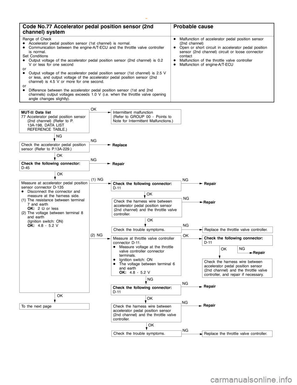
Page 370 of 1839
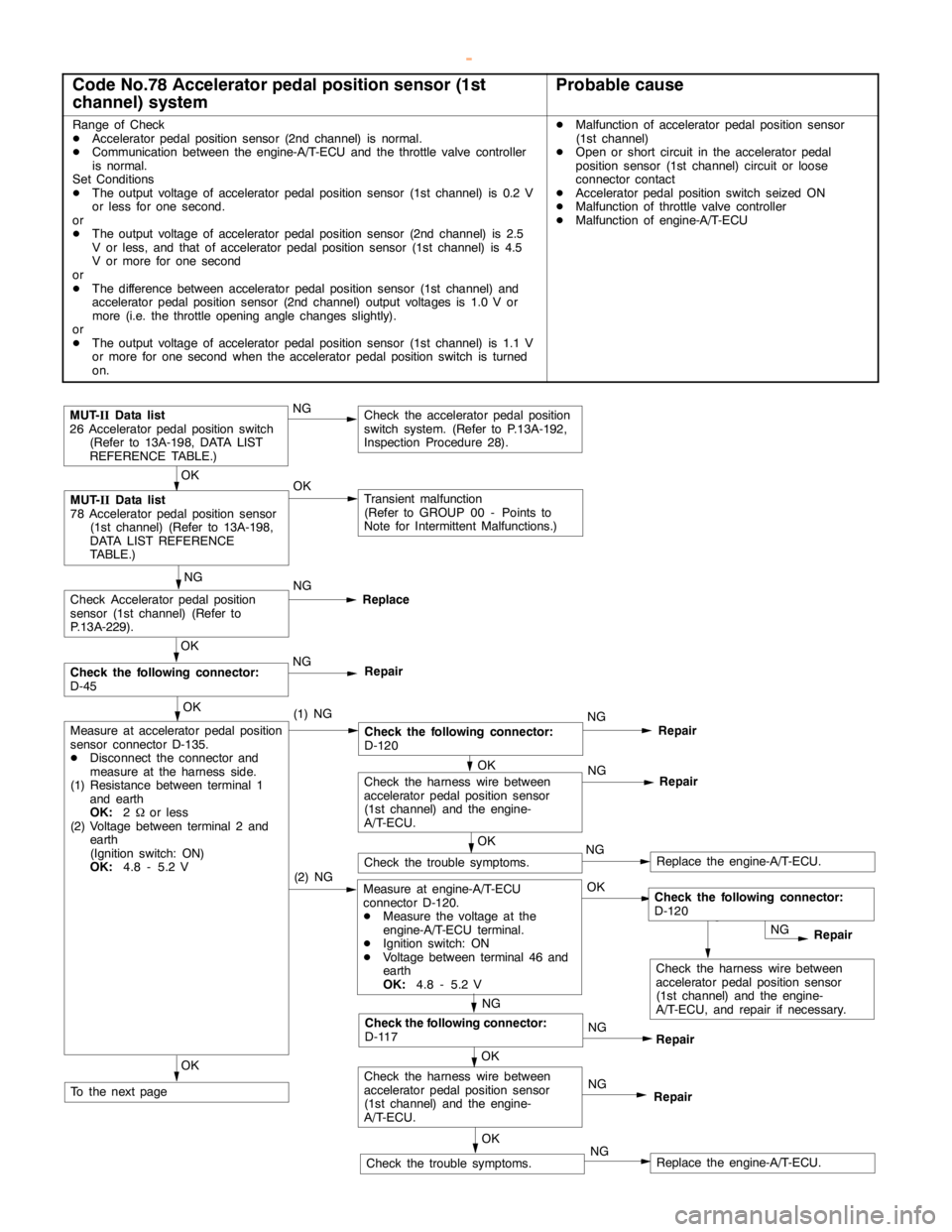
Page 385 of 1839
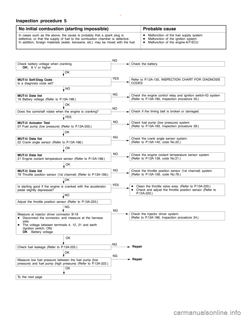
Page 386 of 1839

Page 387 of 1839
Page 409 of 1839
