2000 MITSUBISHI MONTERO light
[x] Cancel search: lightPage 1728 of 1839

SWS -Troubleshooting54B-42
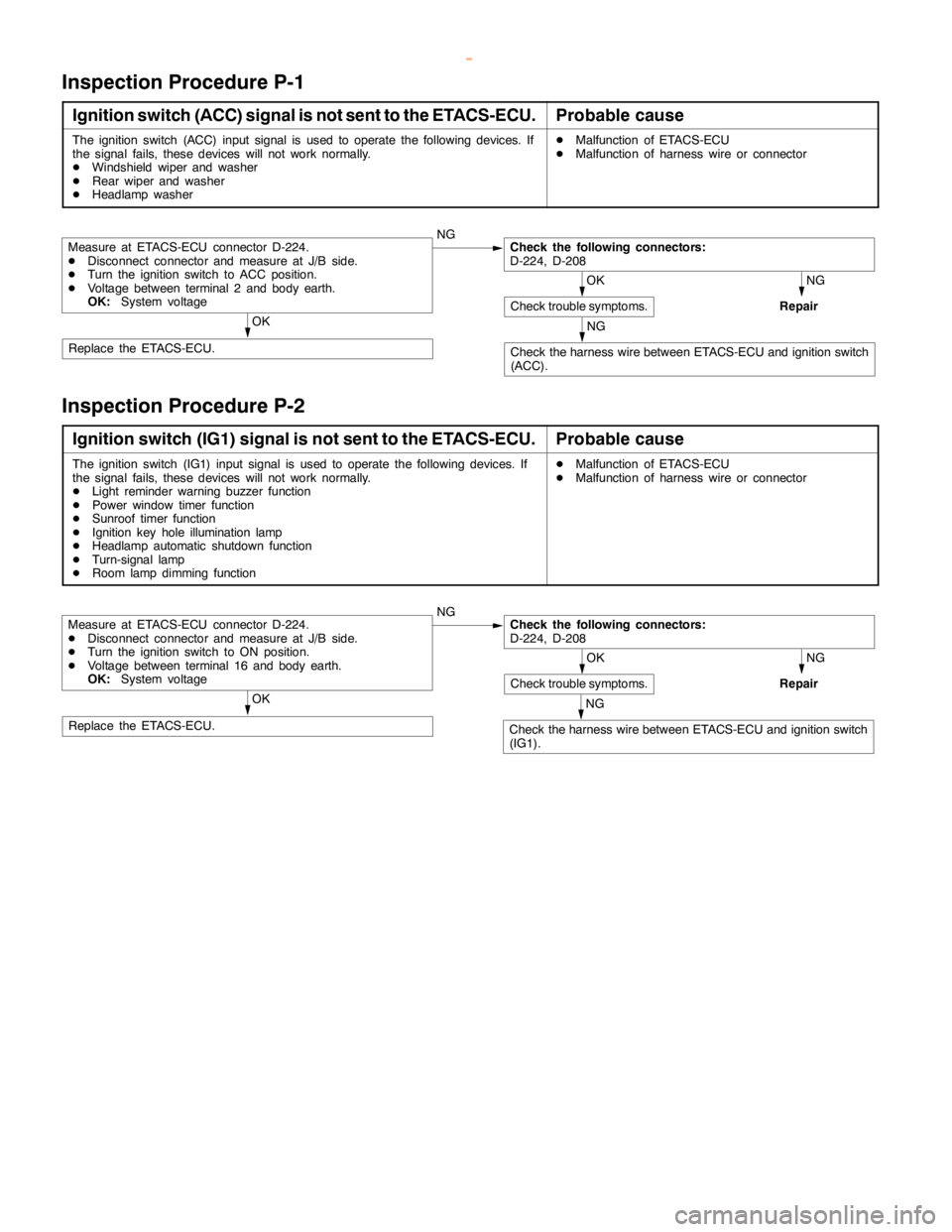
Inspection Procedure P-1
Ignition switch (ACC) signal is not sent to the ETACS-ECU.Probable cause
The ignition switch (ACC) input signal is used to operate the following devices. If
the signal fails, these devices will not work normally.
DWindshield wiper and washer
DRear wiper and washer
DHeadlamp washerDMalfunction of ETACS-ECU
DMalfunction of harness wire or connector
NG
NG
Repair
NG
Check the harness wire between ETACS-ECU and ignition switch
(ACC).
OK
Check trouble symptoms.OK
Replace the ETACS-ECU.
Check the following connectors:
D-224, D-208Measure at ETACS-ECU connector D-224.
DDisconnect connector and measure at J/B side.
DTurn the ignition switch to ACC position.
DVoltage between terminal 2 and body earth.
OK:System voltage
Inspection Procedure P-2
Ignition switch (IG1) signal is not sent to the ETACS-ECU.Probable cause
The ignition switch (IG1) input signal is used to operate the following devices. If
the signal fails, these devices will not work normally.
DLight reminder warning buzzer function
DPower window timer function
DSunroof timer function
DIgnition key hole illumination lamp
DHeadlamp automatic shutdown function
DTurn-signal lamp
DRoom lamp dimming functionDMalfunction of ETACS-ECU
DMalfunction of harness wire or connector
NG
NG
Repair
NG
Check the harness wire between ETACS-ECU and ignition switch
(IG1).
OK
Check trouble symptoms.OK
Replace the ETACS-ECU.
Check the following connectors:
D-224, D-208Measure at ETACS-ECU connector D-224.
DDisconnect connector and measure at J/B side.
DTurn the ignition switch to ON position.
DVoltage between terminal 16 and body earth.
OK:System voltage
www.WorkshopManuals.co.uk
Purchased from www.WorkshopManuals.co.uk
Page 1733 of 1839

SWS -Troubleshooting54B-47
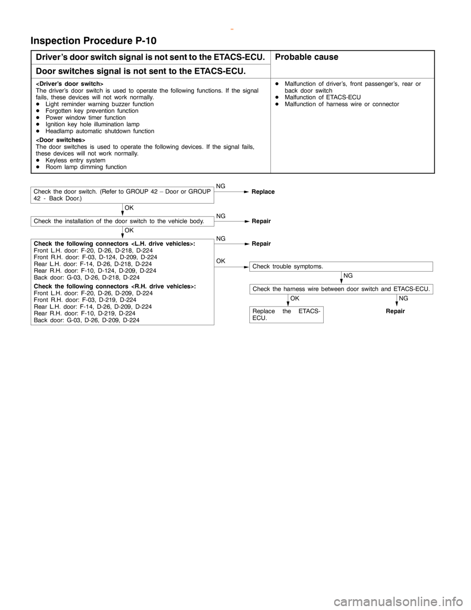
Inspection Procedure P-10
Driver’s door switch signal is not sent to the ETACS-ECU.Probable cause
Door switches signal is not sent to the ETACS-ECU.
The driver’s door switch is used to operate the following functions. If the signal
fails, these devices will not work normally.
DLight reminder warning buzzer function
DForgotten key prevention function
DPower window timer function
DIgnition key hole illumination lamp
DHeadlamp automatic shutdown function
The door switches is used to operate the following devices. If the signal fails,
these devices will not work normally.
DKeyless entry system
DRoom lamp dimming functionDMalfunction of driver’s, front passenger’s, rear or
back door switch
DMalfunction of ETACS-ECU
DMalfunction of harness wire or connector
OK
NG
Repair
OK
NG
Repair
OK
Replace the ETACS-
ECU.
NG
Repair
NG
Check the harness wire between door switch and ETACS-ECU.
OKCheck trouble symptoms.
Check the following connectors
Front L.H. door: F-20, D-26, D-218, D-224
Front R.H. door: F-03, D-124, D-209, D-224
Rear L.H. door: F-14, D-26, D-218, D-224
Rear R.H. door: F-10, D-124, D-209, D-224
Back door: G-03, D-26, D-218, D-224
Check the following connectors
Front L.H. door: F-20, D-26, D-209, D-224
Front R.H. door: F-03, D-219, D-224
Rear L.H. door: F-14, D-26, D-209, D-224
Rear R.H. door: F-10, D-219, D-224
Back door: G-03, D-26, D-209, D-224
Check the installation of the door switch to the vehicle body.
Check the door switch. (Refer to GROUP 42 – Door or GROUP
42 - Back Door.)NG
Replace
www.WorkshopManuals.co.uk
Purchased from www.WorkshopManuals.co.uk
Page 1735 of 1839

SWS -Troubleshooting54B-49
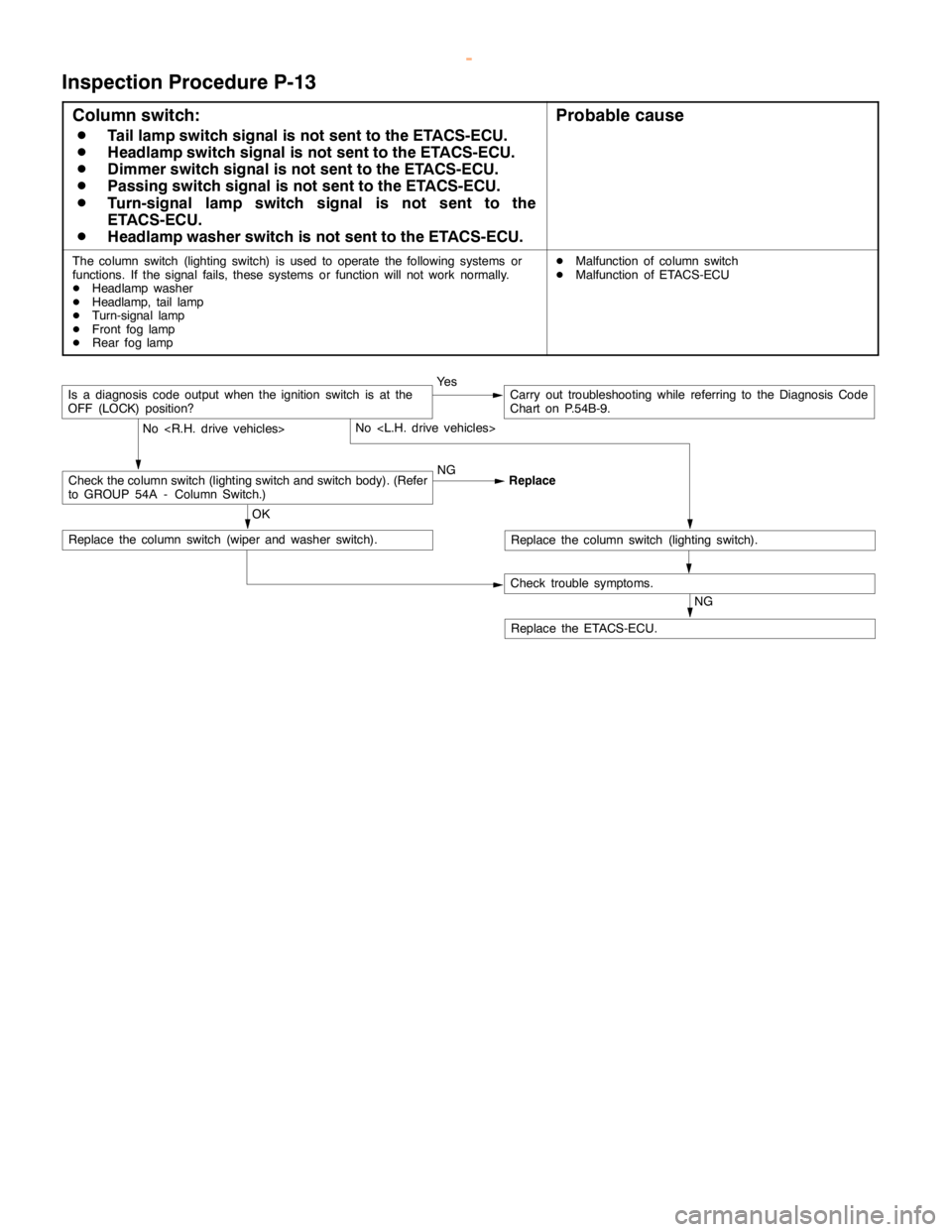
Inspection Procedure P-13
Column switch:
D
Tail lamp switch signal is not sent to the ETACS-ECU.
D
Headlamp switch signal is not sent to the ETACS-ECU.
D
Dimmer switch signal is not sent to the ETACS-ECU.
D
Passing switch signal is not sent to the ETACS-ECU.
D
Turn-signal lamp switch signal is not sent to the
ETACS-ECU.
D
Headlamp washer switch is not sent to the ETACS-ECU.
Probable cause
The column switch (lighting switch) is used to operate the following systems or
functions. If the signal fails, these systems or function will not work normally.
DHeadlamp washer
DHeadlamp, tail lamp
DTurn-signal lamp
DFront fog lamp
DRear foglampDMalfunction of column switch
DMalfunction of ETACS-ECU
NG
Replace the ETACS-ECU.
Ye sCarry out troubleshooting while referring to the Diagnosis Code
Chart on P.54B-9.
Check trouble symptoms.
No
Replace the column switch (lighting switch).
OK
Replace the column switch (wiper and washer switch).
No
Check the column switch (lighting switch and switch body). (Refer
to GROUP 54A - Column Switch.)NG
Replace
Is a diagnosis code output when the ignition switch is at the
OFF (LOCK) position?
www.WorkshopManuals.co.uk
Purchased from www.WorkshopManuals.co.uk
Page 1736 of 1839

SWS -Troubleshooting54B-50
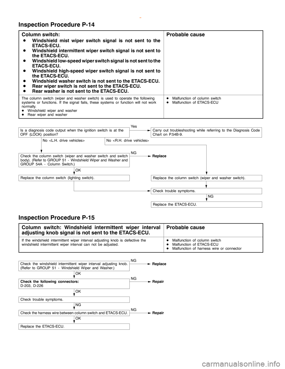
Inspection Procedure P-14
Column switch:
D
Windshield mist wiper switch signal is not sent to the
ETACS-ECU.
D
Windshield intermittent wiper switch signal is not sent to
the ETACS-ECU.
D
Windshield low-speed wiper switch signal is not sent to the
ETACS-ECU.
D
Windshield high-speed wiper switch signal is not sent to
the ETACS-ECU.
D
Windshield washer switch is not sent to the ETACS-ECU.
D
Rear wiper switch is not sent to the ETACS-ECU.
D
Rear washer is not sent to the ETACS-ECU.
Probable cause
The column switch (wiper and washer switch) is used to operate the following
systems or functions. If the signal fails, these systems or function will not work
normally.
DWindshield wiper and washer
DRear wiper and washerDMalfunction of column switch
DMalfunction of ETACS-ECU
NG
Replace the ETACS-ECU.
Ye sCarry out troubleshooting while referring to the Diagnosis Code
Chart on P.54B-9.
Check trouble symptoms.
No
Replace the column switch (wiper and washer switch).
OK
Replace the column switch (lighting switch).
No
Check the column switch (wiper and washer switch and switch
body). (Refer to GROUP 51 - Windshield Wiper and Washer and
GROUP 54A - Column Switch.)NG
Replace
Is a diagnosis code output when the ignition switch is at the
OFF (LOCK) position?
Inspection Procedure P-15
Column switch: Windshield intermittent wiper interval
adjusting knob signal is not sent to the ETACS-ECU.Probable cause
If the windshield intermittent wiper interval adjusting knob is defective the
windshield intermittent wiper interval can not be adjusted.DMalfunction of column switch
DMalfunction of ETACS-ECU
DMalfunction of harness wire or connector
OK
Replace the ETACS-ECU.
NG
Check the harness wire between column switch and ETACS-ECU.NG
Repair
OK
Check trouble symptoms.
OK
Check the following connectors:
D-203, D-226NG
Repair
Check the windshield intermittent wiper interval adjusting knob.
(Refer to GROUP 51 - Windshield Wiper and Washer.)NG
Replace
www.WorkshopManuals.co.uk
Purchased from www.WorkshopManuals.co.uk
Page 1741 of 1839

SWS -Troubleshooting54B-55
Terminal
No.Normal condition Checking requirements Check items
26Key reminder switch signal inputKey reminder switch: ON (Ignition key
removed)0V
27Hazard warning lamp switch signal
inputHazard warning lamp switch: ON0V
29Recognition line of daytime running
lamp (DRL)
31Data request signal outputAlways0 - 5 V (pulse
signal)
34Windshield intermittent wiper interval
adjusting knob signal inputIgnition switch: ACC,
Windshield intermittent wiper interval
adjusting knob: FAST®SLOW0®2.5 V
35Back-up lamp switch signal input
Shift lever: RSystem voltage
Inhibitor switch (reverse) signal input
Ignition switch: ON,
Selector lever: RSystem voltage
36Ignition key hole illumination lamp
outputWhen ignition key hole illumination
lamp is lighted2 V or less
37Diagnosis code or input signal check
outputWhen diagnosis code is output0 - 12 V (pulse
signal)
When input signal check is output0, 12 V (When input
pulse signal is
changed)
40Rear fog lamp relay outputWhen rear fog lamp is lighted2 V or less
53Front passenger’s and back door lock
key cylinder switch (LOCK) signal inputFront passenger’s or back door lock key
cylinder switch: LOCK0V
54Front passenger’s and back door lock
key cylinder switch (UNLOCK) signal
inputFront passenger’s or back door lock
switch: UNLOCK0V
55Driver’s door lock actuator switch
(LOCK) signal inputDriver’s door lock actuator switch:
LOCK0V
56Driver’s door lock actuator switch
(UNLOCK) signal inputDriver’s door lock actuator switch:
UNLCOK0V
www.WorkshopManuals.co.uk
Purchased from www.WorkshopManuals.co.uk
Page 1820 of 1839

HEATER, AIR CONDITIONER AND VENTILATION -Troubleshooting
DATA LIST REFERENCE TABLE
Item No.Check itemInspection contents
11Inside air temperature sensorIgnition switch: ONInside air temperature and tempera-
ture displayed on the MUT-IIare
identical.
13Outside air temperature sen-
sorIgnition switch: ONOutside air temperature and tem-
perature displayed on the MUT-II
are identical.
15Heater water temperature
sensorIgnition switch: ONHeater core surface temperature
and temperature displayed on the
MUT-IIare identical.
21Air thermo sensorIgnition switch: ONEvaporator outlet temperature and
temperature displayed on the MUT-
IIare identical.
25Photo sensorIgnition switch: ONAmount of incident light is propor-
tional to voltage displayed on the
MUT-II.
31Potentiometer for the air mix
damperIgnition switch: ON
Damper position: MAX HOTOpening angle: Approximately
100%
Ignition switch: ON
Damper position: MAX COOLOpening angle: Approximately 0%
32Potentiometer for the air
outlet changeover damperIgnition switch: ON
Damper position: FACEOpening angle: Approximately 0%
Ignition switch: ON
Damper position:FOOTOpening angle: Approximately 60%
Ignition switch: ON
Damper position: FOOT/DEFOpening angle: Approximately 80%
Ignition switch: ON
Damper position: DEFOpening angle: Approximately
100%
ACTUATOR TEST TABLE
Item No.Check itemDrive Contents
01Blower motorStopped
02Low speed
03Medium speed
04High speed
05Electric motor for the air mix damperOpening angle: Approximately 0%
06Opening angle: Approximately 50%
07Opening angle: Approximately 100%
08Electric motor for the air outlet changeoverFACE
09damperFOOT
10DEF
11Compressor ON/OFFOFF
12ON
13Inside/outside air changeover damper motorOutside air
14Inside air
www.WorkshopManuals.co.uk
Purchased from www.WorkshopManuals.co.uk
Page 1822 of 1839

HEATER, AIR CONDITIONER AND VENTILATION -Troubleshooting
Termi-
nal No.Normal condition Check conditions Check item
15Rear defoggerRear defogger: OFFSystem voltage
Rear defogger: ON1.5 V or less
16Multi center display unit communication
lineIgnition switch: ONHi: 4 - 5 V
Lo: 0 - 1 V
17Multi center display unit communication
lineIgnition switch: ONHi: 4 - 5 V
Lo: 0 - 1 V
18Multi center display unit communication
line shieldAt all times0V
19Diagnosis outputIgnition switch: ONA voltmeter needle
fluctuates between 0
and 12 V.
20Input from A/C compressor relayWhen the A/C is off.0V
When the A/C is in operation
(When compressor is operating)System voltage
21Power supply to potentiometerAt all times5V
22Input from outside air temperature
sensorSensor temperature: 25
_C (1.7 kW)1.9 V
23Input from heater water temperature
sensorSensor temperature: 25
_C(5kW)2.8 V
24Input from potentiometer for air mix
damperWhen the damper flap is moving to the
MAX HOT position.0.7 - 1.3 V
25Power supply to illuminationLighting switch: ONSystem voltage
26Power supply to ignition switch (IG2)Ignition switch: ONSystem voltage
27Power supply to ignition switch (ACC)Ignition switch: ACCSystem voltage
28Backup power supplyAt all timesSystem voltage
29Earth to sensor and potentiometerAt all times0V
30Input from air thermo sensorSensor temperature: 25
_C (1.5 kW)2.2 V
31Photo sensor (+)During 800 kcal/m2-h1V
32Input from potentiometer for the air
outlet changeover damperWhen the damper flap is moving to the
DEF position.0.7 - 1.3 V
33Diagnosis inputIgnition switch: ON0V
34Compressor lock signal (ignition signal)Engine speed: 3 000 r/min0.3 - 3.0
35Illumination earthAt all timesContinuity
36EarthAt all timesContinuity
CHECK AT ENGINE-A/T-ECU OR ENGINE-ECU TERMINALS
Refer to GROUP 13A – Troubleshooting
www.WorkshopManuals.co.uk
Purchased from www.WorkshopManuals.co.uk