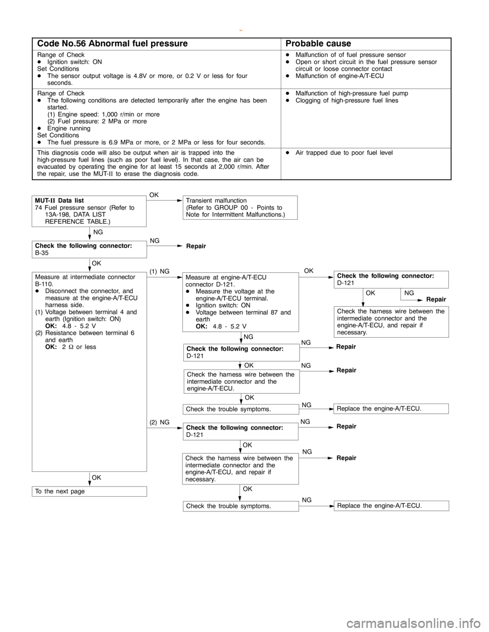
2000 MITSUBISHI MONTERO fuel pump
[x] Cancel search: fuel pumpPage 299 of 1839
GDI -Troubleshooting
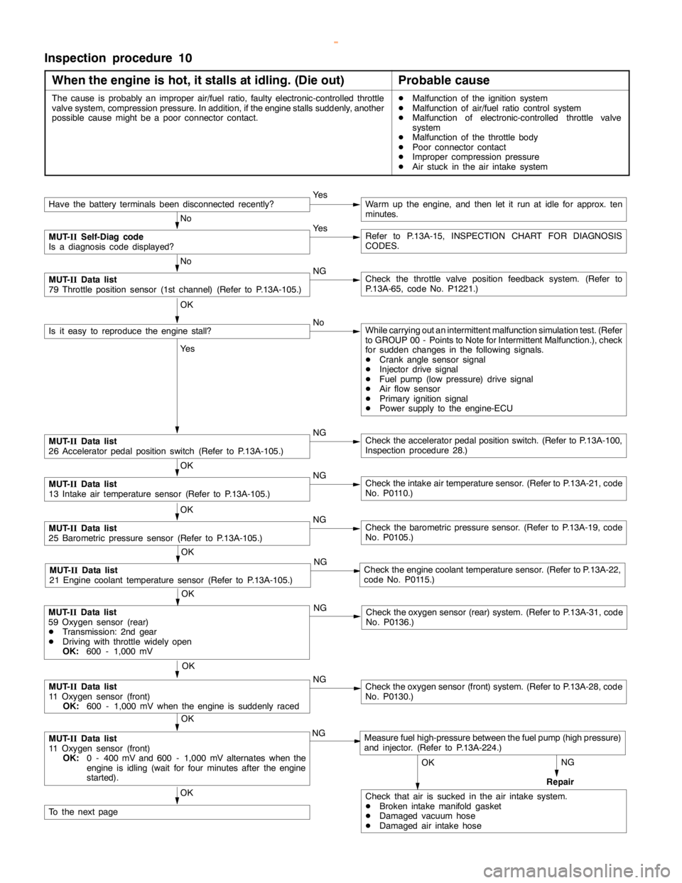
Inspection procedure 10
When the engine is hot, it stalls at idling. (Die out)
Probable cause
The cause is probably an improper air/fuel ratio, faulty electronic-controlled throttle
valve system, compression pressure. In addition, if theenginestalls suddenly, another
possible causemight be a poorconnector contact.DMalfunction of the ignition system
DMalfunction of air/fuel ratio control system
DMalfunction of electronic-controlled throttle valve
system
DMalfunction of the throttle body
DPoor connector contact
DImproper compression pressure
DAir stuck in the air intake system
NG
Repair
Have the battery terminalsbeen disconnectedrecently?Ye sWarm up the engine, and then let it run at idle for approx. ten
minutes.
No
MUT-
IISelf-Diag code
Is a diagnosis code displayed?Ye sRefer to P.13A-15, INSPECTION CHART FOR DIAGNOSIS
CODES.
No
MUT-
IIData list
79 Throttle position sensor (1st channel) (Refer to P.13A-105.)NGCheck the throttle valve position feedback system. (Refer to
P.13A-65, code No. P1221.)
OK
Is it easy to reproduce theengine stall?NoWhile carrying out an intermittent malfunction simulation test. (Refer
to GROUP 00 - Points to Note for Intermittent Malfunction.), check
for sudden changes in the following signals.
DCrankanglesensor signal
DInjector drive signal
DFuel pump(low pressure) drive signal
DAir flow sensor
DPrimary ignition signal
DPower supply to the engine-ECU
Ye s
MUT-
IIData list
26 Acceleratorpedal positionswitch (Refer to P.13A-105.)NGCheck the acceleratorpedal positionswitch. (Refer to P.13A-100,
Inspection procedure 28.)
OK
MUT-
IIData list
13 Intake air temperature sensor (Refer to P.13A-105.)NGCheck the intake air temperature sensor. (Refer to P.13A-21, code
No. P0110.)
OK
MUT-
IIData list
25 Barometric pressure sensor (Refer to P.13A-105.)NGCheck the barometric pressure sensor. (Refer to P.13A-19, code
No. P0105.)
OK
MUT-
IIData list
21 Engine coolant temperature sensor (Refer to P.13A-105.)NGCheck theengine coolant temperaturesensor. (Refer to P.13A-22,
code No. P0115.)
OK
MUT-
IIData list
11 Oxygen sensor (front)
OK:
600 - 1,000 mV when theengine is suddenlyracedNGCheck the oxygen sensor (front) system. (Refer to P.13A-28, code
No. P0130.)
OK
MUT-
IIData list
11 Oxygen sensor (front)
OK:
0 - 400 mV and 600 - 1,000 mV alternates when the
engine is idling(wait for four minutes after theengine
started).NGMeasure fuel high-pressure between the fuel pump (highpressure)
and injector. (Refer to P.13A-224.)
OK
Check that air is sucked in the air intake system.
DBroken intakemanifoldgasket
DDamaged vacuum hose
DDamaged air intake hoseOK
To the nextpage
OK
MUT-
IIData list
59 Oxygen sensor (rear)
DTransmission: 2nd gear
DDriving with throttle widelyopen
OK:
600 - 1,000 mVNGCheck the oxygen sensor (rear) system. (Refer to P.13A-31, code
No. P0136.)
www.WorkshopManuals.co.uk
Purchased from www.WorkshopManuals.co.uk
Page 303 of 1839
GDI -Troubleshooting
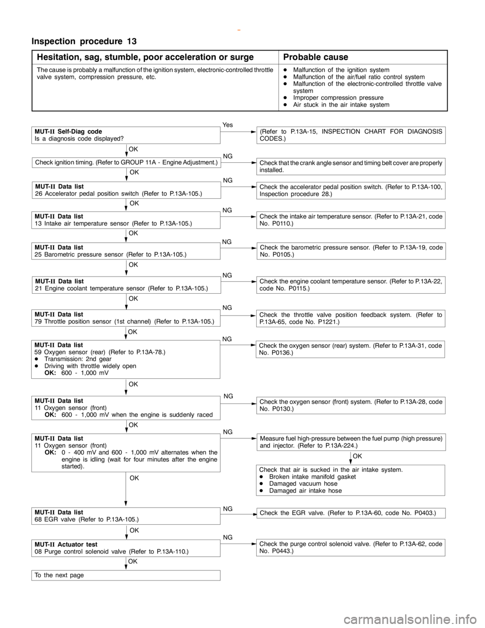
Inspection procedure 13
Hesitation, sag, stumble, poor acceleration or surge
Probable cause
The cause is probably a malfunction of the ignition system, electronic-controlled throttle
valve system, compression pressure, etc.DMalfunction of the ignition system
DMalfunction of the air/fuel ratio control system
DMalfunction of the electronic-controlled throttle valve
system
DImproper compression pressure
DAir stuck in the air intake system
MUT-
IISelf-Diag code
Is a diagnosis code displayed?Ye s(Refer to P.13A-15, INSPECTION CHART FOR DIAGNOSIS
CODES.)
OK
Check ignition timing. (Refer to GROUP 11A - Engine Adjustment.)NGCheck that the crankanglesensor andtiming beltcover are properly
installed.
OK
NG
Check the acceleratorpedal positionswitch. (Refer to P.13A-100,
Inspection procedure 28.)
OK
MUT-
IIData list
13 Intake air temperature sensor (Refer to P.13A-105.)NGCheck the intake air temperature sensor. (Refer to P.13A-21, code
No. P0110.)
OK
MUT-
IIData list
25 Barometric pressure sensor (Refer to P.13A-105.)NGCheck the barometric pressure sensor. (Refer to P.13A-19, code
No. P0105.)
OK
MUT-
IIData list
21 Engine coolant temperature sensor (Refer to P.13A-105.)NGCheck theengine coolant temperaturesensor. (Refer to P.13A-22,
code No. P0115.)
OK
MUT-
IIData list
79 Throttle position sensor (1st channel) (Refer to P.13A-105.)NGCheck the throttle valve position feedback system. (Refer to
P.13A-65, code No. P1221.)
OK
MUT-
IIData list
11 Oxygen sensor (front)
OK:
0 - 400 mV and 600 - 1,000 mV alternates when the
engine is idling(wait for four minutes after theengine
started).NGMeasure fuel high-pressure between the fuel pump (highpressure)
and injector. (Refer to P.13A-224.)
OK
MUT-
IIData list
11 Oxygen sensor (front)
OK:
600 - 1,000 mV when theengine is suddenlyracedNGCheck the oxygen sensor (front) system. (Refer to P.13A-28, code
No. P0130.)
OK
Check that air is sucked in the air intake system.
DBroken intake manifold gasket
DDamaged vacuum hose
DDamaged air intake hose
OK
MUT-
IIData list
68 EGR valve (Refer to P.13A-105.)NGCheck the EGR valve. (Refer to P.13A-60, code No. P0403.)
OK
MUT-
IIActuator test
08 Purge control solenoid valve (Refer to P.13A-110.)NGCheck the purge control solenoid valve. (Refer to P.13A-62, code
No. P0443.)
OK
To the nextpage
OK
MUT-
IIData list
59 Oxygen sensor (rear) (Refer to P.13A-78.)
DTransmission: 2nd gear
DDriving with throttle widelyopen
OK:
600 - 1,000 mVNGCheck the oxygen sensor (rear) system. (Refer to P.13A-31, code
No. P0136.)
MUT-
IIData list
26 Acceleratorpedal positionswitch (Refer to P.13A-105.)
www.WorkshopManuals.co.uk
Purchased from www.WorkshopManuals.co.uk
Page 304 of 1839
GDI -Troubleshooting
From the previouspage
OK
Measure high fuelpressure between the fuelpump (highpressure)
and injector. (Refer to P.13A-224.)NG
Repair
OK
Check ignition coil spark for each cylinder.
(1) Remove the ignition coil.
(2) Install a new sparkplug to the removed ignitioncoil.
(3) Disconnect the injector intermediate connector.
Caution
Never touch the connector terminal as approx. 100 V is
applied to the injector, or you are seriously injured.
(4) Earth the sparkplug electrodesecurely.
(5) Check that the sparkplug igniteswhen theengine iscranked.NGReplace the ignition coil.
OK
Check all the following items:
DSparkplug
DEGR system
DCompression pressure
DClogged fuel filter, fuel lineNGCheck trouble symptom.
Replace the injector.
OK
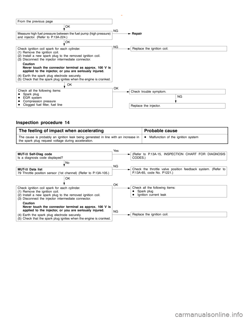
Inspection procedure 14
The feeling of impact when accelerating
Probable cause
The cause is probably an ignition leakbeing generated in linewith an increase in
the sparkplug request voltage during acceleration.DMalfunction of the ignition system
NGReplace the ignition coil.
MUT-
IISelf-Diag code
Is a diagnosis code displayed?Ye s(Refer to P.13A-15, INSPECTION CHART FOR DIAGNOSIS
CODES.)
No
MUT-
IIData list
79 Throttle position sensor (1st channel) (Refer to P.13A-105.)NGCheck the throttle valve position feedback system. (Refer to
P.13A-65, code No. P1221.)
OK
Check ignition coil spark for each cylinder.
(1) Remove the ignition coil.
(2) Install a new sparkplug to the removed ignitioncoil.
(3) Disconnect the injector intermediate connector.
Caution
Never touch the connector terminal as approx. 100 V is
applied to the injector, or you are seriously injured.
(4) Earth the sparkplug electrodesecurely.
(5) Check that the sparkplug igniteswhen theengine iscranked.OKCheck all the following items:
DSparkplug
DIgnition current leak
www.WorkshopManuals.co.uk
Purchased from www.WorkshopManuals.co.uk
Page 306 of 1839
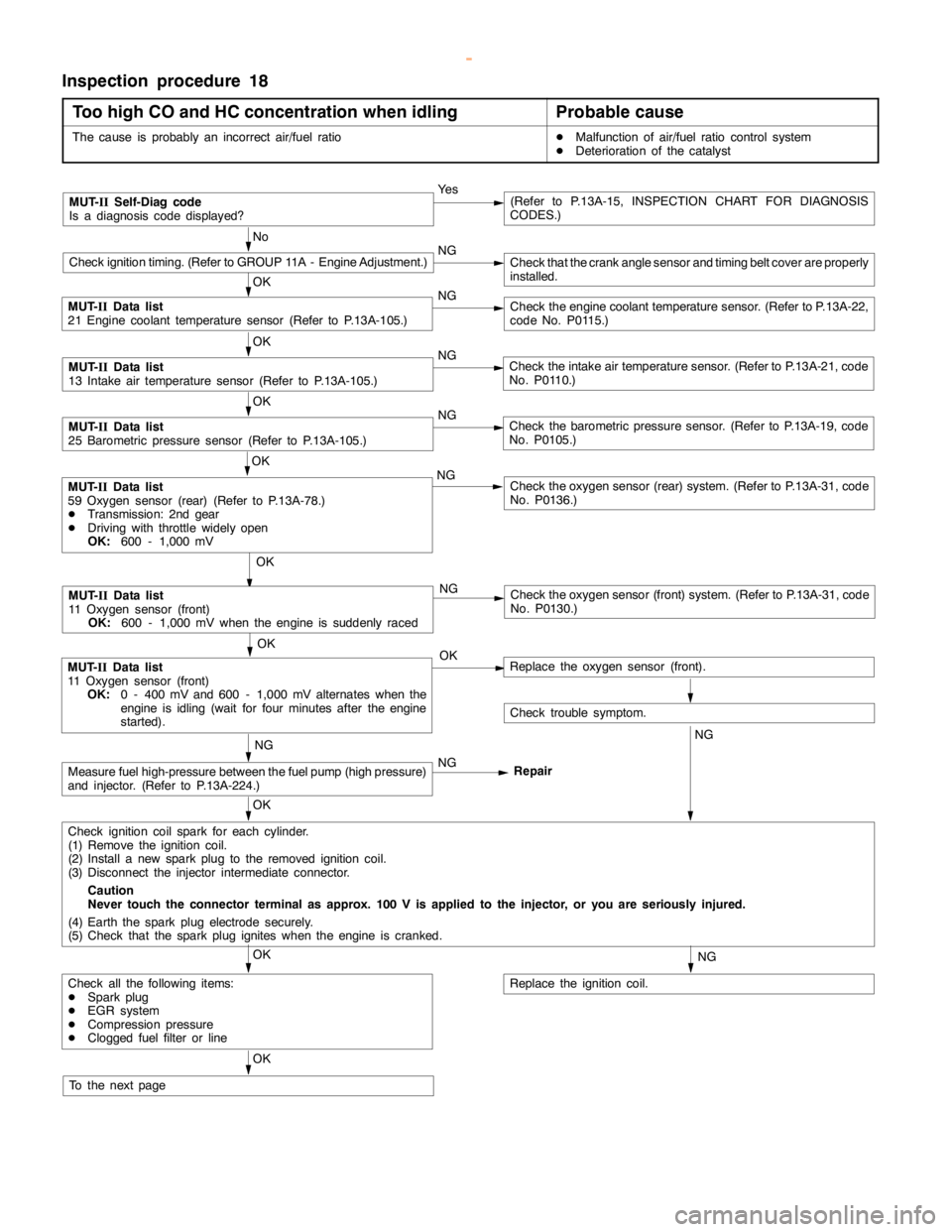
GDI -Troubleshooting
Inspection procedure 18
Too high CO and HC concentration when idling
Probable cause
The cause is probably an incorrect air/fuel ratioDMalfunction of air/fuel ratio control system
DDeterioration of the catalyst
MUT-
IISelf-Diag code
Is a diagnosis code displayed?Ye s(Refer to P.13A-15, INSPECTION CHART FOR DIAGNOSIS
CODES.)
No
Check ignition timing. (Refer to GROUP 11A - Engine Adjustment.)NGCheck that the crankanglesensor andtiming beltcover are properly
installed.
OK
MUT-
IIData list
21 Engine coolant temperature sensor (Refer to P.13A-105.)NGCheck theengine coolant temperaturesensor. (Refer to P.13A-22,
code No. P0115.)
OK
MUT-
IIData list
13 Intake air temperature sensor (Refer to P.13A-105.)NGCheck the intake air temperature sensor. (Refer to P.13A-21, code
No. P0110.)
OK
MUT-
IIData list
25 Barometric pressure sensor (Refer to P.13A-105.)NGCheck the barometric pressure sensor. (Refer to P.13A-19, code
No. P0105.)
OK
NG
Check the oxygen sensor (front) system. (Refer to P.13A-31, code
No. P0130.)
OK
MUT-
IIData list
11 Oxygen sensor (front)
OK:
0 - 400 mV and 600 - 1,000 mV alternates when the
engine is idling(wait for four minutes after theengine
started).OKReplace the oxygen sensor (front).
Check trouble symptom.
NGNG
Measure fuel high-pressure between the fuel pump (highpressure)
and injector. (Refer to P.13A-224.)NG
Repair
OK
Check ignition coil spark for each cylinder.
(1) Remove the ignition coil.
(2) Install a new sparkplug to the removed ignitioncoil.
(3) Disconnect the injector intermediate connector.
Caution
Never touch the connector terminal as approx. 100 V is applied to the injector, or you are seriously injured.
(4) Earth the sparkplug electrodesecurely.
(5) Check that the sparkplug igniteswhen theengine iscranked.
NG
Replace the ignition coil.
OK
Check all the following items:
DSparkplug
DEGR system
DCompression pressure
DClogged fuel filter or line
OK
To the nextpage
OK
MUT-
IIData list
59 Oxygen sensor (rear) (Refer to P.13A-78.)
DTransmission: 2nd gear
DDriving with throttle widelyopen
OK:
600 - 1,000 mVNGCheck the oxygen sensor (rear) system. (Refer to P.13A-31, code
No. P0136.)
MUT-
IIData list
11 Oxygen sensor (front)
OK:
600 - 1,000 mV when theengine is suddenlyraced
www.WorkshopManuals.co.uk
Purchased from www.WorkshopManuals.co.uk
Page 315 of 1839
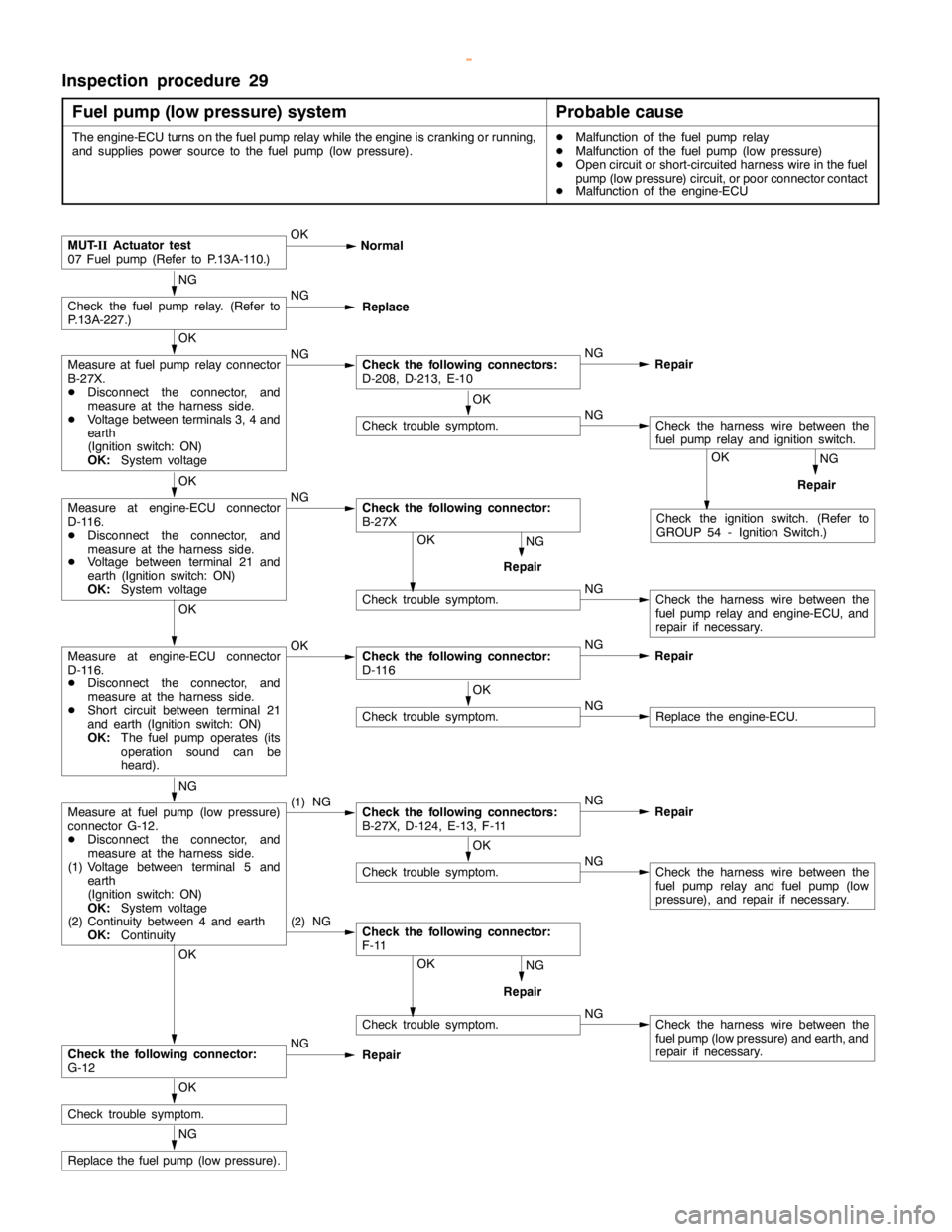
GDI -Troubleshooting
Inspection procedure 29
Fuel pump (low pressure) system
Probable cause
The engine-ECU turns on the fuelpumprelay while theengine iscranking or running,
and supplies power source to the fuelpump(low pressure).DMalfunction of the fuel pumprelay
DMalfunction of the fuel pump(low pressure)
DOpen circuit or short-circuited harness wire in the fuel
pump(low pressure) circuit, or poor connector contact
DMalfunction of the engine-ECU
Check trouble symptom.NGCheck the harness wire between the
fuel pump(low pressure) and earth, and
repair if necessary.
NG
RepairOK
Check trouble symptom.NGCheck the harness wire between the
fuel pumprelay and engine-ECU, and
repair if necessary.
NG
RepairOK
NG
RepairOK
Check the ignition switch. (Refer to
GROUP 54 - Ignition Switch.)
(2) NGCheck the following connector:
F-11
MUT-
IIActuator test
07 Fuel pump(Refer to P.13A-110.)OK
Normal
NG
Check the fuelpumprelay. (Refer to
P.13A-227.)NG
Replace
OK
Measure at fuel pumprelay connector
B-27X.
DDisconnect the connector, and
measure at the harness side.
DVoltage between terminals 3, 4 and
earth
(Ignition switch: ON)
OK:
System voltageNGCheck the following connectors:
D-208, D-213, E-10NG
Repair
OK
Check trouble symptom.NGCheck the harness wire between the
fuel pumprelay and ignition switch.
OK
Measure at engine-ECU connector
D-116.
DDisconnect the connector, and
measure at the harness side.
DVoltage between terminal 21 and
earth (Ignition switch: ON)
OK:
System voltageNGCheck the following connector:
B-27X
OK
Measure at engine-ECU connector
D-116.
DDisconnect the connector, and
measure at the harness side.
DShort circuit between terminal 21
and earth (Ignition switch: ON)
OK:
The fuel pump operates(its
operation sound can be
heard).OKCheck the following connector:
D-116NG
Repair
OK
Check trouble symptom.NGReplace the engine-ECU.
NG
Measure at fuel pump(low pressure)
connector G-12.
DDisconnect the connector, and
measure at the harness side.
(1) Voltage between terminal 5 and
earth
(Ignition switch: ON)
OK:
System voltage
(2) Continuity between 4 and earth
OK:
Continuity(1) NGCheck the following connectors:
B-27X, D-124, E-13, F-11NG
Repair
OK
Check trouble symptom.NGCheck the harness wire between the
fuel pumprelay and fuelpump(low
pressure), and repair if necessary.
OK
Check the following connector:
G-12NG
Repair
OK
Check trouble symptom.
NG
Replace the fuel pump(low pressure).
www.WorkshopManuals.co.uk
Purchased from www.WorkshopManuals.co.uk
Page 324 of 1839

GDI -Troubleshooting
ACTUATOR TEST REFERENCE TABLE
Item
No.Inspection
itemDrive contentsInspection contentsNormal conditionInspection
procedure
No.Reference
page
01InjectorsCut fuel to No. 1
injectorEngine:
After havingIdling condition
becomes differentCode No.
P020113A-38
02Cut fuel to No. 2
injector
warmed up/Engine
is idling
(Cut the fuel supply(becomes unsta-
ble).
Code No.
P020213A-40
03Cut fuel to No. 3
injectorto each injector in
turn and check
cylinders whichCode No.
P020313A-42
04Cut fuel to No. 4
injectordon’t affect idling.)Code No.
P020413A-44
05Cut fuel to No. 5
injectorCode No.
P020513A-46
06Cut fuel to No. 6
injectorCode No.
P020613A-48
07Fuel pump
(low pressure)Fuel pump
operates and
fuel is recirculated.Ignition switch: ONSound of opera-
tion is heard.Procedure
No. 2913A-101
08Purge
control
solenoid valveSolenoid valve
turns from OFF to
ON.Ignition switch: ONSound of opera-
tion can be heard
when solenoid
valve is
driven.Code No.
P044313A-62
17Basic ignition
timingSet the engine-
ECU to ignition
timing adjustment
modeIdling after engine
warm up5_BTDC--
21Condenser fanDrive the fan motorIgnition switch: ONThe fan motor
operatesProcedure
No.2113A-95
34Electronic-
controlled
throttle valve
systemStop the throttle
control servo.Ignition switch: ONThrottle valve is
opened slightly.Code No.
P122013A-64
www.WorkshopManuals.co.uk
Purchased from www.WorkshopManuals.co.uk
Page 326 of 1839

GDI -Troubleshooting
Terminal
No.Normal condition Check requirements (engine condition) Check item
16Purge control solenoid valveDEngine cool-Engine: stoppedSystem voltage
ant tempera-
ture:
80 - 95_C
DIgnition
switch: ON
Engine: Start the
engine, and then
increase engine
speed up to 3,500
r/min.Voltage decreases.
18Condenser fan relayCondenser fan is not operating.System voltage
Condenser fan is operating.0-3V
20Fuel pump relayIgnition switch:Engine: stoppedSystem voltage
ON
Engine: idling0-3V
21A/C relayDEngine: idlingSystem voltage, or changes
DA/C switch: OFF®ON
(Compressor is operating)from momentarily 6 V or
more to 0®3V
31Engine warning lampIgnition switch: OFF®ON0-3V®System voltage
(after several seconds)
41Sensor power supplyIgnition switch: ON4.5 - 5.5 V
42Power supply to accelerator
pedal position sensor (1st
channel)Ignition switch: ON4.5 - 5.5 V
43Crank angle sensorEngine: Cranking0.4 - 4.0 V
Engine: Idling1.5 - 2.5 V
44Engine coolant temperature
sensorIgnition switch:
ONEngine coolant
temperature: 0_C3.2 - 3.5 V
Engine coolant
temperature:
20_C2.3 - 2.9 V
Engine coolant
temperature:
40_C1.5 - 2.1 V
Engine coolant
temperature:
80_C0.4 - 1.0 V
45Engine ignition signalEngine: 3,000 r/min0.3 - 3.0 V
www.WorkshopManuals.co.uk
Purchased from www.WorkshopManuals.co.uk
Page 365 of 1839
