Page 434 of 1111

DISASSEMBLY
1. PLACE HYDRAULIC BRAKE BOOSTER IN VISE
Using SST,")
BR0YV±02
F06048
SST
SST
F06961
F01657Pin
± BRAKEHYDRAULIC BRAKE BOOSTER
BR±51
2159 Author�: Date�:
2000 LEXUS GS300/GS400 (RM718U)
DISASSEMBLY
1. PLACE HYDRAULIC BRAKE BOOSTER IN VISE
Using SST, set the hydraulic brake booster in vise.
SST 09630±00014 (09631±00142),
09950±60010 (09951±00180, 09951±00190)
2. REMOVE RESERVOIR AND GROMMETS
(a) Remove the reservoir cap.
(b) Remove the 3 set screws and pull out the reservoir.
Torque: 1.7 N´m (17.5 kgf´cm, 15.2 in.´lbf)
(c) Remove the 3 grommets.
3. REMOVE CYLINDER BOOT
4. REMOVE OIL PRESSURE SENSOR
Using 30 mm deeper socket wrench and remove the oil pres-
sure sensor, spacer and O±ring.
Torque: 81 N´m (830 kgf´cm, 60 ft´lbf)
5. REMOVE PISTONS
(a) Pressing the piston in with a screwdriver, use a pin or an
equivalent to push the snap ring from the hole in the body
then remove it with another screwdriver.
(b) Remove the No. 1 and No. 2 piston, pulling straight out,
not at an angle.
NOTICE:
�If pulled out and installed at an angle, there is a possi-
bility that the cylinder bore could be damaged.
�At the time of reassembly, be careful not to damage
the rubber lips on the pistons.
6. DISCONNECT ACTUATOR HOSE
7. REMOVE 3 BOLTS, 2 HANGERS AND CLAMP
Page 487 of 1111
B01985
Water Bypass Outlet
� O±Ring
Engine Wire
Water
Pump
Connector Bracket
Idler PulleyGasket
Timing Belt GuideNo.2 Water Bypass Pipe
Drain Hose
Timing Belt Tensioner
Timing Belt
Drive Belt TensionerOil Filler Cap
No.3 Timing Belt Cover
No.1 Water
Bypass Pipe
� Gasket
Crankshaft PulleyDust Boot
x 5 Thermostat
� O±Ring
� O±Ring
No.2 Timing Belt Cover
Gasket
No.1 Timing Belt Cover
� Gasket
Water Inlet
x 6
35 (350, 26)
21 (210, 15)
21 (210, 15)
27 (270, 20)�
N´m (kgf´cm, ft´lbf) : Specified torque
� Non±reusable part
� Precoated part
330 (3,300, 243)
Clamp Bracket
Crankshaft Position
Sensor Connector
Gasket
CO±4
± COOLING (2JZ±GE)WATER PUMP
1542 Author�: Date�:
2000 LEXUS GS300/GS400 (RM718U)
Page 518 of 1111

A11128
Accelerator Pedal Position Sensor Connector
Throttle Control Motor Connector
Throttle Body and Intake Air Connector Assembly
Water Bypass HoseVSV Connector
for EVAP
EVAP Hose
� Gasket Air Assist Hose Engine Wire
Oil Filler Cap
No.3 Timing Belt Cover
Gasket
No.2 Timing Belt Cover
GasketThrottle
Position
Sensor
Connector
Vacuum Hose
(from Actuator for ACIS)
Water Bypass Hose
Engine Wire Protector
High±Tension
Cord w/ Clamp
No.1 Cylinder
Head Cover
Gasket
Timing Belt
x 6
Timing Belt Guide
Gasket
x 5 No.1 Timing Belt Cover
Crankshaft
Pulley
21 (210, 15)
Drive Belt Tensioner
330 (3,300, 243)
Camshaft
Timing Pulley
(VVT±i Pulley)81 (810, 60)
Straight
Screw Plug
15 (150, 11)Seal Washer
Camshaft
Timing Oil
Control Valve
Camshaft Timing
Oil Control
Valve Connector� Gasket
Oil Control Valve Filter
� O±Ring
No.1 Oil PipeUnion Bolt
55 (550, 41)
Idler Pulley
Crankshaft Timing Pulley
Timing Belt Plate
Timing Belt Tensioner
N´m (kgf´cm, ft´lbf) : Specified torque
35 (350, 26)�
8.0 (80, 71 in.´lbf)
27 (270, 20)
� Non±reusable part
� Precoated part
Dust Boot
Engine Wire ClampPCV Hose
Vacuum Hose
(from No.2
Vacuum Pipe)
± ENGINE MECHANICAL (2JZ±GE)TIMING BELT
EM±15
1369 Author�: Date�:
2000 LEXUS GS300/GS400 (RM718U)
Page 521 of 1111
TIMING BELT
1372 Author�: Date�:
2000 LEXUS GS300/GS400 (RM718U)
(")
P11002
A11127
SST
A11126
5 mm
Hexagon
Wrench
A02662
Gasket
Union Bolt
Oil Control
Valve Filter
EM±18
± ENGINE MECHANICAL (2JZ±GE)TIMING BELT
1372 Author�: Date�:
2000 LEXUS GS300/GS400 (RM718U)
(a) Alternately loosen the 2 bolts, and remove them, the ten-
sioner and dust boot.
(b) Disconnect the timing belt from the camshaft timing pul-
leys.
12. REMOVE EXHAUST CAMSHAFT TIMING PULLEY
Using SST, remove the bolt and timing pulley.
SST 09960±10010 (09962±01000, 09963±01000)
13. REMOVE ENGINE COVER
Remove the 4 nuts and engine cover.
14. REMOVE THROTTLE BODY AND INTAKE AIR
CONNECTOR ASSEMBLY (See page EM±5)
15. REMOVE NO.1 CYLINDER HEAD COVER
(a) Using a 5 mm hexagon wrench, remove the bolts, and dis-
connect the engine wire protector from the No.2 cylinder
head cover.
(b) Remove the nut, and disconnect the engine wire protec-
tor from the intake manifold.
(c) Remove the 2 bolts, and disconnect the high±tension
cords with the clamp from the No.2 cylinder head.
(d) Remove the 6 bolts, 2 nuts, No.1 cylinder head cover and
gasket.
16. REMOVE CAMSHAFT TIMING OIL CONTROL VALVE
(See page SF±43)
17. DISCONNECT NO.1 OIL PIPE
Remove the bolt, union bolt, oil control valve filter and 2 gas-
kets, and disconnect the No.1 oil pipe from the No.3 camshaft
bearing cap.
Page 529 of 1111
TIMING BELT
1380 Author�: Date�:
2000 LEXUS GS300/GS400 (RM718U)
(d) Using SST, align the")
A02821
AlignSST
Turn
A02653
A02654
Z02446
1.5 mm
Hexagon
Wrench
P04459
EM±26
± ENGINE MECHANICAL (2JZ±GE)TIMING BELT
1380 Author�: Date�:
2000 LEXUS GS300/GS400 (RM718U)
(d) Using SST, align the dot mark on the camshaft timing tim-
ing pulley with the timing mark of the No.4 timing belt cov-
er.
SST 09960±10010 (09962±01000, 09963±01000)
14. CONNECT TIMING BELT TO CAMSHAFT TIMING
PULLEYS
HINT:
When re±using timing belt:
�Check that the matchmark on the timing belt matches the
end of the No.1 timing belt cover.
If the matchmark does not align, shift the meshing of the
timing belt and crankshaft timing pulley until they align.
�Align the matchmarks of the timing belt and camshaft tim-
ing pulleys.
(a) Remove any oil or water on the camshaft timing pulley,
and keep it clean.
(b) Install the timing belt, checking the tension between the
crankshaft timing pulley and intake camshaft timing
pulley.
15. SET TIMING BELT TENSIONER
(a) Using a press, slowly press in the push rod using 981 ±
9,807 N (100 ± 1,000 kgf, 220 ± 2,205 lbf) of force.
(b) Align the holes of the push rod and housing, pass a 1.5
mm hexagon wrench through the holes to keep the push
rod retracted.
(c) Release the press.
(d) Install the dust boot onto the tensioner.
Page 533 of 1111
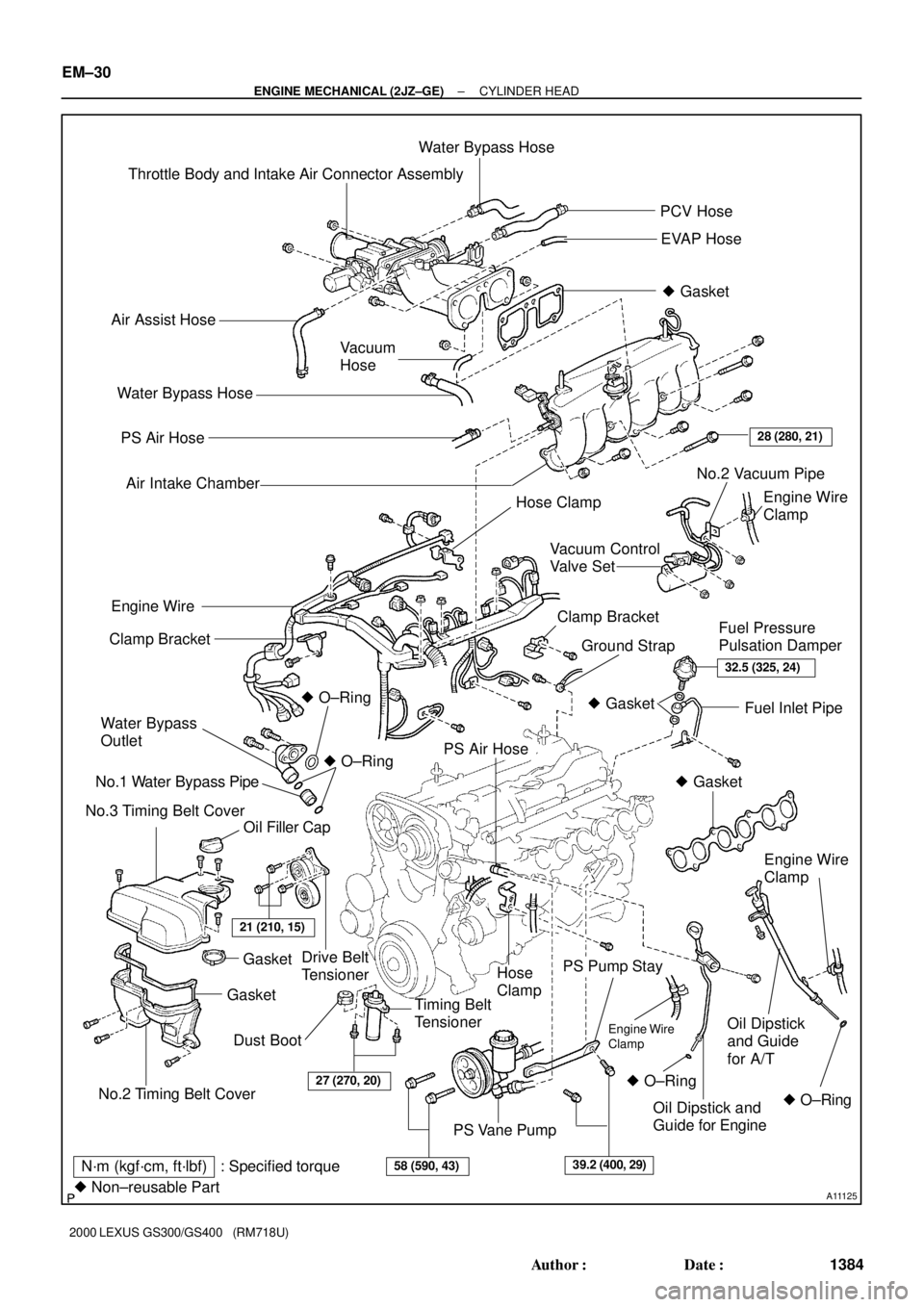
A11125
Throttle Body and Intake Air Connector AssemblyWater Bypass Hose
PCV Hose
EVAP Hose
� Gasket
Air Assist Hose
Vacuum
Hose
PS Air Hose
Air Intake Chamber
Engine Wire
Clamp
Drive Belt
TensionerClamp Bracket
Ground StrapFuel Pressure
Pulsation Damper Clamp Bracket
Water Bypass
Outlet
No.1 Water Bypass Pipe
No.3 Timing Belt Cover� O±Ring
Oil Filler CapFuel Inlet Pipe
PS Air Hose
Hose
Clamp
Timing Belt
Tensioner
PS Pump Stay
Oil Dipstick
and Guide
for A/T
PS Vane Pump Water Bypass Hose
28 (280, 21)
Engine Wire
� O±Ring
No.2 Timing Belt Cover
GasketGasket
21 (210, 15)
32.5 (325, 24)
� Gasket
� Gasket
Engine Wire
Clamp
� O±Ring � O±RingOil Dipstick and
Guide for Engine
27 (270, 20)
58 (590, 43)39.2 (400, 29)N´m (kgf´cm, ft´lbf) : Specified torque
� Non±reusable Part
Dust BootEngine Wire
Clamp
No.2 Vacuum Pipe
Hose Clamp
Vacuum Control
Valve Set
EM±30
± ENGINE MECHANICAL (2JZ±GE)CYLINDER HEAD
1384 Author�: Date�:
2000 LEXUS GS300/GS400 (RM718U)
Page 610 of 1111

IN00U±35
N17080
Filler Cap
Float
Reservoir Tank
� Grommet
Clip
Slotted Spring Pin
: Specified torque
� Non±reusable partCylinder
Piston
Push Rod
Washer
Snap Ring
Boot
� Gasket
Lock Nut
Clevis Pin
Clevis
N´m (kgf´cm, ft´lbf)
12 (120, 9)
15 (155, 11)
± INTRODUCTIONHOW TO USE THIS MANUAL
IN±1
1 Author�: Date�:
2000 LEXUS GS300/GS400 (RM718U)
HOW TO USE THIS MANUAL
GENERAL INFORMATION
1. INDEX
An INDEX is provided on the first page of each section to guide you to the item to be repaired. To assist you
in finding your way through the manual, the section title and major heading are given at the top of every page.
2. PRECAUTION
At the beginning of each section, a PRECAUTION is given that pertains to all repair operations contained
in that section.
Read these precautions before starting any repair task.
3. TROUBLESHOOTING
TROUBLESHOOTING tables are included for each system to help you diagnose the problem and find the
cause. The fundamentals of how to proceed with troubleshooting are described on page IN±21.
Be sure to read this before performing troubleshooting.
4. PREPARATION
Preparation lists the SST (Special Service Tools), recommended tools, equipment, lubricant and SSM (Spe-
cial Service Materials) which should be prepared before beginning the operation and explains the purpose
of each one.
5. REPAIR PROCEDURES
Most repair operations begin with an overview illustration. It identifies the components and shows how the
parts fit together.
Example:
Page 662 of 1111
LU05I±01
B01978
No.3 Timing Belt Cover
Oil Filler Cap
Engine Wire Clamp Crankshaft Position Sensor
Oil Pump
Oil Level Sensor Connector
Oil Dipstick and Guide � O±Ring
Gasket � Crankshaft Front Oil Seal
Timing Belt Plate
No.2 Timing Belt Cover
Timing BeltOil Level Sensor
Oil Strainer Oil Pan Baffle Plate
Timing Belt Tensioner
Engine Oil Drain PlugTiming Belt Guide Drive Belt Tensioner
No.1 Timing Belt Cover
No.2 Oil Pan
Gasket
Idler Pulley
�35 (350, 26)
� O±Ring
� O±Ring
21 (210, 15)
x 9
8.0 (80, 71 in.´lbf)
x 5
� Gasketx 16
� Gasket
x 6 x 16
No.1 Oil Pan
Crankshaft Pulley
330 (3,300, 243)
27 (270, 20)
Dust Boot
Crankshaft Timing
Pulley
� Gasketx 6
N´m (kgf´cm, ft´lbf) : Specified torque
� Non±reusable part
� Precoated part
LU±4
± LUBRICATION (2JZ±GE)OIL PUMP
1576 Author�: Date�:
2000 LEXUS GS300/GS400 (RM718U)
OIL PUMP
COMPONENTS