Page 1053 of 1111

5. ADJUST CAMBER
HINT:
�After adjusting the camber, inspect the caster and toe±i")
F02400
SA1204
± SUSPENSION AND AXLEFRONT WHEEL ALIGNMENT
SA±5
2005 Author�: Date�:
2000 LEXUS GS300/GS400 (RM718U)
5. ADJUST CAMBER
HINT:
�After adjusting the camber, inspect the caster and toe±in.
�Try adjusting the camber to the center value of the specifi-
cation.
(a) Loosen the camber adjusting cam nut of the lower sus-
pension arm.
(b) Turn the camber adjusting cam of the lower suspension
arm and adjust camber.
HINT:
Camber changes about 5' (0.08°) with each graduation of the
adjusting cam.
(c) Torque the camber adjusting cam nut of lower suspension
arm.
Torque: 172 N´m (1,755 kgf´cm, 127 ft´lbf)
6. ADJUST TOE±IN
(a) Remove the boot clips.
(b) Loosen the tie rod end lock nuts.
(c) Turn the left and right rack ends an equal amount to adjust
the toe±in.
HINT:
�Try to adjust the toe±in to the center value.
�Make sure that the lengths of the left and right rack ends
are same.
Rack end length difference: 1.5 mm (0.059 in.) or less
(d) Torque the tie rod end lock nuts.
Torque: 56 N´m (570 kgf´cm, 41 ft´lbf)
(e) Place the boot on the seat and clamp it.
HINT:
Make sure that the boots are not twisted.
Page 1064 of 1111
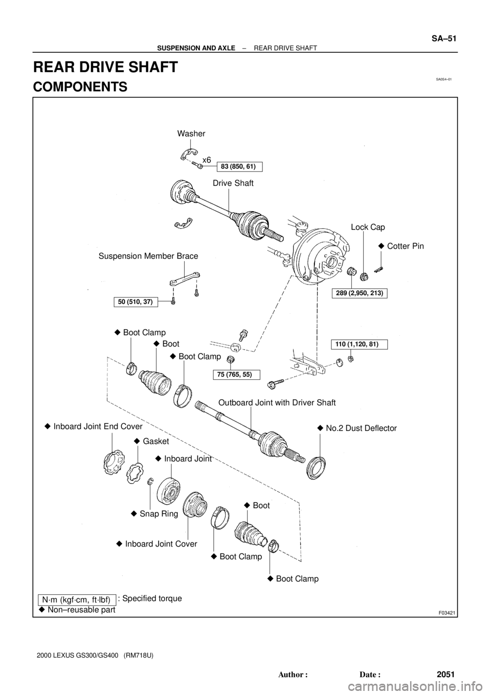
SA0S4±01
F03421
Suspension Member BraceDrive Shaft x6
Lock Cap
Outboard Joint with Driver Shaft� Cotter Pin
� Boot Clamp
� No.2 Dust Deflector � Inboard Joint End Cover
� GasketWasher
289 (2,950, 213)
110 (1,120, 81)
75 (765, 55)
� Boot Clamp � Boot
� Snap Ring
� Inboard Joint Cover
� Boot Clamp � Boot Clamp� Boot � Inboard Joint
N´m (kgf´cm, ft´lbf): Specified torque
� Non±reusable part
83 (850, 61)
50 (510, 37)
± SUSPENSION AND AXLEREAR DRIVE SHAFT
SA±51
2051 Author�: Date�:
2000 LEXUS GS300/GS400 (RM718U)
REAR DRIVE SHAFT
COMPONENTS
Page 1066 of 1111
F03450
± SUSPENSION AND AXLEREAR DRIVE SHAFT
SA±53
2053 Author�: Date�:
2000 LEXUS GS300/GS400 (RM718U)
(g) Using a brass bar and hammer, lightly tap the end of the
drive shaft, disengage the axle hub and remove the drive
shaft.
NOTICE:
Be careful not to damage the boots, end cover, speed sen-
sor rotor of the drive shaft and oil seal of the axle hub.
Page 1067 of 1111

DISASSEMBLY
1. CHECK DRIVE SHAFT
(a) Check that")
SA0S6±01
R05813
R00195
R11083Matchmarks
R00191
SST SA±54
± SUSPENSION AND AXLEREAR DRIVE SHAFT
2054 Author�: Date�:
2000 LEXUS GS300/GS400 (RM718U)
DISASSEMBLY
1. CHECK DRIVE SHAFT
(a) Check that operation of the joint is smooth within the slid-
ing region in the axial direction.
HINT:
If a large angle is used for the cross±groove type joint, the joint
will feel like it is catching, but this does not indicate an abnormal-
ity.
(b) Check that the boots are not cracked, damaged or leak-
ing.
(c) Check that there are no scratches on the speed sensor
rotor.
2. REMOVE END COVER
(a) Using a screwdriver, remove the end cover.
(b) Use bolts, nuts and washers to keep the inboard joint to-
gether.
NOTICE:
Tighten the bolt by hand to avoid scratching the flange sur-
face.
3. REMOVE BOOT CLAMPS
Using a side cutter or pliers, remove the 4 boot clamps.
4. REMOVE INBOARD JOINT
(a) Place matchmarks on the inboard joint and drive shaft.
NOTICE:
Do not puch the marks.
(b) Using a snap ring expander, remove the snap ring.
(c) Using SST, an extension bar and a press, press out the
inboard joint from the drive shaft.
SST 09726±12023 (09726±01031)
Page 1068 of 1111
R08193
R12345
± SUSPENSION AND AXLEREAR DRIVE SHAFT
SA±55
2055 Author�: Date�:
2000 LEXUS GS300/GS400 (RM718U)
(d) Mount the inboard joint in a soft jaw vise.
(e) Using a screwdriver and hammer, tap out the inboard joint
cover from the inboard joint.
NOTICE:
Make sure the cage and inner race are not positioned too
much to one side of the outer race.
5. REMOVE BOOTS
Remove the inboard and outboard joint boots.
6. REMOVE NO.2 DUST DEFLECTOR
(a) Mount the outboard joint in a soft jaw vise.
(b) Using a screwdriver, remove the No.2 dust deflector.
NOTICE:
Be careful not to damage the ABS speed sensor rotor.
Page 1069 of 1111

REASSEMBLY
1. INSTALL NEW")
SA0S7±01
R12766
SST
SA0721
Matchmarks
SA1328
Narrow
Wide
SA0830
R 11111
SA±56
± SUSPENSION AND AXLEREAR DRIVE SHAFT
2056 Author�: Date�:
2000 LEXUS GS300/GS400 (RM718U)
REASSEMBLY
1. INSTALL NEW NO.2 DUST DEFLECTOR
Using SST and a press, install a new No.2 dust deflector.
SST 09309±36010, 09502±12010
NOTICE:
Be careful not to damage the ABS speed sensor rotor.
2. ASSEMBLE INBOARD JOINT
If the joint has come apart, reassemble it in the following order.
(a) Align the matchmarks placed before removal.
HINT:
When the matchmarks have disappeared, do the following pro-
cedure.
(1) Install the inner race to the cage so that the in-
dented bevelled part of the inner race is on the op-
posite side to the bevelled top of the cage.
(2) Install the outer race so that the indented side of the
outer race is facing the same side as the bevelled
surface of the cage.
(3) Match the narrow projections of the inner race with
the wide projections of the outer race.
(b) Tilt the cage and inner race to the side and insert the balls
one by one.
NOTICE:
When the cage and inner race are tilted over, support the
joint with your hand to prevent the balls from falling out.
3. TEMPORARILY INSTALL NEW BOOTS AND NEW
BOOT CLAMPS
(a) Place 4 new boot clamps to each boots.
HINT:
Before installing the boots, wrap vinyl tape around the spline of
the shaft to prevent damaging the boots.
(b) Install the 2 boots to the drive shaft.
Page 1070 of 1111

Z12875
Cover
Inboard Joint
R00194
Matchmarks
W00623
SST30°
± SUSPENSION AND AXLEREAR DRIVE SHAFT
SA±57
2057 Author�: Date�:
2000 LEXUS G")
SA0679
FIPG
Seal Diameter
1.0 ± 1.8 mm
(0.039 ± 0.071 in.)
Z12875
Cover
Inboard Joint
R00194
Matchmarks
W00623
SST30°
± SUSPENSION AND AXLEREAR DRIVE SHAFT
SA±57
2057 Author�: Date�:
2000 LEXUS GS300/GS400 (RM718U)
4. INSTALL INBOARD JOINT COVER
(a) Apply FIPG to the inboard joint cover as shown in the il-
lustration.
FIPG:
Part No.08826±00801, THREE BOND 1121 or equiva-
lent
HINT:
Avoid applying an excessive amount to the surface.
(b) Remove grease from the surface of the inboard joint fac-
ing to the cover.
(c) Align the bolt holes of the cover with those of the inboard
joint, then insert the hexagon bolts.
(d) Use a plastic hammer to tap the rim of the inboard joint
cover into place. Do this in the order shown, and repeat
several times.
5. INSTALL INBOARD JOINT
(a) Align the matchmarks placed before removal.
(b) Using a brass bar and hammer, tap the inboard joint onto
the drive shaft.
NOTICE:
Check that the brass bar is touching the inner race, and not
the cage.
(c) Using a snap ring expander, install a new snap ring.
6. ASSEMBLE BOOTS TO JOINTS
Before assembling the boots, pack with only the same amount
of grease that was wiped off.
Grease capacity100 ± 105 g (3.5 ± 3.7 oz.)
HINT:
Use the grease supplied in the boot kit.
NOTICE:
�Keep grease off the joint connection groove of the
boot.
�Pack with grease all over the ball contact surface in-
side the joint.
7. INSTALL NEW BOOT CLAMPS TO BOTH BOOTS
(a) Position the clamp onto the boot.
(b) Place SST onto the clamp.
SST 09521±24010
(c) Tighten SST so that the clamp is pinched as shown in the
illustration.
NOTICE:
Do not overtighten the SST.
Page 1071 of 1111

(d) Using SST, adjust the clearance of the clamp.
SST 09240±0002")
R06938
SSTClearance
R08199
R07026
SA±58
± SUSPENSION AND AXLEREAR DRIVE SHAFT
2058 Author�: Date�:
2000 LEXUS GS300/GS400 (RM718U)
(d) Using SST, adjust the clearance of the clamp.
SST 09240±00020 (09242±00080)
Clearance: 0.8 mm (0.031 in.) or less
(e) The drive shaft is designed to move ±20 mm (0.79 in.)
from the normal position.
Drive shaft standard length:
RH598.5 mm (23.563 in.)
LH553.5 mm (21.791 in.)
8. INSTALL NEW END COVER
(a) Pack grease into the end cover.
Grease capacity50 ± 55 g (1.8 ±1.9 oz.)
(b) Remove grease from the surface of the inboard joint fac-
ing to the cover.
(c) Glue on a new gasket, with the glued side facing toward
the outer race side of the inboard joint.
(d) Align the bolt holes of the cover with those of the inboard
joint.
(e) Install the 6 hexagon bolts and washers from the end cov-
er side.
(f) Install the 6 nuts to the boot side.
(g) Using a 10 mm hexagon wrench, tighten the bolts. Do this
in the order shown, and repeat several times.
(h) Check that the claw of the end cover touches the inboard
joint.
9. CHECK DRIVE SHAFT (See page SA±54)