Page 674 of 1111

CHASSIS
INSPECTION
1. INSPECT STEERING LINKAGE
(a) Check the steering wheel freeplay.
(See page SR±8)
(b) Ch")
MA01S±01
± MAINTENANCECHASSIS
MA±7
50 Author�: Date�:
2000 LEXUS GS300/GS400 (RM718U)
CHASSIS
INSPECTION
1. INSPECT STEERING LINKAGE
(a) Check the steering wheel freeplay.
(See page SR±8)
(b) Check the steering linkage for looseness or damage.
Check that:
�Tie rod ends do not have excessive play.
�Dust seals and boots are not damaged.
�Boot clamps are not loose.
2. INSPECT SRS AIRBAG
(DRIVER'S SIDE: See page RS±15)
(PASSENGER'S SIDE: See page RS±29)
3. INSPECT STEERING GEAR HOUSING OIL
Check the steering gear housing for oil leakage.
4. INSPECT LOWER BALL JOINTS AND DUST COVERS
(a) Jack up the front of the vehicle and support it with stands.
(b) Make sure the front wheels are in a straight±ahead posi-
tion, and depress the brake pedal.
(c) Jack up the lower suspension arm until there is about half
a load on the front coil spring.
(d) Inspect the dust cover for damage.
5. CHECK AUTOMATIC TRANSMISSION AND
DIFFERENTIAL
Visually check the automatic transmission and differential for oil
leakage.
If leakage is found, check for the cause and repair it.
6. REPLACE AUTOMATIC TRANSMISSION FLUID
(See page DI±318)
7. REPLACE DIFFERENTIAL OIL
(See page SA±61)
Page 713 of 1111
PP±68
± PREPARATIONSUSPENSION AND AXLE
120 Author�: Date�:
2000 LEXUS GS300/GS400 (RM718U)
(09316±00071)Replacer ºFº
09325±40010Transmission Oil PlugRear differential
09330±00021Companion Flange Holding ToolRear differential
09502±12010Differential Bearing ReplacerRear drive shaft
Rear differential
09502±24010Bearing ReplacerRear differential
09520±00031Rear Axle Shaft PullerRear axle
09520±24010Differential Side Gear Shaft
PullerRear differential
09521±24010Drive Shaft Boot Clamping ToolRear drive shaft
09527±17011Rear Axle Shaft Bearing RemoverRear axle
09570±24010Differential Mounting Cushion
Remover & ReplacerDifferential mounting cushion
09608±04031Front Hub Inner Bearing Cone
ReplacerRear differential
09608±32010Steering Knuckle Oil Seal
ReplacerFront axle
Rear differential
09610±20012Pitman Arm PullerFront axle
Front suspension
Rear axle
Page 755 of 1111
F02411
Intermediate ShaftAdjusting Nut
Dust Boot
Center Support Bearing
� No.1 Dust
DeflectorPropeller Shaft
� Snap Ring
� No.2 Dust Deflector
N´m (kgf´cm, ft´lbf) : Specified torque
� Non±reusable part
* For use without SST
50 (515, 37)
* 69 (700, 51)
± PROPELLER SHAFTPROPELLER SHAFT ASSEMBLY
PR±3
1990 Author�: Date�:
2000 LEXUS GS300/GS400 (RM718U)
Page 759 of 1111

REPLACEMENT
1. SEPARATE INTERMEDIATE SHAFT")
PR030±01
Q06935
Matchmarks
Q06936
SST
Q06937
PR0253
± PROPELLER SHAFTPROPELLER SHAFT ASSEMBLY
PR±7
1994 Author�: Date�:
2000 LEXUS GS300/GS400 (RM718U)
REPLACEMENT
1. SEPARATE INTERMEDIATE SHAFT AND PROPEL-
LER SHAFT
(a) Place matchmarks on the intermediate shaft and propel-
ler shaft.
(b) Separate the intermediate shaft and propeller shaft.
(c) Remove the dust boot from the propeller shaft.
HINT:
If the dust boot is reused, remove it after wrapping vinyl tape
around the spline, so it will not be damaged.
2. REMOVE CENTER SUPPORT BEARING
(a) Using a snap ring expander, remove the snap ring.
(b) Using SST and a press, remove the center support bear-
ing and dust deflector.
SST 09950±00020
3. INSPECT INTERMEDIATE SHAFT AND PROPELLER
SHAFT RUNOUT
Using a dial indicator, check the runout of the shafts.
Maximum runout: 0.8 mm (0.031 in.)
If the runout exceeds the maximum, replace the propeller shaft
assembly.
4. INSPECT SPIDER BEARING
(a) Check if the spider bearing rotates smoothly.
(b) Check if there is any play in the spider bearing.
If necessary, replace the propeller shaft.
Page 760 of 1111

5. INSTALL CENTER SUPPORT BE")
Q06938
SST
Q06939
SST
Q06940
SST
Q06941Vinyl Tape
Q06935
Matchmarks PR±8
± PROPELLER SHAFTPROPELLER SHAFT ASSEMBLY
1995 Author�: Date�:
2000 LEXUS GS300/GS400 (RM718U)
5. INSTALL CENTER SUPPORT BEARING
NOTICE:
Be careful not to grip the propeller shaft tube too tightly in
a vise as this will cause deformation.
(a) Using SST and a press, install the center support bearing.
SST 09330±50010
(b) Using SST and a press, insert a new dust deflector until
it almost touches the rubber of the center support bearing.
SST 09608±00071, 09608±06041
(c) Using SST and a press, install a new dust deflector.
SST 09330±50010
(d) Using a snap ring expander, install a new snap ring.
6. ASSEMBLE INTERMEDIATE SHAFT AND PROPEL-
LER SHAFT
(a) Install the dust boot.
NOTICE:
Assemble after wrapping vinyl tape around the spline so it
will not damage the boot.
(b) Apply grease to the spline.
Grease:
Molybdenum disulphide lithium base, NLGI No.2
(c) Align the matchmarks and assemble the intermediate
shaft and propeller shaft.
(d) Cover the adjusting nut with the dust boot.
Page 924 of 1111
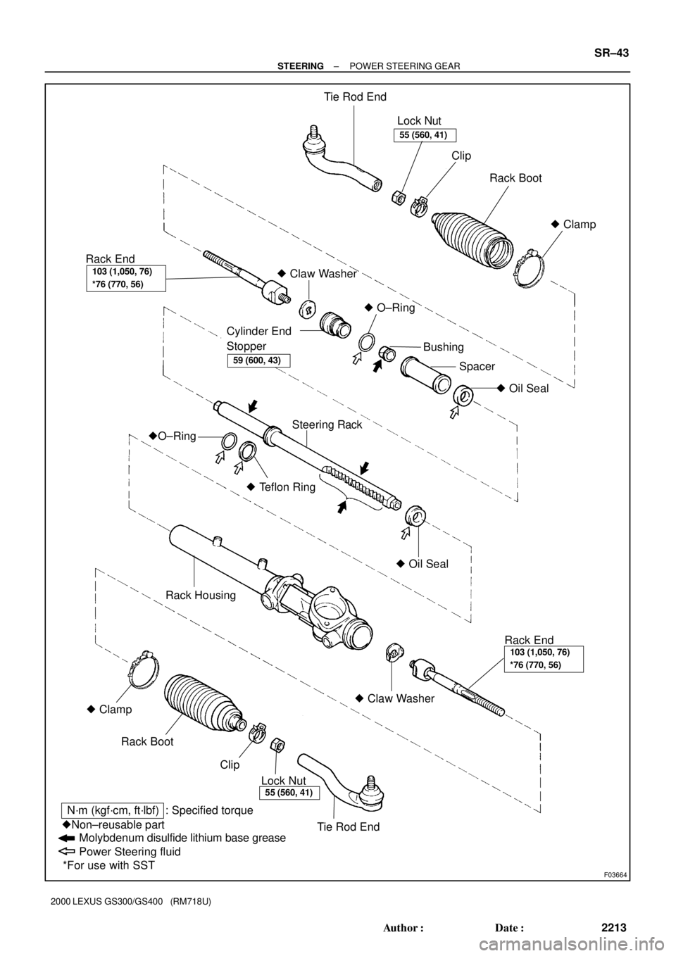
F03664
Tie Rod End
Lock Nut
Rack Boot
� Claw Washer
Steering Rack
� Claw Washer Rack HousingClip
� Clamp
� O±Ring
Bushing
� Oil Seal Spacer
Cylinder End
Stopper
�O±Ring
� Teflon Ring
� Oil Seal
Rack End
� Clamp
Rack Boot
Clip
Lock Nut
Tie Rod End
N´m (kgf´cm, ft´lbf) : Specified torque
�Non±reusable part
Molybdenum disulfide lithium base grease
Power Steering fluid
*For use with SST
55 (560, 41)
55 (560, 41)
103 (1,050, 76)
*76 (770, 56)
103 (1,050, 76)
*76 (770, 56)
59 (600, 43)
Rack End
± STEERINGPOWER STEERING GEAR
SR±43
2213 Author�: Date�:
2000 LEXUS GS300/GS400 (RM718U)
Page 927 of 1111
SR0E4±01
F02585
SST
F02587
SST
F02588
Matchmarks
F03698
F03699
SR±46
± STEERINGPOWER STEERING GEAR
2216 Author�: Date�:
2000 LEXUS GS300/GS400 (RM718U)
DISASSEMBLY
NOTICE:
When using a vise, do not overtighten it.
1. REMOVE 2 TURN PRESSURE TUBES
(a) Using SST, remove the tube.
SST 09633±00020
(b) Remove the union seat from the rack housing.
2. SECURE PS GEAR ASSEMBLY IN VISE
Using SST, secure the gear assembly in a vise, as shown in the
illustration.
SST 09612±00012
3. REMOVE RH AND LH TIE ROD ENDS AND LOCK
NUTS
Place matchmarks on the tie rod end and rack end.
4. REMOVE RH AND LH CLIPS, RACK BOOTS AND
CLAMPS
Using pliers, loosen the clamp, as shown in the illustration.
NOTICE:
�Be careful not to damage the boot.
�Mark the RH and LH boots.
5. REMOVE RH AND LH RACK ENDS AND CLAW WASH-
ERS
(a) Using a screwdriver and hammer, stake back the washer.
NOTICE:
Avoid any impact to the steering rack.
Page 937 of 1111

(c) Using a brass bar and hammer, stake the washer.")
R06400
Brass Bar
W00123
W04397
F02586
SSTFulcrum
Length
SR±56
± STEERINGPOWER STEERING GEAR
2226 Author�: Date�:
2000 LEXUS GS300/GS400 (RM718U)
(c) Using a brass bar and hammer, stake the washer.
NOTICE:
Avoid any impact to the rack.
14. INSTALL RH AND LH RACK BOOTS, CLAMPS AND
CLIPS
(a) Ensure that the tube hole is not clogged with grease.
HINT:
If the tube hole is clogged, the pressure inside the boot will
change after it is assembled and the steering wheel is turned.
(b) Install the boot.
NOTICE:
Be careful not to damage or twist the boot.
(c) Using pliers tighten a new clamp, as shown in the illustra-
tion.
15. INSTALL RH AND LH TIE ROD ENDS AND LOCK NUTS
(a) Screw the lock nut and tie rod end onto the rack end until
the matchmarks are aligned.
(b) After adjusting toe±in, torque the nut.
(See page SA±4)
Torque: 55 N´m (560 kgf´cm, 41 ft´lbf)
16. INSTALL 2 TURN PRESSURE TUBES
(a) Install a new union seat to the rack housing.
(b) Using SST, install the tube.
SST 09633±00020
Torque: 20 N´m (203 kgf´cm, 15 ft´lbf)
HINT:
�Use a torque wrench with a fulcrum length of 300 mm
(11.81 in.).
�This torque value is effective in case that SST is parallel
to a torque wrench.