Page 102 of 1111

D01090
Shift Lever Knob
Shift Lever Knob
Cover
Shift Lever
Sub±AssemblyShift Lever Detent Pin
Shift Lever Spring Damper
Compression Spring
Shift Lock Release Link
Indicator Lamp Wire Position Indicator Housing
Position Indicator
Lens
Slide Cover
Shift Lever Guide
Housing
Shift Lever
Anti±Rattle Cushion
Shift Lock
Plate Stopper
Shift Lever
Torsion Spring
Spring Holder
Lower Control Shaft Bushing
Lower Control Shaft Piece
Plate Washer
Shift Lever Boot Connecting Rod Swivel
Shift Lock Solenoid Link
Control ShaftPin
BulbConnector
Compression Spring
Plate WasherRoller
Spacer
Clip Control Lever
2.0 (20, 17 in.´lbf)
3.9 (40, 35 in.´lbf)
2.0 (20, 17 in.´lbf)
13 (128, 9)
Shift Lock
Control Unit
AssemblyShift Lock Release
Spring
No.1 Shift Lock
Switch PlateShift Lever Plate
Spacer
N´m (kgf´cm, ft´lbf)
: MP grease: Specified torqueShift Lever Cap
Wire Protector
� Shift Lever Nut
Shift Lock
Plate Stopper
Cap
� Slotted
Spring Pin
� Non±reusable part
± AUTOMATIC TRANSMISSIONFLOOR SHIFT ASSEMBLY
AT±15
1963 Author�: Date�:
2000 LEXUS GS300/GS400 (RM718U)
Page 107 of 1111
D01078
D01080
D01082
D01083
D01084
AT±20
± AUTOMATIC TRANSMISSIONFLOOR SHIFT ASSEMBLY
1968 Author�: Date�:
2000 LEXUS GS300/GS400 (RM718U)
14. REMOVE SHIFT LOCK CONTROL UNIT ASSEMBLY
(a) Remove the shift lock control unit assembly from the shift
lever plate.
(b) Push the shift lock solenoid link lightly, turn and remove
it.
(c) Remove the compression spring.
(d) Remove the slotted spring pin and separate the shift lock
solenoid link.
15. REMOVE SHIFT LEVER SUB±ASSEMBLY
(a) Using a pin punch and hammer, drive out the pin.
(b) Remove the shift lever sub±assembly.
(c) Remove the shift lever nut from the shift lever sub±as-
sembly.
16. REMOVE CONTROL LEVER, SPACER AND CON-
TROL SHAFT
(a) Remove the nut.
(b) Remove the 2 spacers and control shaft from the shift le-
ver plate.
(c) Disconnect the shift lever boot from shift lever plate.
(d) Remove the control lever.
Page 108 of 1111
D01085
± AUTOMATIC TRANSMISSIONFLOOR SHIFT ASSEMBLY
AT±21
1969 Author�: Date�:
2000 LEXUS GS300/GS400 (RM718U)
17. REMOVE CLIP, CONNECTING ROD SWIVEL, LOWER
CONTROL SHAFT BUSHING, LOWER CONTROL
SHAFT PIECE, PLATE WASHER AND SHIFT LEVER
BOOT FROM CONTROL LEVER
(a) Using pliers, remove the clip.
(b) Remove the connecting rod swivel, lower control shaft
bushing, lower control shaft piece, 2 plate washers and
shift lever boot from the control lever.
Page 110 of 1111

REASSEMBLY
HINT:
Before reassembly, apply MP greas")
AT065±01
D01085
D01084
Lip
D01083
D01082
AT±22
± AUTOMATIC TRANSMISSIONFLOOR SHIFT ASSEMBLY
1970 Author�: Date�:
2000 LEXUS GS300/GS400 (RM718U)
REASSEMBLY
HINT:
Before reassembly, apply MP grease to the parts indicated by
arrows.
(See page AT±13)
1. INSTALL CLIP, CONNECTING ROD SWIVEL, LOWER
CONTROL SHAFT BUSHING, LOWER CONTROL
SHAFT PIECE, PLATE WASHER AND SHIFT LEVER
BOOT TO CONTROL LEVER
(a) Install the shift lever boot, 2 plate washers, lower control
shaft piece, lower control shaft bushing and connecting
rod swivel to the control lever.
(b) Using pliers, install the clip.
2. INSTALL CONTROL LEVER, SPACER AND CONTROL
SHAFT
(a) Connect the shift lever boot to the shift lever plate.
HINT:
Pull out the 3 lips of the shift lever boot securely, as shown in
the illustration.
(b) Install the control shaft and 2 spacers.
(c) Install and torque the nut.
Torque: 13 N´m (128 kgf´cm, 9 ft´lbf)
3. INSTALL SHIFT LEVER SUB±ASSEMBLY
(a) Install a new shift lever nut to the shift lever sub±assem-
bly.
HINT:
Insert the shift lever nut securely until it fits and check there is
no looseness.
Page 395 of 1111
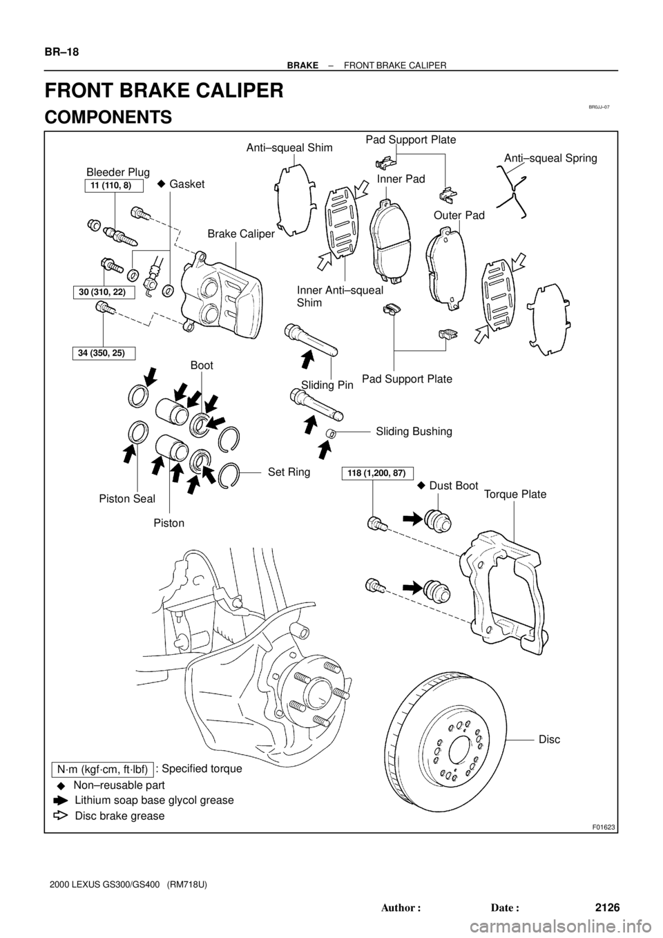
BR0JJ±07
F01623
11 (110, 8)
34 (350, 25)
Bleeder Plug
� Gasket
Brake Caliper
Anti±squeal ShimPad Support Plate
Inner Pad
Inner Anti±squeal
ShimOuter PadAnti±squeal Spring
Boot
Piston Seal
PistonSet RingSliding Bushing Pad Support Plate
Sliding Pin
� Dust Boot
Torque Plate
Disc
N´m (kgf´cm, ft´lbf): Specified torque
Lithium soap base glycol grease
Disc brake grease Non±reusable part
�
30 (310, 22)
118 (1,200, 87)
BR±18
± BRAKEFRONT BRAKE CALIPER
2126 Author�: Date�:
2000 LEXUS GS300/GS400 (RM718U)
FRONT BRAKE CALIPER
COMPONENTS
Page 405 of 1111
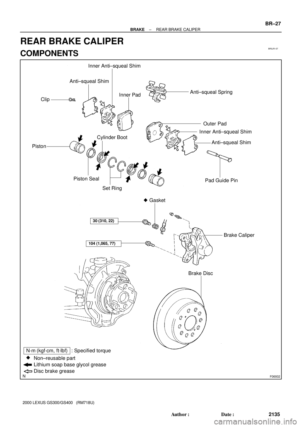
BR0JR±07
F06932
� Gasket Piston
Piston Seal
Brake DiscPad Guide Pin Cylinder Boot Inner Anti±squeal Shim
Non±reusable part
Lithium soap base glycol grease
Disc brake grease
: Specified torque
�
30 (310, 22)
Set RingAnti±squeal Shim Anti±squeal Spring Anti±squeal Shim
Brake Caliper
Inner Anti±squeal ShimOuter Pad Inner Pad
104 (1,065, 77)
Clip
N´m (kgf´cm, ft´lbf)
± BRAKEREAR BRAKE CALIPER
BR±27
2135 Author�: Date�:
2000 LEXUS GS300/GS400 (RM718U)
REAR BRAKE CALIPER
COMPONENTS
Page 407 of 1111
BR0JT±03
F01640
Z09008
150 mm
(5.91 in.)50 mm
(1.97 in.)
12 mm
(0.472 in.)
F01641
F01642
± BRAKEREAR BRAKE CALIPER
BR±29
2137 Author�: Date�:
2000 LEXUS GS300/GS400 (RM718U)
DISASSEMBLY
1. REMOVE SET RINGS AND BOOTS
Using a screwdriver, remove the 2 set rings and 2 boots.
2. REMOVE PISTONS FROM CYLINDER
(a) Prepare a wooden plate to hold the pistons.
(b) Place the plate between the pistons and insert a pad on
one side.
(c) Use compressed air to remove the pistons alternately
from the caliper.
CAUTION:
Do not place your fingers in front of the piston when using
compressed air.
3. REMOVE PISTON SEALS
Using a screwdriver, remove the 2 piston seals from the caliper.
Page 432 of 1111
F06045
Reservoir Set Screw
Hydraulic Brake Booster
Oil Pressure
Sensor
No. 1 Accumulator
BracketNo. 2
Accumulator
Bracket
No. 1 Pump
Bracket
Actuator No. 1 TubeAccumulator
�O±ring
Spring
Silencer Tube Grommet
No. 2 Piston
No. 1 PistonSnap Ring
BootClevis Reservoir
Cap
No. 2 Pump
Bracket Sleeve
Collar
Booster Pump Motor
Cushion Washer Actuator Hose
15 (155, 11)
54 (550, 36)
1.7 (17.5, 15.2 in.´lbf)
81 (830, 60)
Non±reusable part
�
Cushion Cushion
Collar
Cushion
25 (260, 19)
N´m (kgf´cm, ft´lbf) : Specified torqueSpacer
�O±ring
Clamp
�Wire Harness
± BRAKEHYDRAULIC BRAKE BOOSTER
BR±49
2157 Author�: Date�:
2000 LEXUS GS300/GS400 (RM718U)