Page 453 of 1111
CH049±01
P10639
Pulley
P10637
B02022
29 mm
Socket
Wrench
B01648
Wire
Clip
P10835
Turn
SST (B)SST (A)
± CHARGING (2JZ±GE)GENERATOR
CH±13
1615 Author�: Date�:
2000 LEXUS GS300/GS400 (RM718U)
REASSEMBLY
1. PLACE DRIVE END FRAME ON PULLEY
2. INSTALL ROTOR TO DRIVE END FRAME
3. INSTALL RECTIFIER END FRAME
(a) Place the generator washer on the rotor.
(b) Using a 29 mm socket wrench and press, slowly press in
the rectifier end frame.
(c) Install the 3 nuts.
Torque: 4.5 N´m (46 kgf´cm, 40 in.´lbf)
(d) Install the wire clip with the nut.
Torque: 5.4 N´m (55 kgf´cm, 48 in.´lbf)
4. INSTALL PULLEY
(a) Install the pulley to the rotor shaft by tightening the pulley
nut by hand.
(b) Hold SST (A) with a torque wrench, and tighten SST (B)
clockwise to the specified torque.
SST 09820±63010
Torque: 39 N´m (400 kgf´cm, 29 ft´lbf)
(c) Check that SST (A) is secured to the pulley shaft.
Page 454 of 1111
Z00045
Turn
SST (C)
P10836
Turn
SST (B)SST (A)
B01649
Inside
Rubber
Insulator
B01650
Push
B01651
Seal Plate CH±14
± CHARGING (2JZ±GE)GENERATOR
1616 Author�: Date�:
2000 LEXUS GS300/GS400 (RM718U)
(d) Mount SST (C) in a vise.
(e) Insert SST (B) into SST (C), and attach the pulley nut to
SST (C).
(f) To torque the pulley nut, turn SST (A) in the direction
shown in the illustration.
Torque: 110.5 N´m (1,125 kgf´cm, 81 ft´lbf)
(g) Remove the generator from SST (C).
(h) Turn SST (B), and remove SST (A and B).
5. INSTALL RECTIFIER HOLDER
(a) Install the 4 rubber insulators on the lead wires.
(b) Install the rectifier holder while pushing it with the 4
screws.
Torque: 2.9 N´m (30 kgf´cm, 26 in.´lbf)
6. INSTALL VOLTAGE REGULATOR AND BRUSH
HOLDER
(a) Place the seal plate on the rectifier end frame.
Page 455 of 1111
B01652
Upward
Long
Long
B01653
B01654
Plate Terminal
± CHARGING (2JZ±GE)GENERATOR
CH±15
1617 Author�: Date�:
2000 LEXUS GS300/GS400 (RM718U)
(b) Place the voltage regulator and brush holder on the recti-
fier end frame.
NOTICE:
Be careful of the holder installation direction.
(c) Install the 5 screws.
Torque: 2.0 N´m (20 kgf´cm, 18 in.´lbf)
(d) Place the brush holder cover on the brush holder.
7. INSTALL REAR END COVER
(a) Install the end cover and plate terminal with the bolt and
3 nuts.
Torque:
Nut 4.4 N´m (45 kgf´cm, 39 in.´lbf)
Bolt 3.9 N´m (39 kgf´cm, 35 in.´lbf)
(b) Install the terminal insulator with the nut.
Torque: 6.5 N´m (67 kgf´cm, 58 in.´lbf)
8. CHECK THAT ROTOR ROTATES SMOOTHLY
Page 459 of 1111
CH045±01
B02027
Turn
B01646
B01962
Engine
Wire Clamp
Pipe Clamp
B01963
Pipe Bracket
CH±6
± CHARGING (2JZ±GE)GENERATOR
1608 Author�: Date�:
2000 LEXUS GS300/GS400 (RM718U)
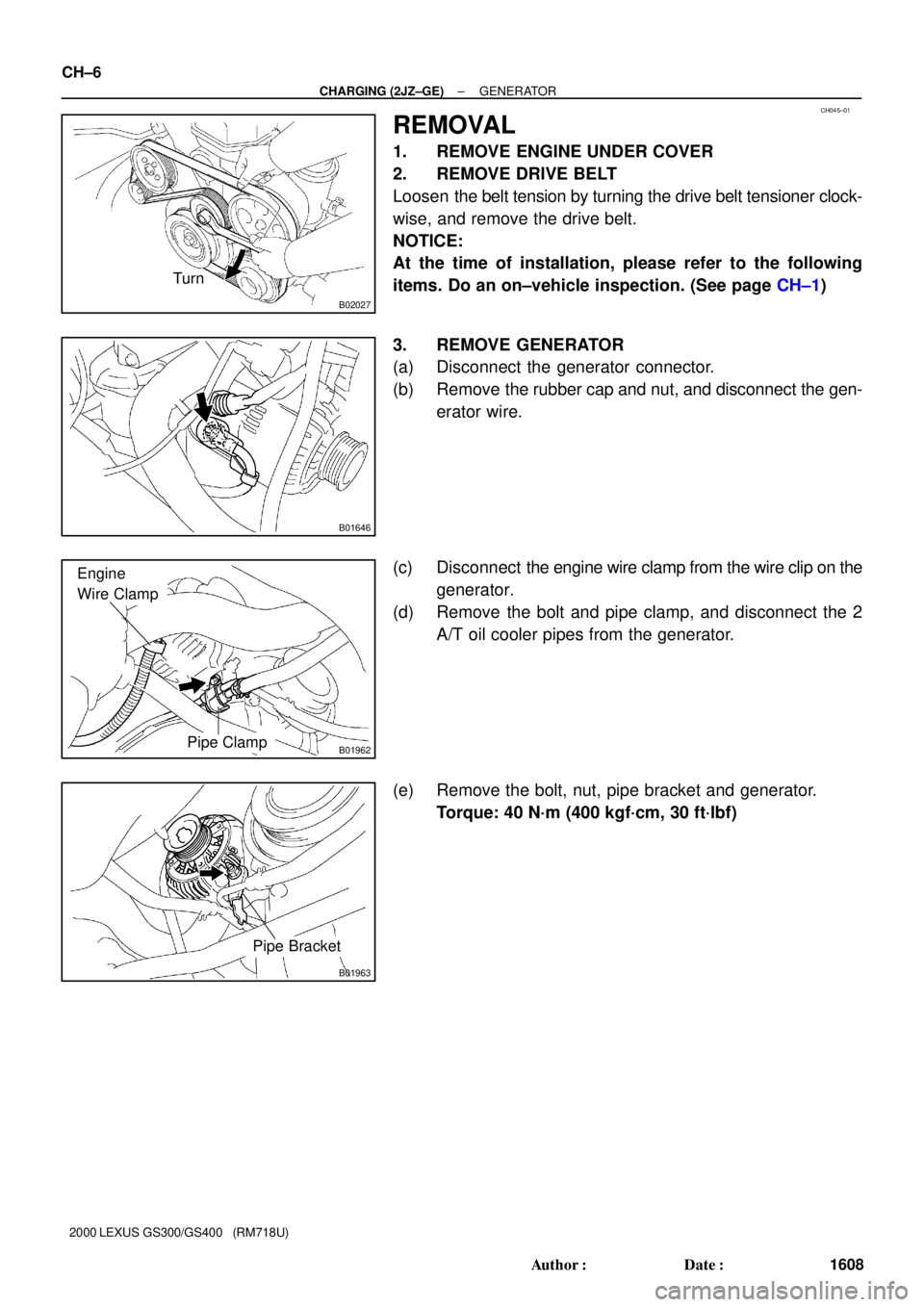
REMOVAL
1. REMOVE ENGINE UNDER COVER
2. REMOVE DRIVE BELT
Loosen the belt tension by turning the drive belt tensioner clock-
wise, and remove the drive belt.
NOTICE:
At the time of installation, please refer to the following
items. Do an on±vehicle inspection. (See page CH±1)
3. REMOVE GENERATOR
(a) Disconnect the generator connector.
(b) Remove the rubber cap and nut, and disconnect the gen-
erator wire.
(c) Disconnect the engine wire clamp from the wire clip on the
generator.
(d) Remove the bolt and pipe clamp, and disconnect the 2
A/T oil cooler pipes from the generator.
(e) Remove the bolt, nut, pipe bracket and generator.
Torque: 40 N´m (400 kgf´cm, 30 ft´lbf)
Page 460 of 1111
B01655
CH046±05
B01654
Plate Terminal
B01997
B01650
P10835
Turn
SST (B)SST (A)
± CHARGING (2JZ±GE)GENERATOR
CH±7
1609 Author�: Date�:
2000 LEXUS GS300/GS400 (RM718U)
DISASSEMBLY
1. REMOVE REAR END COVER
(a) Remove the nut and terminal insulator.
(b) Remove the bolt, 3 nuts, plate terminal and end cover.
2. REMOVE BRUSH HOLDER AND VOLTAGE REGULA-
TOR
(a) Remove the brush holder cover from the brush holder.
(b) Remove the 5 screws, brush holder and voltage regulator.
(c) Remove the seal plate from the rectifier end frame.
3. REMOVE RECTIFIER HOLDER
(a) Remove the 4 screws and rectifier holder.
(b) Remove the 4 rubber insulators.
4. REMOVE PULLEY
(a) Hold SST (A) with a torque wrench, and tighten SST (B)
clockwise to the specified torque.
SST 09820±63010
Torque: 39 N´m (400 kgf´cm, 29 ft´lbf)
(b) Check that SST (A) is secured to the rotor shaft.
Page 468 of 1111
CO0A5±01
P 1111 7
ProtrusionJiggle Valve
± COOLING (2JZ±GE)THERMOSTAT
CO±13
1551 Author�: Date�:
2000 LEXUS GS300/GS400 (RM718U)
INSTALLATION
1. PLACE THERMOSTAT IN WATER INLET
(a) Install a new gasket to the thermostat.
(b) Align the jiggle valve of the thermostat with the protrusion
of the water inlet.
2. INSTALL WATER INLET
Install the water inlet with the 2 nuts.
Torque: 9.0 N´m (90 kgf´cm, 80 in.´lbf)
3. FILL WITH ENGINE COOLANT
4. START ENGINE AND CHECK FOR COOLANT LEAKS
Page 475 of 1111
COOLANT
1540 Author�: Date�:
2000 LEXUS GS300/GS400 (RM718U)
REPLACEMENT
1. DRAIN ENGINE COOLAN")
CO09X±03
Z07402
Drain Plug
Drain Plug
B01611
Drain Plug
Rubber
HoseConnect
CO±2
± COOLING (2JZ±GE)COOLANT
1540 Author�: Date�:
2000 LEXUS GS300/GS400 (RM718U)
REPLACEMENT
1. DRAIN ENGINE COOLANT
(a) Remove the radiator cap.
CAUTION:
To avoid the danger of being burned, do not remove the ra-
diator cap while the engine and radiator are still hot, as fluid
and steam can be blown out under pressure.
(b) Loosen the 2 drain plugs (for the engine and radiator),
and drain the coolant.
HINT:
To prevent the coolant from spraying over the cylinder block,
connect the rubber hose (inside diameter 6 ± 8 mm) in the mar-
ket to the union pipe under the drain plug.
(c) Close the drain plugs.
Torque: 30 N´m (300 kgf´cm, 22 ft´lbf) for engine
2. FILL ENGINE COOLANT
(a) Slowly fill the system with coolant.
�Use of improper coolants may damage engine cool-
ing system.
�Use ºToyota Long Life Coolantº or equivalent and
mix it with plain water according to the manufac-
ture's directions.
�Use of the coolant which includes more than 50%
[freezing protection down to ±35°C (±31°F)] or 60%
[freezing protection down to ±50°C (±58°F)] of eth-
ylene ±glycol is recommended, but not more than
70%.
NOTICE:
�Do not use an alcohol type coolant or plain water
alone.
�The coolant should be mixed with plain water (prefer-
able demineralized water or distilled water).
Capacity (w/ Heater):
7.7 liters (8.1 US qts, 6.8 lmp. qts)
(b) Install the radiator cap.
(c) Start the engine, and bleed the cooling system.
(d) Refill the reservoir with coolant until it reaches the ºFULLº
line.
3. CHECK ENGINE COOLANT FOR LEAKS
4. CHECK ENGINE COOLANT SPECIFIC GRAVITY COR-
RECTLY
Page 476 of 1111

CO0AB±03
B01862
75°
Pipe
CO0317O±Ring� Normal X TwistedX Twisted
B01868
CORRECT
WRONG
Ta pTank
Plate
Lock
CO1206
Dimension B
Punch Assembly
Overhaul HandleStopper BoltPartSST
CO±20
± COOLING (2JZ±GE)RADIATOR
1558 Author�: Date�:
2000 LEXUS GS300/GS400 (RM718U)
REASSEMBLY
1. INSTALL OIL COOLER TO LOWER TANK
(a) Install 2 new O±rings to the oil cooler.
(b) Install the oil cooler to the lower tank with the 2 plate
washers and 2 nuts.
Torque: 8.3 N´m (85 kgf´cm, 74 in.´lbf)
(c) Install the cooler pipes in the direction indicated in the il-
lustration.
Torque: 14.7 N´m (150 kgf´cm, 11 ft´lbf)
2. INSPECT LOCK PLATE FOR DAMAGE
HINT:
�If the sides of the lock plate groove are deformed, reas-
sembly of the tank will be impossible.
�Therefore, first correct any deformation with pliers or simi-
lar object. Water leakage will result if the bottom of the
lock plate groove is damaged or dented.
NOTICE:
The radiator can only be recaulked 2 times. After the 2nd
time, the radiator core must be replaced.
3. INSTALL NEW O±RINGS AND TANKS
(a) After checking that there are no foreign objects in the lock
plate groove, install a new O±ring without twisting it.
HINT:
When cleaning the lock plate groove, lightly rub it with sand pa-
per without scratching it.
(b) Install the tank without damaging the O±ring.
(c) Tap the lock plate with a soft±faced hammer so that there
is no gap between it and the tank.
4. ASSEMBLE SST
SST 09230±01010, 09231±14010
(a) Install the punch assembly to the overhaul handle, insert-
ing it in the hole in part A as shown in the illustration.
(b) While gripping the handle, adjust the stopper bolt so that
dimension B is as shown in the illustration.
Dimension B: 8.4 mm (0.331 in.)