Page 406 of 1111
BR0JS±06
F01639
BR±28
± BRAKEREAR BRAKE CALIPER
2136 Author�: Date�:
2000 LEXUS GS300/GS400 (RM718U)
REMOVAL
1. REMOVE REAR WHEEL
Torque: 103 N´m (1,050 kgf´cm, 76 ft´lbf)
2. DISCONNECT FLEXIBLE HOSE
Remove the union bolt and gasket from the caliper, then discon-
nect the flexible hose from the caliper. Use a container to catch
brake fluid as it drains out.
Torque: 30 N´m (310 kgf´cm, 22 ft´lbf)
HINT:
At the time of installation, please refer to the following item.
Install the flexible hose lock securely in the lock hole in the cali-
per.
3. REMOVE CALIPER
(a) Remove the 2 installation bolts.
Torque: 104 N´m (1,065 kgf´cm, 77 ft´lbf)
(b) Remove the caliper.
4. REMOVE BRAKE PADS (See page BR±25)
(a) Remove the anti±squeal spring.
(b) Remove the clip and pad guide pin.
(c) Remove the 2 pads with the 4 anti±squeal shims.
Page 408 of 1111

INSPECTION
1. MEASURE PAD LINING THICKNESS
Using a ruler, measure the pad lining")
BR0JU±07
F01643
F01644
F01645
BR±30
± BRAKEREAR BRAKE CALIPER
2138 Author�: Date�:
2000 LEXUS GS300/GS400 (RM718U)
INSPECTION
1. MEASURE PAD LINING THICKNESS
Using a ruler, measure the pad lining thickness.
Standard thickness: 10.5 mm (0.413 in.)
Minimum thickness: 1.0 mm (0.039 in.)
Replace the pads if the thickness is less than the minimum or
if it shows signs of uneven wear.
2. MEASURE DISC THICKNESS
Using a micrometer, measure the disc thickness.
Standard thickness: 12.0 mm (0.472 in.)
Minimum thickness: 10.5 mm (0.413 in.)
Replace the disc if the thickness of the disc is at the minimum
thickness or less. Replace the disc or grind it on a lathe if it is
badly scored or worn unevenly.
3. MEASURE DISC RUNOUT
Using a dial indicator, measure the disc runout at a position 10
mm (0.394 in.) away from the out side edge.
Maximum disc runout: 0.05 mm (0.0020 in.)
If the disc's runout is maximum value or greater, check the bear-
ing play in the axial direction and check the axle hub runout
(See page SA±44). If the bearing play and axle hub runout are
not abnormal, adjust the disc runout or grind it on a ºOn±Carº
brake lathe.
4. IF NECESSARY, ADJUST DISC RUNOUT
(a) Remove the 3 hub nuts and disc. Turn the disc 1/5 and
reinstall the disc. Install and torque the 3 hub nuts.
Torque: 103 N´m (1,050 kgf´cm, 76 ft´lbf)
(b) Remeasure the disc runout. Make a note of the runout
and the disc's position on the hub.
(c) Repeat (b) until the disc has been installed on the 3 re-
maining hub positions.
(d) If the minimum runout recorded in (b) and (c) is less than
0.05 mm (0.0020 in.), install the disc in that position.
(e) If the minimum runout recorded in (b) and (c) is greater
than 0.05 mm (0.0020 in.), replace the disc and repeat
step 3.
Page 411 of 1111
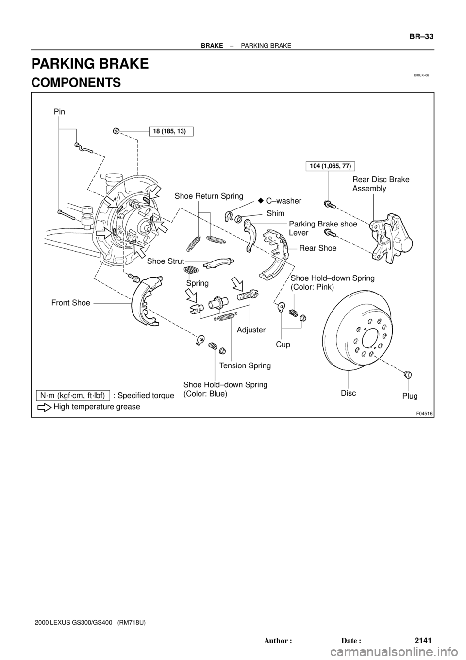
BR0JX±06
F04516
Pin
18 (185, 13)
Shoe Return Spring
104 (1,065, 77)
Rear Disc Brake
Assembly
Front Shoe
� C±washer
Shim
Parking Brake shoe
Lever
Rear Shoe
Shoe Strut
SpringShoe Hold±down Spring
(Color: Pink)
Adjuster
Cup
Tension Spring
Shoe Hold±down Spring
(Color: Blue)
DiscPlug
High temperature grease
N´m (kgf´cm, ft´lbf) : Specified torque
± BRAKEPARKING BRAKE
BR±33
2141 Author�: Date�:
2000 LEXUS GS300/GS400 (RM718U)
PARKING BRAKE
COMPONENTS
Page 412 of 1111

DISASSEMBLY
1. REMOVE REAR WHEEL
Torque: 103 N´m (1,050 kgf´cm, 76 ft")
BR0JY±03
F01647
F01648
F01649
F01650
F01651
BR±34
± BRAKEPARKING BRAKE
2142 Author�: Date�:
2000 LEXUS GS300/GS400 (RM718U)
DISASSEMBLY
1. REMOVE REAR WHEEL
Torque: 103 N´m (1,050 kgf´cm, 76 ft´lbf)
2. REMOVE REAR DISC BRAKE ASSEMBLY
(a) Remove the 2 mounting bolts and remove the disc brake
assembly.
Torque: 104 N´m (1,065 kgf´cm, 77 ft´lbf)
(b) Suspend the disc brake securely and so the hose is not
stretched.
3. REMOVE DISC
(a) Release the parking brake pedal.
(b) Place matchmarks on the disc and rear axle hub.
(c) Remove the disc.
HINT:
�If the disc cannot be removed easily, turn the shoe adjust-
er until the wheel turns freely.
�If there are no matchmarks, temporarily install the disc,
then measure the disc runout and install the disc in posi-
tion (See page BR±30).
4. REMOVE SHOE RETURN SPRINGS
Using needle±nose pliers, remove the 2 shoe return springs.
5. REMOVE SHOE STRUT WITH SPRING
HINT:
At the time of reassembly, install the strut with the spring facing
forward.
6. REMOVE FRONT SHOE AND ADJUSTER
(a) Slide out the front shoe and remove the shoe adjuster.
(b) Disconnect the tension spring and remove the front shoe.
(c) Remove the 2 cups, shoe hold±down spring and pin.
7. REMOVE REAR SHOE AND TENSION SPRING
(a) Slide out the rear shoe.
(b) Remove the tension spring from the rear shoe.
(c) Disconnect the parking brake cable from the parking
brake shoe lever.
(d) Remove the 2 cups, shoe hold±down spring and pin.
Page 430 of 1111

(l) Observe the procedure in step (k) and bleed left rear
brake line.
(m) Disconnect the actuator checker (SST)")
F02851
BR±8
± BRAKEBRAKE FLUID
2116 Author�: Date�:
2000 LEXUS GS300/GS400 (RM718U)
(l) Observe the procedure in step (k) and bleed left rear
brake line.
(m) Disconnect the actuator checker (SST) and sub±wire har-
ness (SST) from the actuator.
SST 09990±00150, 09990±00480
(n) Connect the 2 connectors to the hydraulic brake booster.
(o) Clear the DTC (See page DI±389).
4. BLEED BRAKE LINE
(a) Connect the vinyl tube to the brake caliper.
(b) Depress the brake pedal several times, then loosen the
bleeder plug with the pedal held down.
(c) At the point when fluid stops coming out, tighten the
bleeder plug, then release the brake pedal.
(d) Repeat (b) and (c) until all the air in the fluid has been bled
out.
(e) Repeat the above procedure to bleed the brake line for
each wheel.
Torque: 11 N´m (110 kgf´cm, 8 ft´lbf)
5. CHECK FLUID LEVEL IN RESERVOIR
(a) With the ignition switch OFF, depress the brake pedal
more than 40 times.
HINT:
When a pressure in power supply system is released, reaction
force becomes heavy and stroke becomes shorter.
(b) Remove the reservoir cap. Add brake fluid up to the
ºMAXº line.
Fluid: SAE J1703 or FMVSS NO. 116 DOT3
Page 431 of 1111
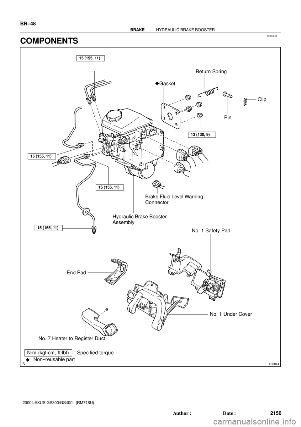
BR0K8±09
F06044Non±reusable part
��Gasket
Hydraulic Brake Booster
Assembly
13 (130, 9)
End PadBrake Fluid Level Warning
ConnectorReturn Spring
No. 7 Heater to Register DuctNo. 1 Under Cover No. 1 Safety Pad
15 (155, 11)
15 (155, 11)
15 (155, 11)
15 (155, 11)
N´m (kgf´cm, ft´lbf) : Specified torquePin
Clip BR±48
± BRAKEHYDRAULIC BRAKE BOOSTER
2156 Author�: Date�:
2000 LEXUS GS300/GS400 (RM718U)
COMPONENTS
Page 432 of 1111
F06045
Reservoir Set Screw
Hydraulic Brake Booster
Oil Pressure
Sensor
No. 1 Accumulator
BracketNo. 2
Accumulator
Bracket
No. 1 Pump
Bracket
Actuator No. 1 TubeAccumulator
�O±ring
Spring
Silencer Tube Grommet
No. 2 Piston
No. 1 PistonSnap Ring
BootClevis Reservoir
Cap
No. 2 Pump
Bracket Sleeve
Collar
Booster Pump Motor
Cushion Washer Actuator Hose
15 (155, 11)
54 (550, 36)
1.7 (17.5, 15.2 in.´lbf)
81 (830, 60)
Non±reusable part
�
Cushion Cushion
Collar
Cushion
25 (260, 19)
N´m (kgf´cm, ft´lbf) : Specified torqueSpacer
�O±ring
Clamp
�Wire Harness
± BRAKEHYDRAULIC BRAKE BOOSTER
BR±49
2157 Author�: Date�:
2000 LEXUS GS300/GS400 (RM718U)
Page 433 of 1111

REMOVAL
NOTICE:
�Before starting the work, make sure that the ignit")
BR0K9±04
F06046
SST
F01655
SST
F06047
BR±50
± BRAKEHYDRAULIC BRAKE BOOSTER
2158 Author�: Date�:
2000 LEXUS GS300/GS400 (RM718U)
REMOVAL
NOTICE:
�Before starting the work, make sure that the ignition
switch is OFF and depress the brake pedal more than
40 times.
�As high pressure is applied to the brake actuator tube
No. 1, never deform it.
�Until the work is over, do not turn the ignition switch
ON.
1. DRAW OUT FLUID WITH SYRINGE
NOTICE:
Do not let brake fluid remain on a painted surface. Wash it
off immediately.
2. REMOVE NO. 1 UNDER COVER (See page BO±88)
3. REMOVE END PAD AND NO. 1 SAFETY PAD
4. REMOVE NO. 7 HEATER TO REGISTER DUCT
5. DISCONNECT BRAKE LINES
Using SST, disconnect the 4 brake lines.
SST 09023±00100
Torque: 15 N´m (155 kgf´cm, 11 ft´lbf)
6. DISCONNECT LEFT FRONT WHEEL BRAKE LINE
Using SST, disconnect the left front wheel brake line from the
flexible hose.
SST 09023±00100
Torque: 15 N´m (155 kgf´cm, 11 ft´lbf)
7. REMOVE 2 BRAKE LINE CLAMPS
8. DISCONNECT LEVEL WARNING SWITCH CONNEC-
TOR
9. DISCONNECT 4 CONNECTORS
10. REMOVE PEDAL RETURN SPRING, CLIP AND CLE-
VIS PIN
11. REMOVE HYDRAULIC BRAKE BOOSTER ASSEMBLY
(a) Loosen the lock nut, then remove the clevis and lock nut.
Torque: 25 N´m (260 kgf´cm, 19 ft´lbf)
(b) Remove the 4 booster installation nuts.
Torque: 13 N´m (130 kgf´cm, 9 ft´lbf)
(c) Remove the booster assembly and gasket.