(3) Grasp the wheel cover and pull straight out-
ward. This will remove the wheel cover from the
wheel.
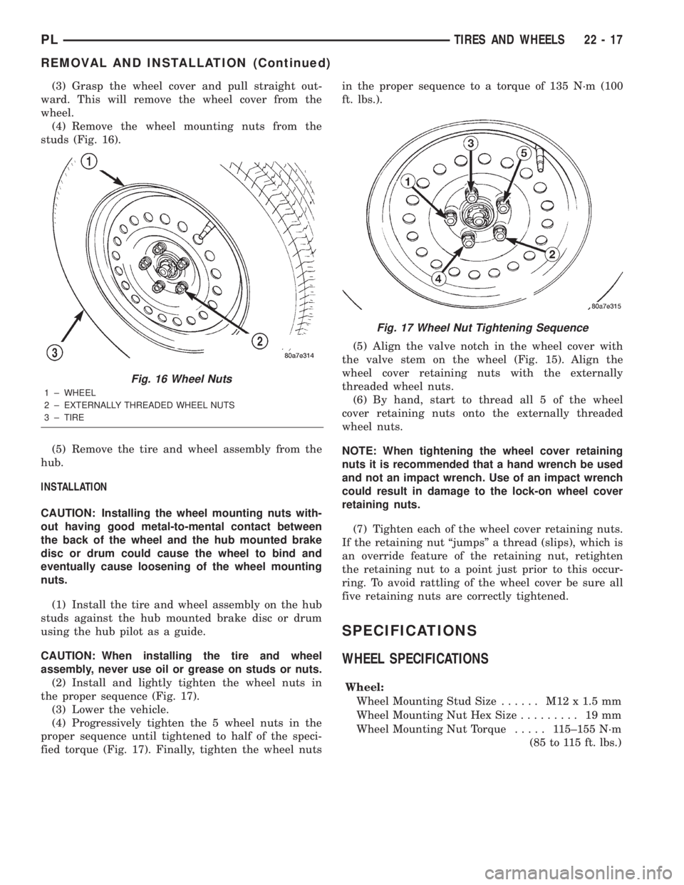
(4) Remove the wheel mounting nuts from the
studs (Fig. 16).
(5) Remove the tire and wheel assembly from the
hub.
INSTALLATION
CAUTION: Installing the wheel mounting nuts with-
out having good metal-to-mental contact between
the back of the wheel and the hub mounted brake
disc or drum could cause the wheel to bind and
eventually cause loosening of the wheel mounting
nuts.
(1) Install the tire and wheel assembly on the hub
studs against the hub mounted brake disc or drum
using the hub pilot as a guide.
CAUTION: When installing the tire and wheel
assembly, never use oil or grease on studs or nuts.
(2) Install and lightly tighten the wheel nuts in
the proper sequence (Fig. 17).
(3) Lower the vehicle.
(4) Progressively tighten the 5 wheel nuts in the
proper sequence until tightened to half of the speci-
fied torque (Fig. 17). Finally, tighten the wheel nutsin the proper sequence to a torque of 135 N´m (100
ft. lbs.).
(5) Align the valve notch in the wheel cover with
the valve stem on the wheel (Fig. 15). Align the
wheel cover retaining nuts with the externally
threaded wheel nuts.
(6) By hand, start to thread all 5 of the wheel
cover retaining nuts onto the externally threaded
wheel nuts.
NOTE: When tightening the wheel cover retaining
nuts it is recommended that a hand wrench be used
and not an impact wrench. Use of an impact wrench
could result in damage to the lock-on wheel cover
retaining nuts.
(7) Tighten each of the wheel cover retaining nuts.
If the retaining nut ªjumpsº a thread (slips), which is
an override feature of the retaining nut, retighten
the retaining nut to a point just prior to this occur-
ring. To avoid rattling of the wheel cover be sure all
five retaining nuts are correctly tightened.
SPECIFICATIONS
WHEEL SPECIFICATIONS
Wheel:
Wheel Mounting Stud Size...... M12x1.5mm
Wheel Mounting Nut Hex Size......... 19mm
Wheel Mounting Nut Torque..... 115±155 N´m
(85 to 115 ft. lbs.)
Fig. 16 Wheel Nuts
1 ± WHEEL
2 ± EXTERNALLY THREADED WHEEL NUTS
3 ± TIRE
Fig. 17 Wheel Nut Tightening Sequence
PLTIRES AND WHEELS 22 - 17
REMOVAL AND INSTALLATION (Continued)