2000 DODGE NEON instrument cluster
[x] Cancel search: instrument clusterPage 254 of 1285

INSTRUMENT CLUSTER LAMPS
WARNINGS/INDICATORS
The instrument cluster warning/indicator lamps
are all serviceable Light Emitting Diodes (LED's).
The instrument cluster must first be removed, refer
to Instrument Cluster Removal and Installation in
this section, and then the defective LED just turns
out with needle nose pliers.
ILLUMINATION LAMPS
The high beam indicator, turn signals, and illumi-
nation bulbs are also serviceable. The instrument
cluster must first be removed, refer to Instrument
Cluster Removal and Installation in this section, and
then the defective bulb and socket turns out. The
bulb locations are printed on the back cover of the
instrument cluster.
INSTRUMENT PANEL ASSEMBLY
REMOVAL
(1) Disconnect and isolate the battery negative
cable (Fig. 6).
(2) Push seats back to their full back position.
(3) Using a trim stick (special tool #C-4755), gently
pry out on left and right A-pillar trim moldings and
remove.
(4) Remove top cover. Refer to Top Cover Removal
and Installation in this section.
(5) Gently pull up on cluster bezel and remove
from vehicle.
(6) Gently pull rearward on left lower instrument
panel cover and remove from vehicle.
CAUTION: Lock the steering wheel in the straight
ahead position. This will prevent clockspring dam-
age when the steering wheel rotates freely.
(7) Remove steering column. Refer to Group 19
Steering, Steering Column Removal and Installation.
(8) Remove left and right instrument panel end-
caps.
(9) Remove left and right cowl side panels.
(10) Remove center console. Refer to Group 23
Body, Center Console Removal and Installation.
(11) Depress the sides of the Data Link Connector
(DLC) and remove from instrument panel reinforce-
ment.
(12) Remove four bulkhead instrument panel
retaining screws.
(13) Remove two bolts on top of the brake pedal
support bracket.
(14) Remove two center support mounting bolts.
(15) Remove left and right A-pillar mounting bolts,
two on each side.(16) Disconnect right side antenna connector.
(17) Remove left and right A-pillar door harness
connectors (Fig. 10).
(18) Disconnect two harness connectors to hvac at
right top instrument panel (Fig. 11).
Fig. 10 A-Pillar Door Harness Connector
1 ± INSTRUMENT PANEL HARNESS CONNECTOR
2 ± DOOR CHECK STRAP
3 ± DOOR HARNESS CONNECTOR
Fig. 11 Instrument Panel to HVAC Harness Connectors
1 ± HVAC HARNESS CONNECTORS
PLINSTRUMENT PANEL SYSTEMS 8E - 7
REMOVAL AND INSTALLATION (Continued)
Page 256 of 1285
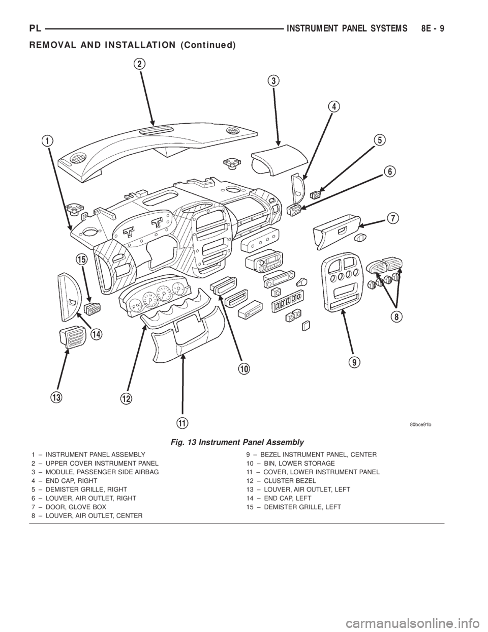
Fig. 13 Instrument Panel Assembly
1 ± INSTRUMENT PANEL ASSEMBLY
2 ± UPPER COVER INSTRUMENT PANEL
3 ± MODULE, PASSENGER SIDE AIRBAG
4 ± END CAP, RIGHT
5 ± DEMISTER GRILLE, RIGHT
6 ± LOUVER, AIR OUTLET, RIGHT
7 ± DOOR, GLOVE BOX
8 ± LOUVER, AIR OUTLET, CENTER9 ± BEZEL INSTRUMENT PANEL, CENTER
10 ± BIN, LOWER STORAGE
11 ± COVER, LOWER INSTRUMENT PANEL
12 ± CLUSTER BEZEL
13 ± LOUVER, AIR OUTLET, LEFT
14 ± END CAP, LEFT
15 ± DEMISTER GRILLE, LEFT
PLINSTRUMENT PANEL SYSTEMS 8E - 9
REMOVAL AND INSTALLATION (Continued)
Page 257 of 1285
INSTRUMENT PANEL CENTER BEZEL
REMOVAL
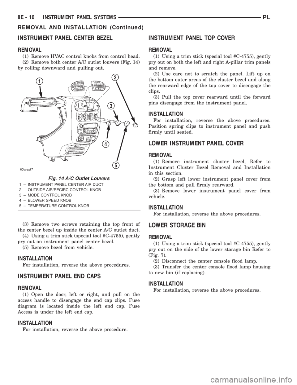
(1) Remove HVAC control knobs from control head.
(2) Remove both center A/C outlet louvers (Fig. 14)
by rolling downward and pulling out.
(3) Remove two screws retaining the top front of
the center bezel up inside the center A/C outlet duct.
(4) Using a trim stick (special tool #C-4755), gently
pry out on instrument panel center bezel.
(5) Remove bezel from vehicle.
INSTALLATION
For installation, reverse the above procedures.
INSTRUMENT PANEL END CAPS
REMOVAL
(1) Open the door, left or right, and pull on the
access handle to disengage the end cap clips. Fuse
diagram is located inside the left end cap. Fuse
Access is under the left end cap.
INSTALLATION
For installation, reverse the above procedure.
INSTRUMENT PANEL TOP COVER
REMOVAL
(1) Using a trim stick (special tool #C-4755), gently
pry out on both the left and right A-pillar trim panels
and remove.
(2) Use care not to scratch the panel. Lift up on
the bottom outer areas of the cluster bezel and along
the rearward edge of the top cover to disengage the
clips.
(3) Pull the top cover rearward until the forward
pins disengage from the instrument panel.
INSTALLATION
For installation, reverse the above procedures.
Position spring clips to instrument panel and push
firmly until seated.
LOWER INSTRUMENT PANEL COVER
REMOVAL
(1) Remove instrument cluster bezel, Refer to
Instrument Cluster Bezel Removal and Installation
in this section.
(2) Grasp left lower instrument panel cover from
the bottom and pull firmly rearward.
(3) Remove lower instrument panel cover from
vehicle.
INSTALLATION
For installation, reverse the above procedures.
LOWER STORAGE BIN
REMOVAL
(1) Using a trim stick (special tool #C-4755), gently
pry out on the side of the lower storage bin Refer to
(Fig. 7).
(2) Disconnect the center console flood lamp.
(3) Transfer the center console flood lamp housing
to new bin (if replacing).
INSTALLATION
For installation, reverse the above procedures.
Fig. 14 A/C Outlet Louvers
1 ± INSTRUMENT PANEL CENTER AIR DUCT
2 ± OUTSIDE AIR/RECIRC CONTROL KNOB
3 ± MODE CONTROL KNOB
4 ± BLOWER SPEED KNOB
5 ± TEMPERATURE CONTROL KNOB
8E - 10 INSTRUMENT PANEL SYSTEMSPL
REMOVAL AND INSTALLATION (Continued)
Page 258 of 1285
STEERING COLUMN SHROUDS
REMOVAL
(1) Remove lower instrument panel cover. Refer to
Lower Instrument Panel Cover Removal and Instal-
lation in this section.
(2) Remove instrument cluster bezel. Refer to
Instrument Cluster Bezel Removal and Installation
in this section.
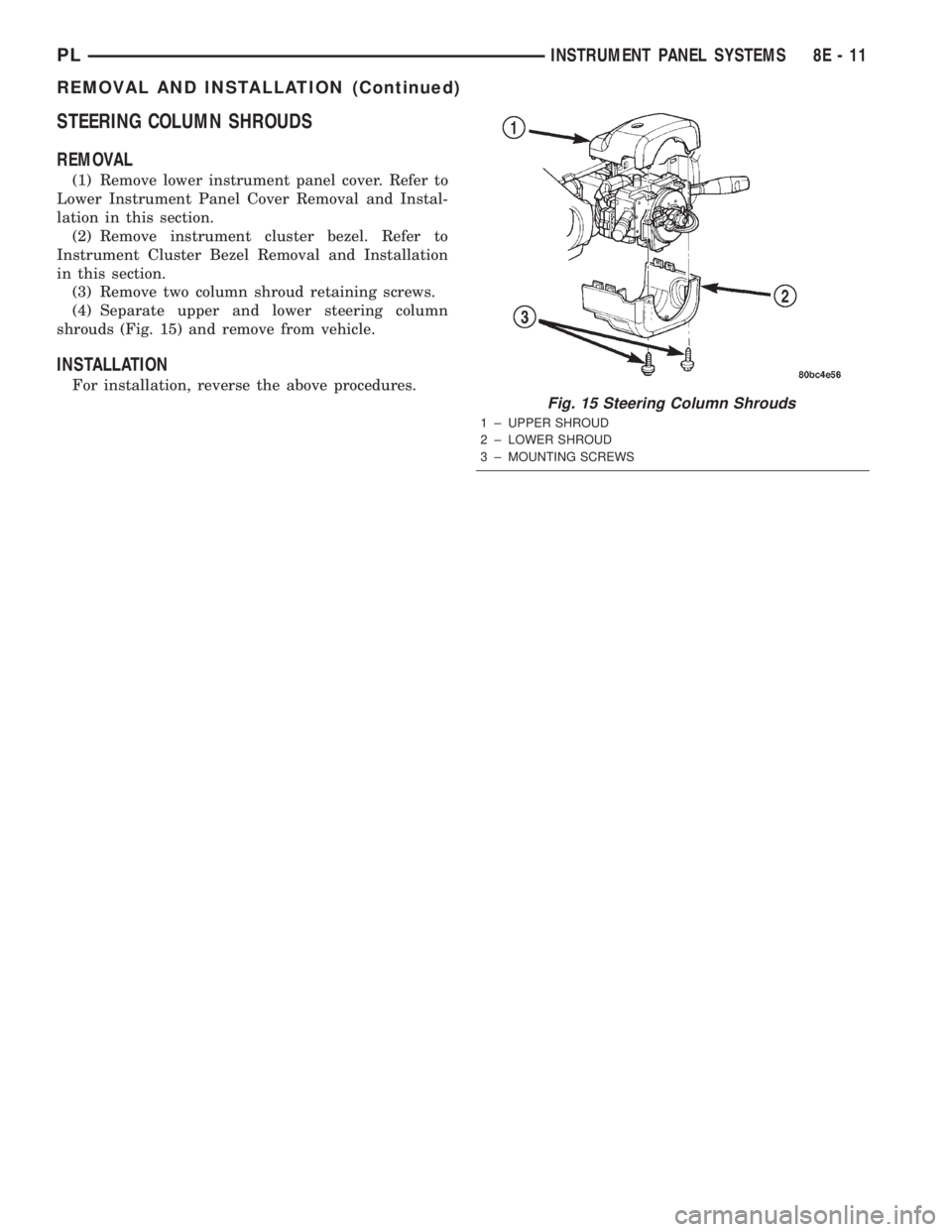
(3) Remove two column shroud retaining screws.
(4) Separate upper and lower steering column
shrouds (Fig. 15) and remove from vehicle.
INSTALLATION
For installation, reverse the above procedures.
Fig. 15 Steering Column Shrouds
1 ± UPPER SHROUD
2 ± LOWER SHROUD
3 ± MOUNTING SCREWS
PLINSTRUMENT PANEL SYSTEMS 8E - 11
REMOVAL AND INSTALLATION (Continued)
Page 263 of 1285
(1) Disconnect the negative battery cable.
(2) Remove the floor console. Refer to Group 23,
Body for the procedure.
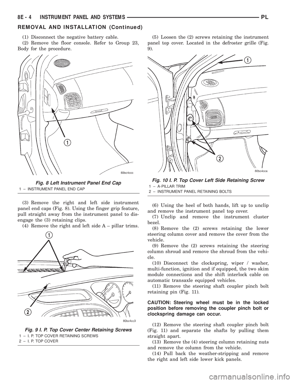
(3) Remove the right and left side instrument
panel end caps (Fig. 8). Using the finger grip feature,
pull straight away from the instrument panel to dis-
engage the (3) retaining clips.
(4) Remove the right and left side A ± pillar trims.(5) Loosen the (2) screws retaining the instrument
panel top cover. Located in the defroster grille (Fig.
9).
(6) Using the heel of both hands, lift up to unclip
and remove the instrument panel top cover.
(7) Unclip and remove the instrument cluster
bezel.
(8) Remove the (2) screws retaining the lower
steering column cover and remove the cover from the
vehicle.
(9) Remove the (2) screws retaining the steering
column shroud and remove the shroud from the vehi-
cle.
(10) Disconnect the clockspring, wiper / washer,
multi-function, ignition and if equipped, the two skim
module connections and the shift interlock cable on
automatic transaxle equipped vehicles.
(11) Remove the steering shaft coupler pinch bolt
retaining pin (Fig. 11).
CAUTION: Steering wheel must be in the locked
position before removing the coupler pinch bolt or
clockspring damage can occur.
(12) Remove the steering shaft coupler pinch bolt
(Fig. 11) and separate the shafts by pulling them
straight apart.
(13) Remove the (4) steering column retaining nuts
and remove the column from the vehicle.
(14) Pull back the weather-stripping and remove
the right and left side lower kick panels.
Fig. 8 Left Instrument Panel End Cap
1 ± INSTRUMENT PANEL END CAP
Fig. 9 I. P. Top Cover Center Retaining Screws
1 ± I. P. TOP COVER RETAINING SCREWS
2 ± I. P. TOP COVER
Fig. 10 I. P. Top Cover Left Side Retaining Screw
1 ± A-PILLAR TRIM
2 ± INSTRUMENT PANEL RETAINING BOLTS
8E - 4 INSTRUMENT PANEL AND SYSTEMSPL
REMOVAL AND INSTALLATION (Continued)
Page 267 of 1285
(17) Install the A/C outlet registers in the center
instrument bezel.
(18) Install the right and left side lower kick pan-
els. Reposition the weather-strip in its original posi-
tion.
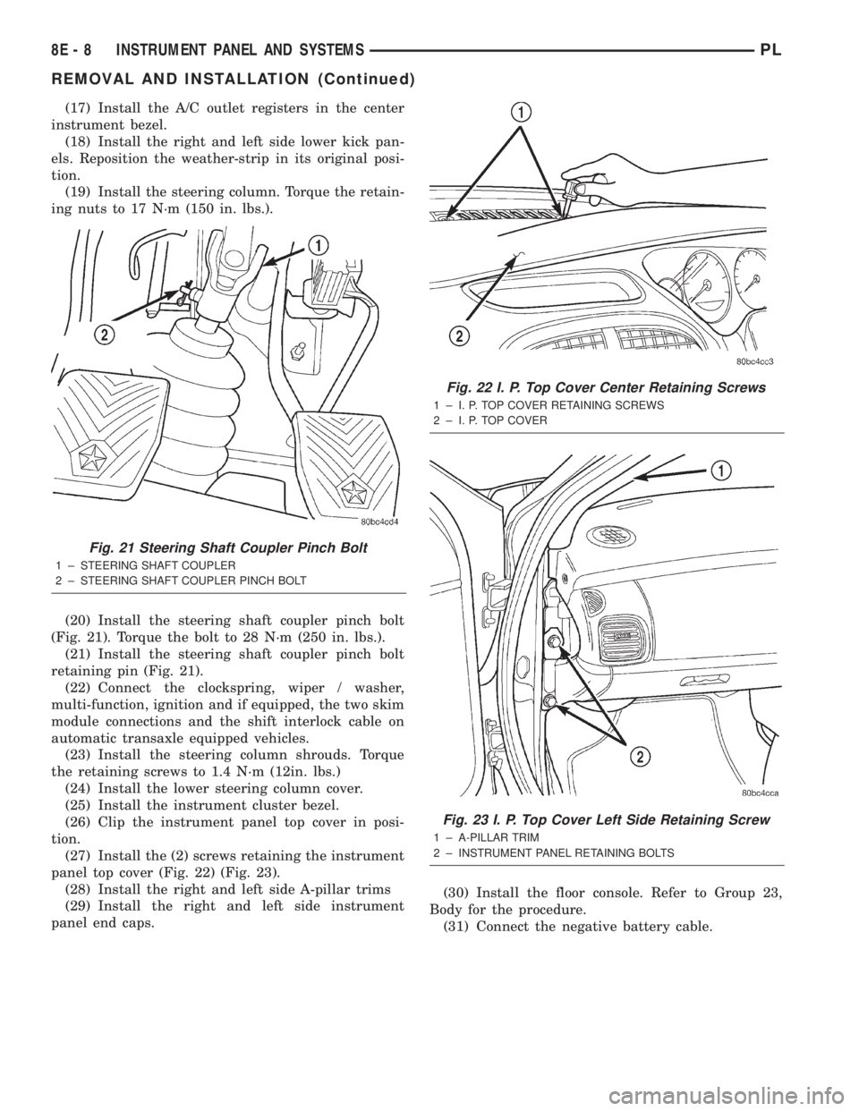
(19) Install the steering column. Torque the retain-
ing nuts to 17 N´m (150 in. lbs.).
(20) Install the steering shaft coupler pinch bolt
(Fig. 21). Torque the bolt to 28 N´m (250 in. lbs.).
(21) Install the steering shaft coupler pinch bolt
retaining pin (Fig. 21).
(22) Connect the clockspring, wiper / washer,
multi-function, ignition and if equipped, the two skim
module connections and the shift interlock cable on
automatic transaxle equipped vehicles.
(23) Install the steering column shrouds. Torque
the retaining screws to 1.4 N´m (12in. lbs.)
(24) Install the lower steering column cover.
(25) Install the instrument cluster bezel.
(26) Clip the instrument panel top cover in posi-
tion.
(27) Install the (2) screws retaining the instrument
panel top cover (Fig. 22) (Fig. 23).
(28) Install the right and left side A-pillar trims
(29) Install the right and left side instrument
panel end caps.(30) Install the floor console. Refer to Group 23,
Body for the procedure.
(31) Connect the negative battery cable.
Fig. 21 Steering Shaft Coupler Pinch Bolt
1 ± STEERING SHAFT COUPLER
2 ± STEERING SHAFT COUPLER PINCH BOLT
Fig. 22 I. P. Top Cover Center Retaining Screws
1 ± I. P. TOP COVER RETAINING SCREWS
2 ± I. P. TOP COVER
Fig. 23 I. P. Top Cover Left Side Retaining Screw
1 ± A-PILLAR TRIM
2 ± INSTRUMENT PANEL RETAINING BOLTS
8E - 8 INSTRUMENT PANEL AND SYSTEMSPL
REMOVAL AND INSTALLATION (Continued)
Page 293 of 1285
The integrated switch assembly is mounted to the
left hand side of the steering column. When the
driver wishes to signal his intentions to change direc-
tion of travel, he moves the lever upward to cause
the right signals to flash and downward to cause the
left signals to flash. After completion of a turn the
system is deactivated automatically. As the steering
wheel returns to the straight ahead position, a can-
celing cam molded to the clockspring mechanism
comes in contact with the cancel actuator on the turn
signal multi-function switch assembly. The cam lobe,
pushing on the cancel actuator, returns the switch to
the off position.
If only momentary signaling such as indication of a
lane change is desired, the switch is actuated to a
left or right intermediate detent position. In this
position the signal lamps flash as described above,
but the switch returns to the OFF position as soon as
the lever is released.
When the system is activated, one of two indicator
lamps mounted in the instrument cluster flashes in
unison with the turn signal lamps, indicating to the
driver that the system is operating.
DESCRIPTION AND OPERATION
HAZARD WARNING SYSTEM
The hazard warning system is actuated by a push
button located in the muti-function switch (Fig. 1) on
the top of the steering column between the steering
wheel and the instrument panel. The hazard switch
is identified with a double triangle on front of the
button.
HEADLAMP SWITCH
The headlamp switch is part of the Multi-Function
Switch (Fig. 1). Refer to Multi-Function Switch Diag-
nosis and Testing, Turn Signal and Hazard Warning
Flasher Diagnosis table in this section.
COMBINATION FLASHER
The turn signal flasher and the hazard warning
flasher are combined into one unit called a combina-
tion flasher (combo-flasher). The combo- flasher con-
trols the flashing of the hazard warning system and
the turn signal system. An inoperative bulb or incom-
plete turn signal circuit will cause the flasher rate to
double.
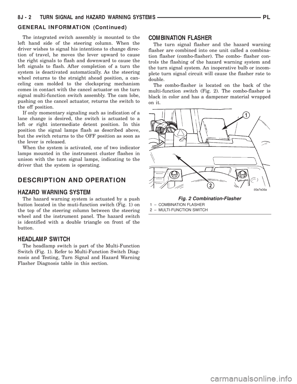
The combo-flasher is located on the back of the
multi-function switch (Fig. 2). The combo-flasher is
black in color and has a dampener material wrapped
on it.
Fig. 2 Combination-Flasher
1 ± COMBINATION FLASHER
2 ± MULTI-FUNCTION SWITCH
8J - 2 TURN SIGNAL and HAZARD WARNING SYSTEMSPL
GENERAL INFORMATION (Continued)
Page 294 of 1285
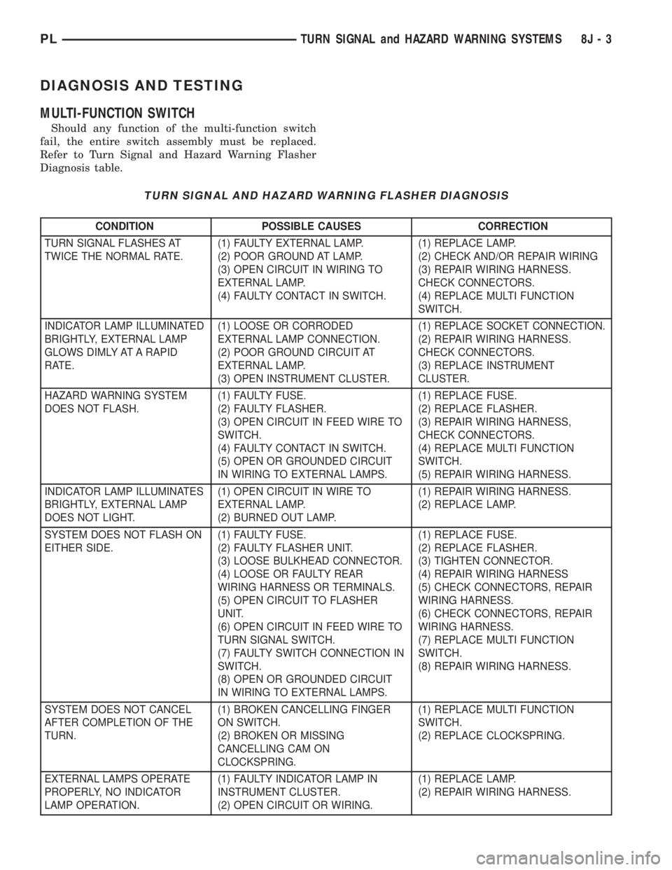
DIAGNOSIS AND TESTING
MULTI-FUNCTION SWITCH
Should any function of the multi-function switch
fail, the entire switch assembly must be replaced.
Refer to Turn Signal and Hazard Warning Flasher
Diagnosis table.
TURN SIGNAL AND HAZARD WARNING FLASHER DIAGNOSIS
CONDITION POSSIBLE CAUSES CORRECTION
TURN SIGNAL FLASHES AT
TWICE THE NORMAL RATE.(1) FAULTY EXTERNAL LAMP.
(2) POOR GROUND AT LAMP.
(3) OPEN CIRCUIT IN WIRING TO
EXTERNAL LAMP.
(4) FAULTY CONTACT IN SWITCH.(1) REPLACE LAMP.
(2) CHECK AND/OR REPAIR WIRING
(3) REPAIR WIRING HARNESS.
CHECK CONNECTORS.
(4) REPLACE MULTI FUNCTION
SWITCH.
INDICATOR LAMP ILLUMINATED
BRIGHTLY, EXTERNAL LAMP
GLOWS DIMLY AT A RAPID
RATE.(1) LOOSE OR CORRODED
EXTERNAL LAMP CONNECTION.
(2) POOR GROUND CIRCUIT AT
EXTERNAL LAMP.
(3) OPEN INSTRUMENT CLUSTER.(1) REPLACE SOCKET CONNECTION.
(2) REPAIR WIRING HARNESS.
CHECK CONNECTORS.
(3) REPLACE INSTRUMENT
CLUSTER.
HAZARD WARNING SYSTEM
DOES NOT FLASH.(1) FAULTY FUSE.
(2) FAULTY FLASHER.
(3) OPEN CIRCUIT IN FEED WIRE TO
SWITCH.
(4) FAULTY CONTACT IN SWITCH.
(5) OPEN OR GROUNDED CIRCUIT
IN WIRING TO EXTERNAL LAMPS.(1) REPLACE FUSE.
(2) REPLACE FLASHER.
(3) REPAIR WIRING HARNESS,
CHECK CONNECTORS.
(4) REPLACE MULTI FUNCTION
SWITCH.
(5) REPAIR WIRING HARNESS.
INDICATOR LAMP ILLUMINATES
BRIGHTLY, EXTERNAL LAMP
DOES NOT LIGHT.(1) OPEN CIRCUIT IN WIRE TO
EXTERNAL LAMP.
(2) BURNED OUT LAMP.(1) REPAIR WIRING HARNESS.
(2) REPLACE LAMP.
SYSTEM DOES NOT FLASH ON
EITHER SIDE.(1) FAULTY FUSE.
(2) FAULTY FLASHER UNIT.
(3) LOOSE BULKHEAD CONNECTOR.
(4) LOOSE OR FAULTY REAR
WIRING HARNESS OR TERMINALS.
(5) OPEN CIRCUIT TO FLASHER
UNIT.
(6) OPEN CIRCUIT IN FEED WIRE TO
TURN SIGNAL SWITCH.
(7) FAULTY SWITCH CONNECTION IN
SWITCH.
(8) OPEN OR GROUNDED CIRCUIT
IN WIRING TO EXTERNAL LAMPS.(1) REPLACE FUSE.
(2) REPLACE FLASHER.
(3) TIGHTEN CONNECTOR.
(4) REPAIR WIRING HARNESS
(5) CHECK CONNECTORS, REPAIR
WIRING HARNESS.
(6) CHECK CONNECTORS, REPAIR
WIRING HARNESS.
(7) REPLACE MULTI FUNCTION
SWITCH.
(8) REPAIR WIRING HARNESS.
SYSTEM DOES NOT CANCEL
AFTER COMPLETION OF THE
TURN.(1) BROKEN CANCELLING FINGER
ON SWITCH.
(2) BROKEN OR MISSING
CANCELLING CAM ON
CLOCKSPRING.(1) REPLACE MULTI FUNCTION
SWITCH.
(2) REPLACE CLOCKSPRING.
EXTERNAL LAMPS OPERATE
PROPERLY, NO INDICATOR
LAMP OPERATION.(1) FAULTY INDICATOR LAMP IN
INSTRUMENT CLUSTER.
(2) OPEN CIRCUIT OR WIRING.(1) REPLACE LAMP.
(2) REPAIR WIRING HARNESS.
PLTURN SIGNAL and HAZARD WARNING SYSTEMS 8J - 3