2000 DODGE NEON instrument cluster
[x] Cancel search: instrument clusterPage 87 of 1285
RED BRAKE WARNING LAMP
The red BRAKE warning lamp is located in the
instrument panel cluster and illuminates when a low
brake fluid condition occurs or when the parking
brake lever is applied with the ignition key in the
ON position. In addition, the red BRAKE warning
lamp illuminates when the ignition switch is moved
from the OFF to the ON or CRANK position. This is
done to check the bulb's operation.
Problems with this system will generally be of the
type where the warning lamp fails to turn on when it
should, or remains on when it should not.
The red BRAKE warning lamp LED is supplied
with current anytime the ignition switch is ON. The
bulb is illuminated by completing the ground circuit
using any of the following components:
²the brake fluid level switch located in the mas-
ter cylinder reservoir
²the parking brake switch mounted on the park-
ing brake lever (Fig. 10)
²the ignition switch when the ignition switch is
first moved to the ON or CRANK position
²the mechanical instrument cluster (MIC) (with
ABS)
²the ABS electronic brake distribution (EBD)
The brake fluid level switch is located in the brake
fluid reservoir of the master cylinder assembly (Fig.
1). The purpose of the switch is to provide the driver
with an early warning that the brake fluid level inthe master cylinder reservoir has dropped below an
acceptable level.
As the fluid drops below the minimum level, the
fluid level switch closes and grounds the red BRAKE
warning lamp circuit. This turns on the red BRAKE
warning lamp. At this time, the master cylinder fluid
reservoir must be checked and filled to the full mark
with DOT 3 brake fluid. An abnormal loss of brake
fluid in the master cylinder fluid reservoir could be
caused by a leak in the hydraulic system. The entire
brake hydraulic system should be checked for evi-
dence of a leak.
The red BRAKE warning lamp can be turned on by
the MIC in the case where the ABS is experiencing a
problem where the amber ABS warning lamp needs
to be illuminated and cannot. The MIC will then illu-
minate the red BRAKE warning lamp.
BRAKE LAMP SWITCH
The brake lamp switch is located under the instru-
ment panel, at the brake pedal arm (Fig. 13). It con-
trols operation of the vehicle's stop lamps. Also, if the
vehicle is equipped with speed control, the brake
lamp switch will deactivate the speed control when
the brake pedal is depressed.
When the brake pedal is depressed, the brake lamp
switch contacts are closed, completing the circuit to
the stop lamps, thus illuminating the stop lamps and
the center-high-mounted stop lamp (CHMSL).
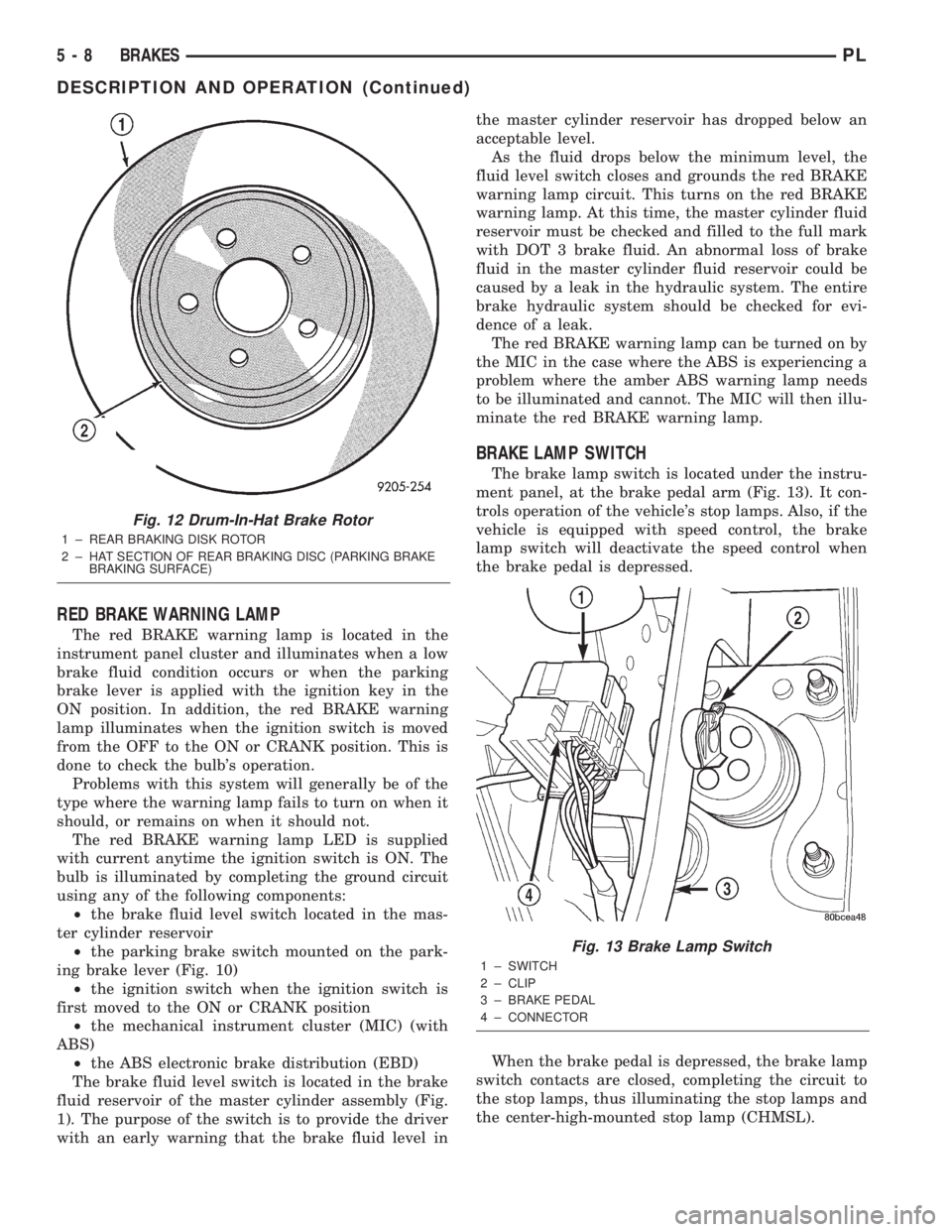
Fig. 12 Drum-In-Hat Brake Rotor
1 ± REAR BRAKING DISK ROTOR
2 ± HAT SECTION OF REAR BRAKING DISC (PARKING BRAKE
BRAKING SURFACE)
Fig. 13 Brake Lamp Switch
1 ± SWITCH
2 ± CLIP
3 ± BRAKE PEDAL
4 ± CONNECTOR
5 - 8 BRAKESPL
DESCRIPTION AND OPERATION (Continued)
Page 88 of 1285
DIAGNOSIS AND TESTING
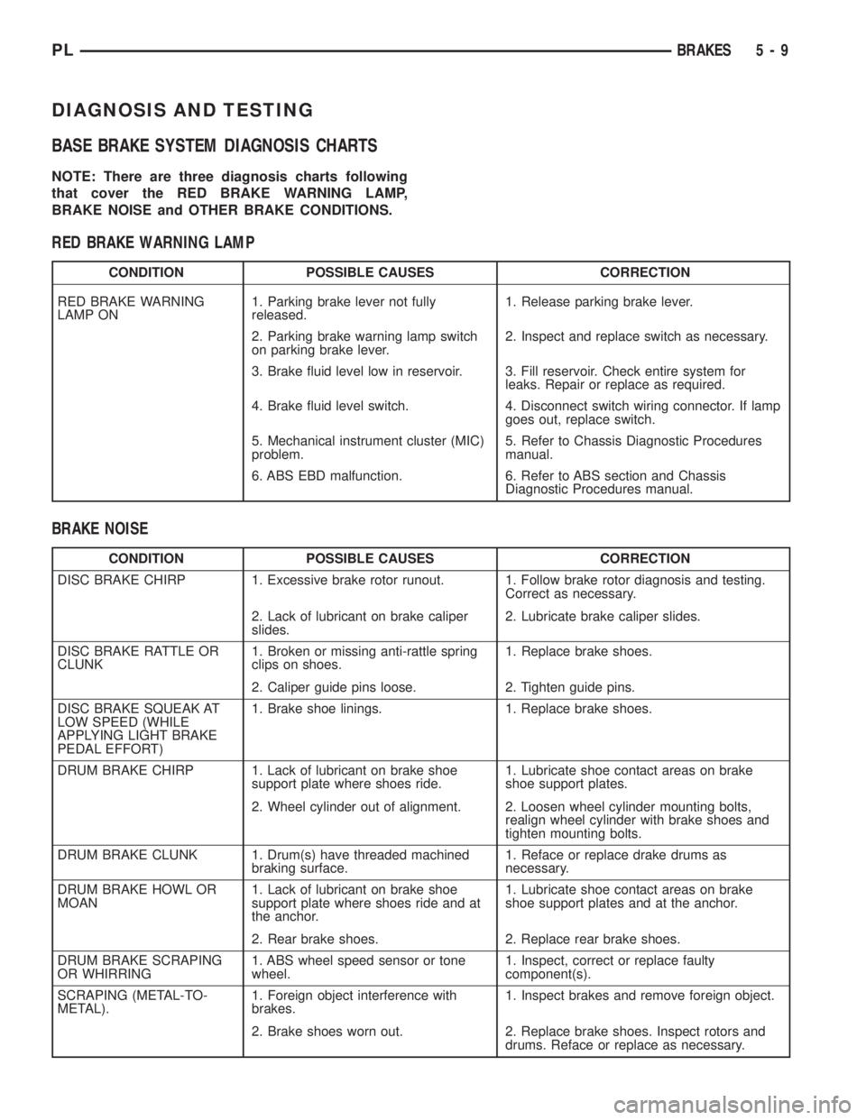
BASE BRAKE SYSTEM DIAGNOSIS CHARTS
NOTE: There are three diagnosis charts following
that cover the RED BRAKE WARNING LAMP,
BRAKE NOISE and OTHER BRAKE CONDITIONS.
RED BRAKE WARNING LAMP
CONDITION POSSIBLE CAUSES CORRECTION
RED BRAKE WARNING
LAMP ON1. Parking brake lever not fully
released.1. Release parking brake lever.
2. Parking brake warning lamp switch
on parking brake lever.2. Inspect and replace switch as necessary.
3. Brake fluid level low in reservoir. 3. Fill reservoir. Check entire system for
leaks. Repair or replace as required.
4. Brake fluid level switch. 4. Disconnect switch wiring connector. If lamp
goes out, replace switch.
5. Mechanical instrument cluster (MIC)
problem.5. Refer to Chassis Diagnostic Procedures
manual.
6. ABS EBD malfunction. 6. Refer to ABS section and Chassis
Diagnostic Procedures manual.
BRAKE NOISE
CONDITION POSSIBLE CAUSES CORRECTION
DISC BRAKE CHIRP 1. Excessive brake rotor runout. 1. Follow brake rotor diagnosis and testing.
Correct as necessary.
2. Lack of lubricant on brake caliper
slides.2. Lubricate brake caliper slides.
DISC BRAKE RATTLE OR
CLUNK1. Broken or missing anti-rattle spring
clips on shoes.1. Replace brake shoes.
2. Caliper guide pins loose. 2. Tighten guide pins.
DISC BRAKE SQUEAK AT
LOW SPEED (WHILE
APPLYING LIGHT BRAKE
PEDAL EFFORT)1. Brake shoe linings. 1. Replace brake shoes.
DRUM BRAKE CHIRP 1. Lack of lubricant on brake shoe
support plate where shoes ride.1. Lubricate shoe contact areas on brake
shoe support plates.
2. Wheel cylinder out of alignment. 2. Loosen wheel cylinder mounting bolts,
realign wheel cylinder with brake shoes and
tighten mounting bolts.
DRUM BRAKE CLUNK 1. Drum(s) have threaded machined
braking surface.1. Reface or replace drake drums as
necessary.
DRUM BRAKE HOWL OR
MOAN1. Lack of lubricant on brake shoe
support plate where shoes ride and at
the anchor.1. Lubricate shoe contact areas on brake
shoe support plates and at the anchor.
2. Rear brake shoes. 2. Replace rear brake shoes.
DRUM BRAKE SCRAPING
OR WHIRRING1. ABS wheel speed sensor or tone
wheel.1. Inspect, correct or replace faulty
component(s).
SCRAPING (METAL-TO-
METAL).1. Foreign object interference with
brakes.1. Inspect brakes and remove foreign object.
2. Brake shoes worn out. 2. Replace brake shoes. Inspect rotors and
drums. Reface or replace as necessary.
PLBRAKES 5 - 9
Page 148 of 1285
AMBER ABS WARNING LAMP
The amber ABS warning lamp is located in the
instrument cluster. The purpose of the warning lamp
is discussed in detail below.
When the ignition key is turned to the ON posi-
tion, the amber ABS warning lamp is lit until the
CAB completes its self-tests and turns off the lamp
(approximately 4 seconds). The amber ABS warning
lamp will illuminate when the CAB detects a condi-
tion that results in the shutdown of ABS function.
The CAB sends a message to the mechanical instu-
ment cluster (MIC) instructing it to turn on the
amber ABS warning lamp.
Under most conditions, when the amber ABS warn-
ing lamp is on, only the ABS function of the brake
system is affected; The electronic brake distribution
(EBD), the base brake system and the ability to stop
the vehicle are not affected.
WHEEL SPEED SENSOR (WSS)
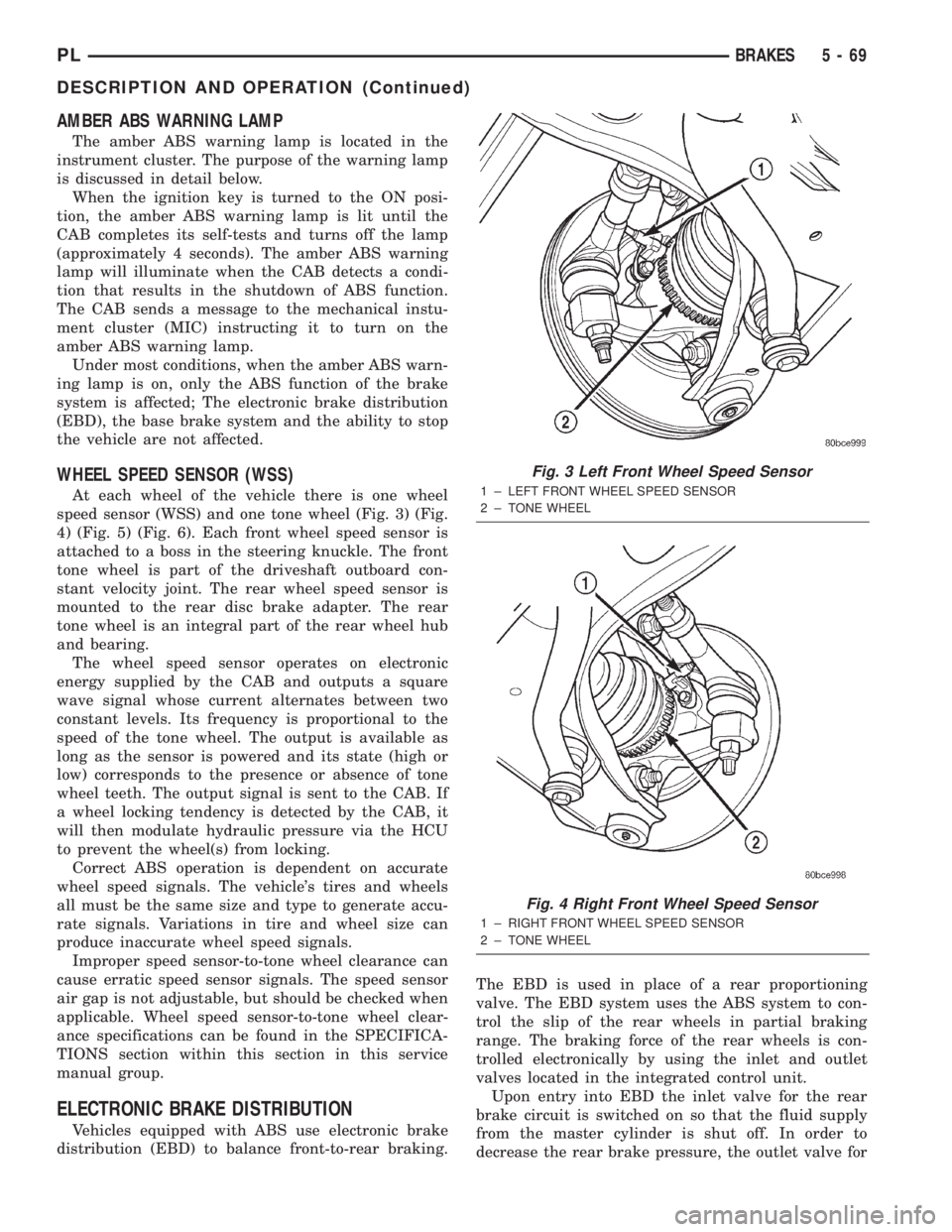
At each wheel of the vehicle there is one wheel
speed sensor (WSS) and one tone wheel (Fig. 3) (Fig.
4) (Fig. 5) (Fig. 6). Each front wheel speed sensor is
attached to a boss in the steering knuckle. The front
tone wheel is part of the driveshaft outboard con-
stant velocity joint. The rear wheel speed sensor is
mounted to the rear disc brake adapter. The rear
tone wheel is an integral part of the rear wheel hub
and bearing.
The wheel speed sensor operates on electronic
energy supplied by the CAB and outputs a square
wave signal whose current alternates between two
constant levels. Its frequency is proportional to the
speed of the tone wheel. The output is available as
long as the sensor is powered and its state (high or
low) corresponds to the presence or absence of tone
wheel teeth. The output signal is sent to the CAB. If
a wheel locking tendency is detected by the CAB, it
will then modulate hydraulic pressure via the HCU
to prevent the wheel(s) from locking.
Correct ABS operation is dependent on accurate
wheel speed signals. The vehicle's tires and wheels
all must be the same size and type to generate accu-
rate signals. Variations in tire and wheel size can
produce inaccurate wheel speed signals.
Improper speed sensor-to-tone wheel clearance can
cause erratic speed sensor signals. The speed sensor
air gap is not adjustable, but should be checked when
applicable. Wheel speed sensor-to-tone wheel clear-
ance specifications can be found in the SPECIFICA-
TIONS section within this section in this service
manual group.
ELECTRONIC BRAKE DISTRIBUTION
Vehicles equipped with ABS use electronic brake
distribution (EBD) to balance front-to-rear braking.The EBD is used in place of a rear proportioning
valve. The EBD system uses the ABS system to con-
trol the slip of the rear wheels in partial braking
range. The braking force of the rear wheels is con-
trolled electronically by using the inlet and outlet
valves located in the integrated control unit.
Upon entry into EBD the inlet valve for the rear
brake circuit is switched on so that the fluid supply
from the master cylinder is shut off. In order to
decrease the rear brake pressure, the outlet valve for
Fig. 3 Left Front Wheel Speed Sensor
1 ± LEFT FRONT WHEEL SPEED SENSOR
2 ± TONE WHEEL
Fig. 4 Right Front Wheel Speed Sensor
1 ± RIGHT FRONT WHEEL SPEED SENSOR
2 ± TONE WHEEL
PLBRAKES 5 - 69
DESCRIPTION AND OPERATION (Continued)
Page 248 of 1285
INSTRUMENT PANEL SYSTEMS
TABLE OF CONTENTS
page page
GENERAL INFORMATION
INTRODUCTION..........................1
DESCRIPTION AND OPERATION
HEADLAMP SWITCH......................2
INSTRUMENT CLUSTER....................2
WARNING AND INDICATOR LAMPS..........2
DIAGNOSIS AND TESTING
AIRBAG WARNING SYSTEM................2
BRAKE SYSTEM WARNING LAMP TEST.......2
INSTRUMENT CLUSTER LAMPS.............2
LOW OIL PRESSURE WARNING LAMP TEST...3
MULTIPLE/INDIVIDUAL GAUGES
INOPERATIVE..........................4
SERVICE PROCEDURES
INSTRUMENT CLUSTER SELF-DIAGNOSTICS...4
REMOVAL AND INSTALLATION
ACCESSORY SWITCH/POWER OUTLET
BEZEL................................4CENTER CONSOLE FLOOD LAMP............5
CIGAR LIGHTER / POWER OUTLET
ASSEMBLY.............................5
GLOVE BOX DOOR/BIN....................6
GLOVE BOX DOOR/BIN....................6
GLOVE BOX SWITCH/LAMP.................6
INSTRUMENT CLUSTER....................6
INSTRUMENT CLUSTER BEZEL..............6
INSTRUMENT CLUSTER LAMPS.............7
INSTRUMENT PANEL ASSEMBLY............7
INSTRUMENT PANEL CENTER BEZEL........10
INSTRUMENT PANEL END CAPS............10
INSTRUMENT PANEL TOP COVER...........10
LOWER INSTRUMENT PANEL COVER........10
LOWER STORAGE BIN....................10
STEERING COLUMN SHROUDS.............11
GENERAL INFORMATION
INTRODUCTION
The purpose of the dash gauges and indicator
lamps is to keep the driver informed about the oper-
ating condition of the vehicle. If an abnormal condi-
tion occurs, the driver is informed by indicator lamp.
The driver can seek service before damage occurs.
Indicator lamps use ON/OFF switch functions for
operation, while gauges use a sending unit or sensor.
The Instrument Panel can be removed as an
assembly after a few part are removed to allow
access to the retaining bolts. There is one self-align-
ing bulkhead connector on the left underside of the
instrument panel replacing most of the main harness
connectors. Once removed, the instrument panel can
be serviced for replacement. Most of the parts of the
instrument panel can be replaced individually with-
out removing the complete instrument panel assem-
bly.
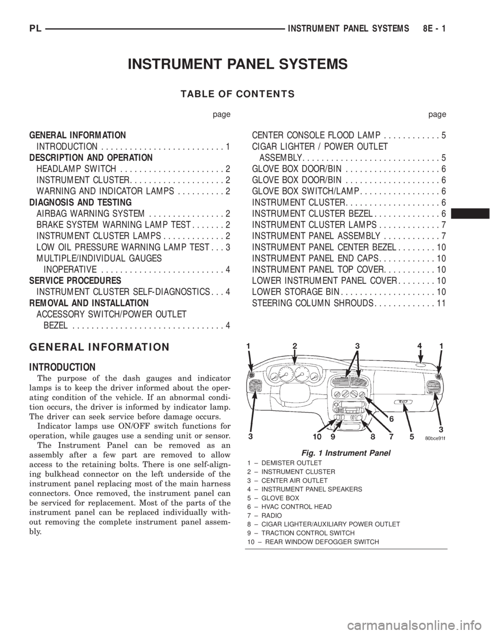
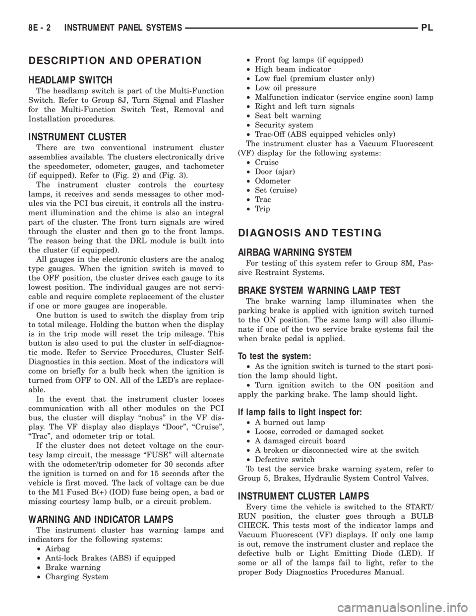
Fig. 1 Instrument Panel
1 ± DEMISTER OUTLET
2 ± INSTRUMENT CLUSTER
3 ± CENTER AIR OUTLET
4 ± INSTRUMENT PANEL SPEAKERS
5 ± GLOVE BOX
6 ± HVAC CONTROL HEAD
7 ± RADIO
8 ± CIGAR LIGHTER/AUXILIARY POWER OUTLET
9 ± TRACTION CONTROL SWITCH
10 ± REAR WINDOW DEFOGGER SWITCH
PLINSTRUMENT PANEL SYSTEMS 8E - 1
Page 249 of 1285
DESCRIPTION AND OPERATION
HEADLAMP SWITCH
The headlamp switch is part of the Multi-Function
Switch. Refer to Group 8J, Turn Signal and Flasher
for the Multi-Function Switch Test, Removal and
Installation procedures.
INSTRUMENT CLUSTER
There are two conventional instrument cluster
assemblies available. The clusters electronically drive
the speedometer, odometer, gauges, and tachometer
(if equipped). Refer to (Fig. 2) and (Fig. 3).
The instrument cluster controls the courtesy
lamps, it receives and sends messages to other mod-
ules via the PCI bus circuit, it controls all the instru-
ment illumination and the chime is also an integral
part of the cluster. The front turn signals are wired
through the cluster and then go to the front lamps.
The reason being that the DRL module is built into
the cluster (if equipped).
All gauges in the electronic clusters are the analog
type gauges. When the ignition switch is moved to
the OFF position, the cluster drives each gauge to its
lowest position. The individual gauges are not servi-
cable and require complete replacement of the cluster
if one or more gauges are inoperable.
One button is used to switch the display from trip
to total mileage. Holding the button when the display
is in the trip mode will reset the trip mileage. This
button is also used to put the cluster in self-diagnos-
tic mode. Refer to Service Procedures, Cluster Self-
Diagnostics in this section. Most of the indicators will
come on briefly for a bulb heck when the ignition is
turned from OFF to ON. All of the LED's are replace-
able.
In the event that the instrument cluster looses
communication with all other modules on the PCI
bus, the cluster will display ªnobusº in the VF dis-
play. The VF display also displays ªDoorº, ªCruiseº,
ªTracº, and odometer trip or total.
If the cluster does not detect voltage on the cour-
tesy lamp circuit, the message ªFUSEº will alternate
with the odometer/trip odometer for 30 seconds after
the ignition is turned on and for 15 seconds after the
vehicle is first moved. The lack of voltage can be due
to the M1 Fused B(+) (IOD) fuse being open, a bad or
missing courtesy lamp bulb, or a circuit problem.
WARNING AND INDICATOR LAMPS
The instrument cluster has warning lamps and
indicators for the following systems:
²Airbag
²Anti-lock Brakes (ABS) if equipped
²Brake warning
²Charging System²Front fog lamps (if equipped)
²High beam indicator
²Low fuel (premium cluster only)
²Low oil pressure
²Malfunction indicator (service engine soon) lamp
²Right and left turn signals
²Seat belt warning
²Security system
²Trac-Off (ABS equipped vehicles only)
The instrument cluster has a Vacuum Fluorescent
(VF) display for the following systems:
²Cruise
²Door (ajar)
²Odometer
²Set (cruise)
²Trac
²Trip
DIAGNOSIS AND TESTING
AIRBAG WARNING SYSTEM
For testing of this system refer to Group 8M, Pas-
sive Restraint Systems.
BRAKE SYSTEM WARNING LAMP TEST
The brake warning lamp illuminates when the
parking brake is applied with ignition switch turned
to the ON position. The same lamp will also illumi-
nate if one of the two service brake systems fail the
when brake pedal is applied.
To test the system:
²As the ignition switch is turned to the start posi-
tion the lamp should light.
²Turn ignition switch to the ON position and
apply the parking brake. The lamp should light.
If lamp fails to light inspect for:
²A burned out lamp
²Loose, corroded or damaged socket
²A damaged circuit board
²A broken or disconnected wire at the switch
²Defective switch
To test the service brake warning system, refer to
Group 5, Brakes, Hydraulic System Control Valves.
INSTRUMENT CLUSTER LAMPS
Every time the vehicle is switched to the START/
RUN position, the cluster goes through a BULB
CHECK. This tests most of the indicator lamps and
Vacuum Fluorescent (VF) displays. If only one lamp
is out, remove the instrument cluster and replace the
defective bulb or Light Emitting Diode (LED). If
some or all of the lamps fail to light, refer to the
proper Body Diagnostics Procedures Manual.
8E - 2 INSTRUMENT PANEL SYSTEMSPL
Page 250 of 1285
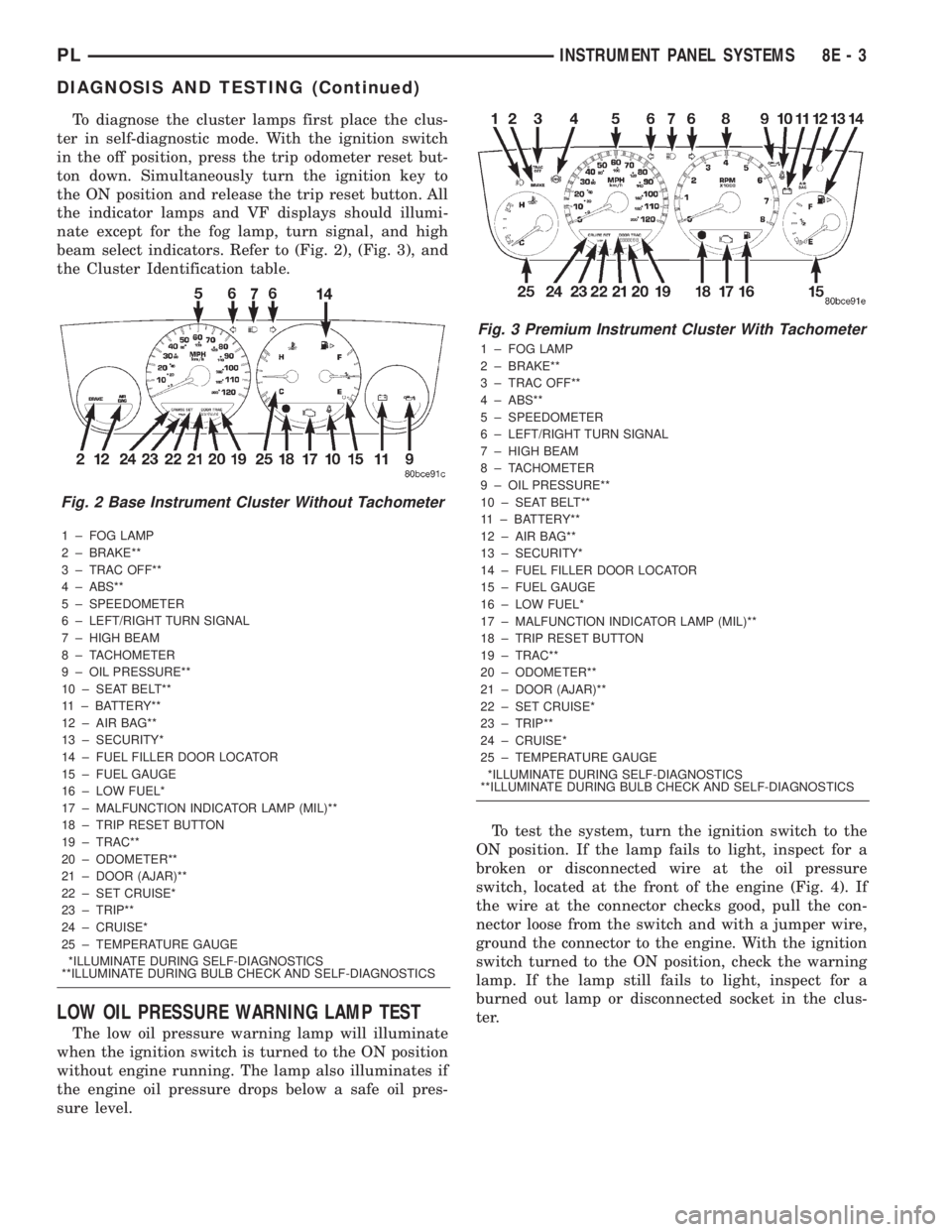
To diagnose the cluster lamps first place the clus-
ter in self-diagnostic mode. With the ignition switch
in the off position, press the trip odometer reset but-
ton down. Simultaneously turn the ignition key to
the ON position and release the trip reset button. All
the indicator lamps and VF displays should illumi-
nate except for the fog lamp, turn signal, and high
beam select indicators. Refer to (Fig. 2), (Fig. 3), and
the Cluster Identification table.
1 ± FOG LAMP
2 ± BRAKE**
3 ± TRAC OFF**
4 ± ABS**
5 ± SPEEDOMETER
6 ± LEFT/RIGHT TURN SIGNAL
7 ± HIGH BEAM
8 ± TACHOMETER
9 ± OIL PRESSURE**
10 ± SEAT BELT**
11 ± BATTERY**
12 ± AIR BAG**
13 ± SECURITY*
14 ± FUEL FILLER DOOR LOCATOR
15 ± FUEL GAUGE
16 ± LOW FUEL*
17 ± MALFUNCTION INDICATOR LAMP (MIL)**
18 ± TRIP RESET BUTTON
19 ± TRAC**
20 ± ODOMETER**
21 ± DOOR (AJAR)**
22 ± SET CRUISE*
23 ± TRIP**
24 ± CRUISE*
25 ± TEMPERATURE GAUGE
*ILLUMINATE DURING SELF-DIAGNOSTICS
**ILLUMINATE DURING BULB CHECK AND SELF-DIAGNOSTICS
LOW OIL PRESSURE WARNING LAMP TEST
The low oil pressure warning lamp will illuminate
when the ignition switch is turned to the ON position
without engine running. The lamp also illuminates if
the engine oil pressure drops below a safe oil pres-
sure level.To test the system, turn the ignition switch to the
ON position. If the lamp fails to light, inspect for a
broken or disconnected wire at the oil pressure
switch, located at the front of the engine (Fig. 4). If
the wire at the connector checks good, pull the con-
nector loose from the switch and with a jumper wire,
ground the connector to the engine. With the ignition
switch turned to the ON position, check the warning
lamp. If the lamp still fails to light, inspect for a
burned out lamp or disconnected socket in the clus-
ter.
Fig. 2 Base Instrument Cluster Without Tachometer
Fig. 3 Premium Instrument Cluster With Tachometer
1 ± FOG LAMP
2 ± BRAKE**
3 ± TRAC OFF**
4 ± ABS**
5 ± SPEEDOMETER
6 ± LEFT/RIGHT TURN SIGNAL
7 ± HIGH BEAM
8 ± TACHOMETER
9 ± OIL PRESSURE**
10 ± SEAT BELT**
11 ± BATTERY**
12 ± AIR BAG**
13 ± SECURITY*
14 ± FUEL FILLER DOOR LOCATOR
15 ± FUEL GAUGE
16 ± LOW FUEL*
17 ± MALFUNCTION INDICATOR LAMP (MIL)**
18 ± TRIP RESET BUTTON
19 ± TRAC**
20 ± ODOMETER**
21 ± DOOR (AJAR)**
22 ± SET CRUISE*
23 ± TRIP**
24 ± CRUISE*
25 ± TEMPERATURE GAUGE
*ILLUMINATE DURING SELF-DIAGNOSTICS
**ILLUMINATE DURING BULB CHECK AND SELF-DIAGNOSTICS
PLINSTRUMENT PANEL SYSTEMS 8E - 3
DIAGNOSIS AND TESTING (Continued)
Page 251 of 1285
MULTIPLE/INDIVIDUAL GAUGES INOPERATIVE
Test speedometer, tachometer and other gauges for
malfunction:
(1) Remove the cluster. Refer to Cluster Removal
and Installation.
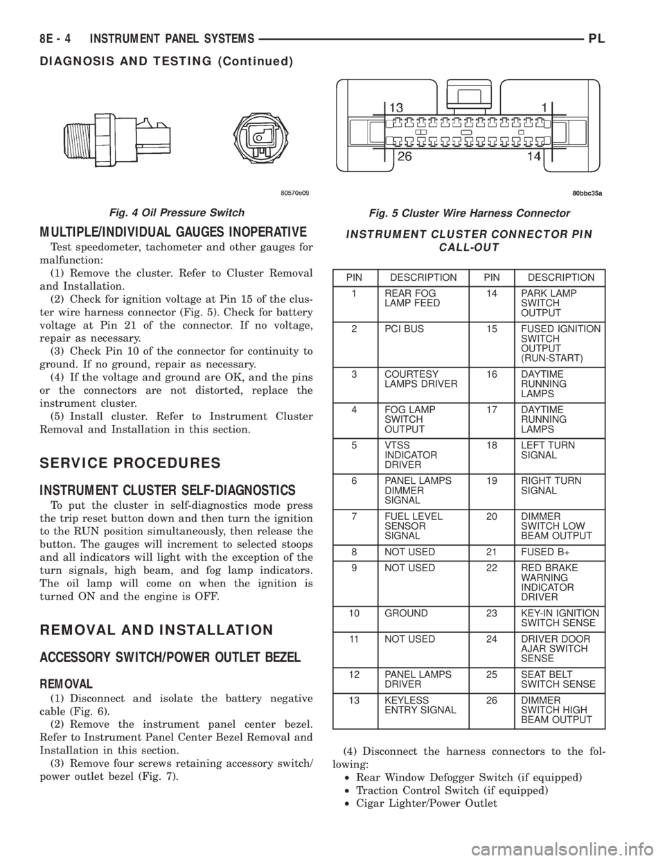
(2) Check for ignition voltage at Pin 15 of the clus-
ter wire harness connector (Fig. 5). Check for battery
voltage at Pin 21 of the connector. If no voltage,
repair as necessary.
(3) Check Pin 10 of the connector for continuity to
ground. If no ground, repair as necessary.
(4) If the voltage and ground are OK, and the pins
or the connectors are not distorted, replace the
instrument cluster.
(5) Install cluster. Refer to Instrument Cluster
Removal and Installation in this section.
SERVICE PROCEDURES
INSTRUMENT CLUSTER SELF-DIAGNOSTICS
To put the cluster in self-diagnostics mode press
the trip reset button down and then turn the ignition
to the RUN position simultaneously, then release the
button. The gauges will increment to selected stoops
and all indicators will light with the exception of the
turn signals, high beam, and fog lamp indicators.
The oil lamp will come on when the ignition is
turned ON and the engine is OFF.
REMOVAL AND INSTALLATION
ACCESSORY SWITCH/POWER OUTLET BEZEL
REMOVAL
(1) Disconnect and isolate the battery negative
cable (Fig. 6).
(2) Remove the instrument panel center bezel.
Refer to Instrument Panel Center Bezel Removal and
Installation in this section.
(3) Remove four screws retaining accessory switch/
power outlet bezel (Fig. 7).(4) Disconnect the harness connectors to the fol-
lowing:
²Rear Window Defogger Switch (if equipped)
²Traction Control Switch (if equipped)
²Cigar Lighter/Power Outlet
Fig. 5 Cluster Wire Harness Connector
INSTRUMENT CLUSTER CONNECTOR PIN
CALL-OUT
PIN DESCRIPTION PIN DESCRIPTION
1 REAR FOG
LAMP FEED14 PARK LAMP
SWITCH
OUTPUT
2 PCI BUS 15 FUSED IGNITION
SWITCH
OUTPUT
(RUN-START)
3 COURTESY
LAMPS DRIVER16 DAYTIME
RUNNING
LAMPS
4 FOG LAMP
SWITCH
OUTPUT17 DAYTIME
RUNNING
LAMPS
5 VTSS
INDICATOR
DRIVER18 LEFT TURN
SIGNAL
6 PANEL LAMPS
DIMMER
SIGNAL19 RIGHT TURN
SIGNAL
7 FUEL LEVEL
SENSOR
SIGNAL20 DIMMER
SWITCH LOW
BEAM OUTPUT
8 NOT USED 21 FUSED B+
9 NOT USED 22 RED BRAKE
WARNING
INDICATOR
DRIVER
10 GROUND 23 KEY-IN IGNITION
SWITCH SENSE
11 NOT USED 24 DRIVER DOOR
AJAR SWITCH
SENSE
12 PANEL LAMPS
DRIVER25 SEAT BELT
SWITCH SENSE
13 KEYLESS
ENTRY SIGNAL26 DIMMER
SWITCH HIGH
BEAM OUTPUT
Fig. 4 Oil Pressure Switch
8E - 4 INSTRUMENT PANEL SYSTEMSPL
DIAGNOSIS AND TESTING (Continued)
Page 253 of 1285
(6) Set base aside and remove base mount ring.
INSTALLATION
(1) Position mount ring to the instrument panel
and feed the wires through ring. Index the cap and
the mount ring with the index tab at 9 o'clock to the
key in the instrument panel. Install the ring.
(2) Connect wires to base. Orient base alignment
rib at 11 o'clock to mate the groove in mount ring at
the same location
(3) Push base into the bezel till it locks.
(4) Install cigar lighter cap and check operation of
element.
GLOVE BOX DOOR/BIN
REMOVAL
(1) Open front passenger door.
(2) Remove three glove box door hinge screws.
(3) Open glove box and remove assembly from
vehicle.
(4) Remove eight screws retaining glove box door
to bin assembly.
(5) Separate glove box door from bin and remove.
INSTALLATION
For installation, reverse the above procedures.
GLOVE BOX DOOR/BIN
REMOVAL
(1) Open front passenger door.
(2) Remove three glove box door hinge screws.
(3) Open glove box and remove assembly from
vehicle.
(4) Remove eight screws retaining glove box door
to bin assembly.(5) Separate glove box door from bin and remove.
INSTALLATION
For installation, reverse the above procedures.
GLOVE BOX SWITCH/LAMP
REMOVAL
(1) Disconnect and isolate the battery negative
cable (Fig. 6).
(2) Open the glove box and push the glove box
sides inward allowing the door bumpers to clear and
the box to tip forward.
(3) Reach inside the opening and squeeze the
lamp/switch retainers until they are disengage.
(4) Pull the switch/lamp rearward and remove it.
Replace the lamp. To replace the switch disconnect
wire and replace the switch.
INSTALLATION
For installation, reverse the above procedures.
INSTRUMENT CLUSTER
CAUTION: The Instrument Cluster MUST be stored
in a face up position or damage will occur to the
gauge operation.
REMOVAL
(1) Disconnect and isolate the battery negative
cable (Fig. 6).
(2) Remove both left and right A-Pillar trim covers.
(3) Remove the instrument panel top cover.
(4) Remove cluster bezel.
(5) Remove the four screws attaching cluster hous-
ing to the base panel.
(6) Pull the cluster rearward to disconnect from
base panel.
(7) Remove the cluster assembly.
INSTALLATION
For installation, reverse the above procedures.
INSTRUMENT CLUSTER BEZEL
REMOVAL
(1) Remove instrument panel top cover. Refer to
Instrument Panel Top Cover Removal and Installa-
tion in this section.
(2) Using a trim stick (special tool #C-4755), gently
pry up on the cluster bezel and remove from vehicle.
INSTALLATION
For installation, reverse the above procedures.
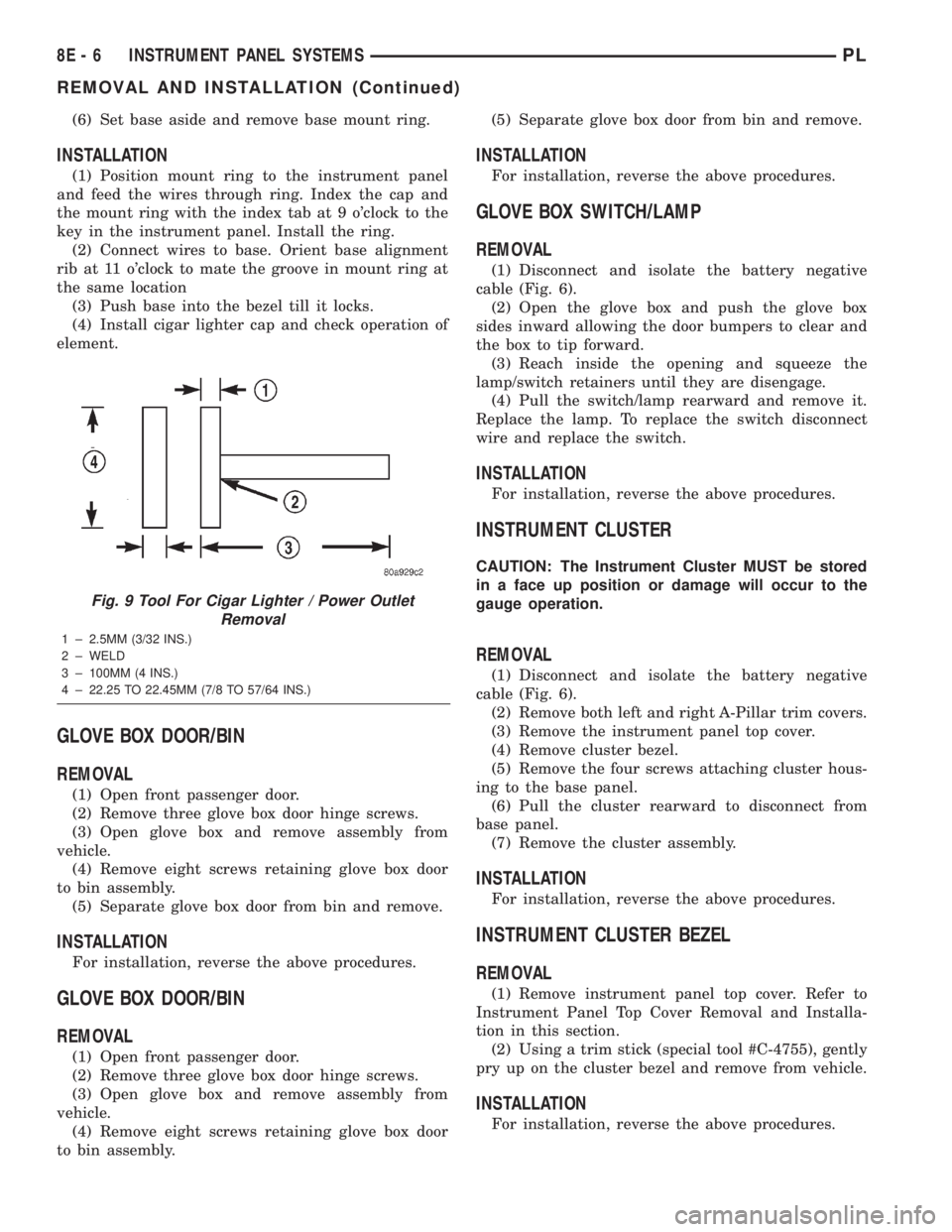
Fig. 9 Tool For Cigar Lighter / Power Outlet
Removal
1 ± 2.5MM (3/32 INS.)
2 ± WELD
3 ± 100MM (4 INS.)
4 ± 22.25 TO 22.45MM (7/8 TO 57/64 INS.)
8E - 6 INSTRUMENT PANEL SYSTEMSPL
REMOVAL AND INSTALLATION (Continued)